
Related Manuals for Waters 2545 Binary Gradient Module


Summary of Contents for Waters 2545 Binary Gradient Module
- Page 1 Waters 2545 Binary Gradient Module Operator’s Guide 71500134902 / Revision A Copyright © Waters Corporation 2006 All rights reserved...
- Page 2 Corporation assumes no responsibility for any errors that may appear in this document. This document is believed to be complete and accurate at the time of publication. In no event shall Waters Corporation be liable for incidental or consequential damages in connection with, or arising from, its use.
-
Page 3: Safety Considerations
Safety considerations Some reagents and samples used with Waters instruments can pose chemical, biological, or radiological hazards. Be sure you are aware of the potentially hazardous effects of all substances you work with. Always follow Good Laboratory Practice, and consult your organization’s safety representative for guidance. -
Page 4: Operating This Device
Intended use ® Waters designed the 2545 Binary Gradient Module to manage solvents under MassLynx™ software control in Waters AutoPurification Systems. Warning: Although some of the modules in the AutoPurification System might carry IVDD labels, the system as a whole is not intended for clinical use. -
Page 5: Table Of Contents
Table of Contents Safety considerations ..................iii Operating this device ..................iv 1 Setting up the 2545 Binary Gradient Module ........1-1 Features ......................1-2 Installing the binary gradient module ............1-4 Unpacking and inspecting ................1-6 Making power connections ................1-7 Making plumbing connections .............. - Page 6 Troubleshooting hardware ................4-8 A Safety Advisories .................. A-1 Warning symbols ....................A-2 Caution symbol ....................A-6 Warnings that apply to all Waters instruments ......... A-7 Electrical and handling symbols ..............A-14 B Specifications ..................B-1 Physical specifications ................... B-2 Environmental specifications ...............
-
Page 7: Setting Up The 2545 Binary Gradient Module
Setting up the 2545 Binary Gradient Module Contents: Topic Page Features Installing the binary gradient module Unpacking and inspecting Making power connections Making plumbing connections Making signal connections 1-16... -
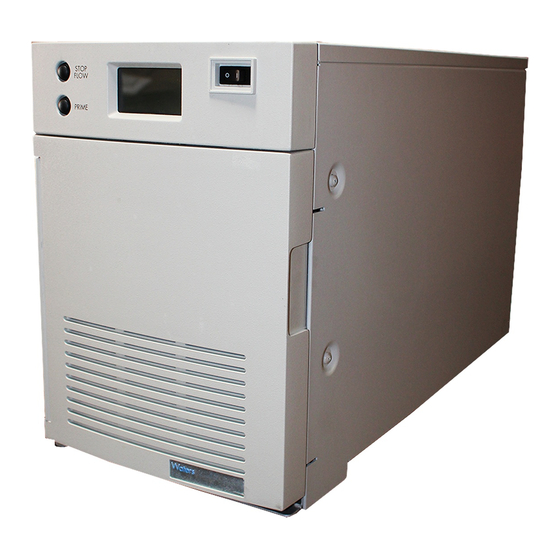
Page 8: Features
Features ® The Waters 2545 Binary Gradient Module is a high-flow, high-pressure mixing binary-gradient pump that delivers solvent for the Waters AutoPurification™ System. Based on Waters high-performance solvent management technology, the binary gradient module provides consistently smooth, pulse-free solvent flow for both analytical and preparative flow rates. - Page 9 Spilled solvent is routed to the drain tube below the front panel. The optional leak sensor should be installed on the leak sensor bracket in the drip tray. See also: Waters AutoPurification System Guide and Waters System Fluidics Organizer Operator’s Guide. Features...
-
Page 10: Installing The Binary Gradient Module
11 inches (28 cm) Depth 31 inches (79 cm) with cables connected at the rear; includes heads and tubes at the front Weight 125 pounds (57 kg) Line voltage 100 to 240 Vac ±10 V Setting up the 2545 Binary Gradient Module... - Page 11 Warning: performance standards. All systems must adhere to a model in which any one “base” Waters module (i.e., the System Fluidics Organizer, the 2545 Binary Gradient Module, or the 3100 Mass Detector) supports no more than two vertically oriented “accessory” Waters modules (e.g., 515 pumps, photodiode array detectors, evaporative light scattering detectors, or dual wavelength absorbance detectors).
-
Page 12: Unpacking And Inspecting
Certificate of Validation. If you detect any damage to the contents of the carton, refer to Shipments, Damages, Claims, and Returns, in Waters Licenses, Warranties, and Support Services. Measure the voltage at the receptacle, and verify that the voltage is between 90 and 264 Vac. -
Page 13: Making Power Connections
Making power connections Do not power on the binary gradient module until you Caution: have completed all plumbing and signal connections. Requirements: Make sure the AC power supply is grounded and has no abrupt voltage fluctuations. The binary gradient module automatically adjusts for AC input voltages of 100 to 240 V, 50/60 Hz. - Page 14 Rear panel of 2545 Binary Gradient Module Number Name Power entry module Fuse holder Ethernet RJ45 port Connector A Connector B Insert the other end of the power cord into a grounded power receptacle. Setting up the 2545 Binary Gradient Module...
-
Page 15: Making Plumbing Connections
Making plumbing connections Check all fittings and tighten if necessary. The fittings Caution: can loosen during shipment, particularly if the module has undergone temperature extremes. Installing solvent inlet tubes Required materials • Solvent inlet tubes assembly (part number 430000573) • 1/2-inch wrench Perform a dry prime before making the initial plumbing Recommendation:... - Page 16 Plumbing connections for seal wash Number Name Seal-wash pump A Seal-wash A inlet tube 1-10 Setting up the 2545 Binary Gradient Module...
- Page 17 Key (Continued) Number Name Filter Seal-wash B outlet tube Drip tray Drain tube Inlet manifold B Seal-wash B connection tube Seal-wash B inlet tube Vent valve Seal-wash pump B Waste outlet at tee fitting Seal-wash A outlet tube Seal-wash A connection tube Inlet manifold A If you plan to run only two solvents, make sure to plumb one solvent into each manifold and connect the tube to a port in each manifold.
- Page 18 Insert the seal-wash solvent supply tube into the top port of the pump A seal-wash pump. Ensure the tube is pressed into the pump before tightening the compression screw to set the ferrule. 1-12 Setting up the 2545 Binary Gradient Module...
- Page 19 Installing the seal-wash solvent supply tubes Install a second tube to the pump B seal-wash pump. Installing the seal-wash waste tube Caution: To properly drain the waste fluid, ensure that the waste tube has no crimps or bends. A crimped or bent drain tube may prevent adequate flow to the waste container.
- Page 20 The drip tray is mounted at the bottom of the binary gradient module bezel. The optional leak sensor should be installed on the leak sensor bracket in the drip tray. Waters AutoPurification System Guide. See also: 1-14 Setting up the 2545 Binary Gradient Module...
- Page 21 Required materials • Drip tray (part number 700001514) • Waste tube, 1/4-inch • Leak sensor (optional; with leak detection module) To install the drip tray on the binary gradient module: Clip the drip tray into the bezel. Slide the 1/4-inch ID waste tube over the barbed drain fitting. Place the free end of the drain tube in an appropriate waste container, and ensure that the drain tube has no crimps or bends.
-
Page 22: Making Signal Connections
LEAK DET (-) on the terminal strip. • Connects the other end of the cable to the 2545 binary gradient module LEAK DET (+) and (-) terminals (terminals 6 and 7 on connector B on the rear panel of the binary gradient module). - Page 23 The terms “Connector A” and “Connector B” are generic and do not refer to pumps A and B. I/O signal connectors Connector A (top) Connector B (bottom) 1 Switch 1 (Out) 1 Switch 3 (Out) 2 Switch 1 (Out) 2 Switch 3 (Out) 3 Switch 2 (Out) 3 Switch 4 (Out) 4 Switch 2 (Out)
- Page 24 Each pair of switch terminals can be connected to an external device. You can operate the switches: • manually from the Direct Functions screen. • automatically in a separation method using a timed table (I/O screen). 1-18 Setting up the 2545 Binary Gradient Module...
- Page 25 Event switch positions and functions Position Function Closes the switch. Opens the switch. Toggle Changes the current state of the switch. Pulse Closes/opens the switch for a user-defined period. No Change Leaves the switch in its current state. Making signal connections 1-19...
- Page 26 1-20 Setting up the 2545 Binary Gradient Module...
-
Page 27: Preparing For Operation
Preparing for operation MassLynx software controls the components of the AutoPurification System. This chapter explains how to configure the binary gradient module as a chromatographic (system) pump in the AutoPurification System. Contents: Topic Page Powering on Scanning connected instruments Configuring 515 pumps Creating the inlet method Defining the gradient 2-10... -
Page 28: Powering On
Powering on When you have completed all electrical, plumbing, and signal connections, you are ready to power on the 2545 Binary Gradient Module. Caution: Do not power on the binary gradient module until you have completed all electrical, plumbing, and signal connections. -
Page 29: Scanning Connected Instruments
Scanning connected instruments The pump control module in the system fluidics organizer controls any 515 pumps in the system. Scanning the instruments in the system retrieves serial numbers and ensures communication with MassLynx. See also: System Fluidics Organizer Operator’s Guide. To scan the instruments: From the main menu, click Start >... - Page 30 Viewing the inlet method Click , and then select Configure Waters Pump Control Modules. See also: “Configuring Waters Pump Control Modules” in FractionLynx Help. Preparing for operation...
- Page 31 Waters Pump Control Configuration dialog box Click Scan. If scanning does not complete in a few minutes, ensure that: • The cables are correctly and securely attached. • The on/off switches are set to On. • Communication settings are correctly specified.
-
Page 32: Configuring 515 Pumps
Configuring 515 pumps To configure a system that has one or more 515 pumps: Check Enable for 515 (A), 515 (B), and/or 515 (C). They can function either as contributors to solvent flow A or B, or as non-contributors. Select the GPIB address (for the pump control module) in the “Associate with an instrument”... - Page 33 Defining 515 pump parameters For each 515 pump, enter the initial flow rate, and select the solvent name. The default flow rate is 1.00 mL/min. You can change the low and high pressure limits for each 515 pump. Tip: 10. Click OK. Requirement: For each 515 pump that is not a contributor to the system flow (makeup pump), in the Events table, you must program the flow...
-
Page 34: Creating The Inlet Method
Recommendations: The run time you enter here applies only to the 2545 Binary Gradient Module. You must specify a run time for each module in the AutoPurification System. Run times are typically the same for all modules and are determined from your Standard Operating Procedures (SOP) or method development. - Page 35 In the Solvent Names area, enter names for Solvent A and Solvent B. To change solvent names, enter a name for solvent A in the label A box and enter a name for Solvent B in the label B box. Examples: acetonitrile, methanol, water.
-
Page 36: Defining The Gradient
Defining the gradient The gradient table controls solvent flow and composition during each sample run. The Curve column indicates the gradient curve’s profile. Example: The curve specified in row 2 runs in the interval between gradient event 1’s initial conditions and gradient event 2’s initial conditions. To define the gradient: In the Modify Instrument Method >... - Page 37 In the next row of the Time column, enter the run time at which you want gradient event 2 to start. In the Flow column, enter the solvent flow rate you want the pump to reach by the start of gradient event 3. In the %A or %B column, enter the percent solvent composition you want the pump to reach by the start of gradient event 3.
- Page 38 Entering the total system flow rate 2-12 Preparing for operation...
- Page 39 • To display the flow rate of the BGM alone, click Pump Only. In this example, the system calculates the flow rate of the 2545 BGM as 23.75 mL/min. Calculating the flow rate of the 2545 BGM (Pump Only) 11. When you are finished setting up the method, click OK. Defining the gradient 2-13...
-
Page 40: Entering Timed Events
Entering timed events To enter the timed events: In the Modify Instrument Method screen, click the Events tab. Entering timed events In the Initial Switch States area, set the Switch 1 state. You can set the four event switches to the states you want at the start of each run. Valid switch states State Description... - Page 41 Valid switch states (Continued) State Description Turns on a contact closure that triggers an external or internal event. With this function, the contact closure remains closed until an Off function is sent by the software. Turns off the contact closure for the event. With this function, the contact closure is broken.
-
Page 42: Setting Up Analog Signals
Setting up analog signals You can set up output analog signals to record system information. Requirement: Analog signals require a Waters eSAT/IN Module in the system. See also: Waters e-SAT/IN Module Installation Guide. To enter analog information: In the Modify Instrument Method screen, click the Analog tab. -
Page 43: Preparing Solvent Reservoirs
Preparing solvent reservoirs Tip: When operating at high flow rates, and/or with viscous solvents, you can remove the solvent reservoir filters if you need to reduce flow restriction. Warning: The binary gradient module does not require pressurized solvent containers for reliable operation. If using pressurized containers for blanketing large containers of solvent, do not exceed 5 psig. - Page 44 Opening the Diagnostics Chromatographic Pump dialog box Select Diagnostics > Seal-Wash Prime. The seal-wash pump starts priming. Press the plunger on the syringe to dispense the seal-wash solution. To stop the priming procedure, select Diagnostics > Seal-Wash Prime. Remove the syringe and adapter, and then place the plunger-seal-wash inlet tube into the purge/plunger-seal-wash solvent reservoir.
- Page 45 To perform a dry prime: Fill the syringe with priming solution. Remove the inlet tube and nut from the inlet manifold. Screw the nut from the priming syringe into the port that you want to prime. Inject the solvent into the manifold. Remove the syringe and reinstall the inlet tube.
- Page 46 Selecting the solvents for priming Select the solvents you plan to run. Choose solvent A1 or A2, and then choose solvent B1 or B2. In the Flow Rate (mL/min) field, enter the solvent flow rate for the priming run. In the Time (min) field, enter the number of minutes for priming. Click Prime.
-
Page 47: Maintenance
Maintenance Contents: Topic Page Maintenance considerations Removing the pump head and seal-wash assemblies Replacing the seals and O-ring 3-10 Replacing the plunger 3-16 Replacing an inlet check valve cartridge 3-20 Replacing an outlet check valve cartridge 3-22 Replacing the vent valve rotor-seal assembly 3-24 Diagnostics and configuration 3-28... -
Page 48: Maintenance Considerations
Spare parts Waters recommends that you replace only parts mentioned in this document. For spare parts details, see the Waters Quality Parts Locator on the Waters web site's Services/Support page. Contacting Waters Technical Service If you are in the USA or Canada, contact Waters Technical Service (800 252-4752). - Page 49 Seal life Seal life of three to six months or longer is possible, but is highly dependent on the following: • Mobile phases and modifiers used • Flow rate • Use of seal-wash • Back pressure • Cleanliness of the mobile phases •...
-
Page 50: Removing The Pump Head And Seal-Wash Assemblies
Removing the pump head and seal-wash assemblies Remove the pump head and seal-wash assemblies whenever you need to: • Replace the plunger seals and O-ring • Clean or replace a plunger Piston chamber components Maintenance... - Page 51 Number Name Seal-wash housing Transducer inlet tube assembly Transducer assembly Inlet check valve holder Inlet check valve cartridge Pump head O-ring Plunger seal Plunger wash seal Head support plate Plunger retaining nut Plunger Required materials • Squeeze bottle with methanol •...
- Page 52 Controlling the plunger Select the pump you plan to perform maintenance on (A or B). Select the head you plan to perform maintenance on (left or right). Click Move Plunger Back. The plunger moves back. Disconnect the pressure transducer cable from the front bezel. Disconnecting the cable and inlet check valve Using the 1/2-inch open-end wrench, disconnect the inlet check valve fitting from the pump head.
- Page 53 Disconnecting the transducer outlet tube Disconnect the two seal-wash tubes from the sides of the pump head. 10. While supporting the pump head’s weight, use a T27 TORX driver to remove the four screws in the support plate. Removing the head assembly from the housing Caution: Keep the pump head aligned with the plunger to avoid damaging the plunger.
- Page 54 Caution: When you are placing the head assembly on a flat surface, take care not to damage the cable that protrudes from the transducer face. 13. Use a T27 TORX driver to remove the two screws securing the pump head assembly to the support plate, and then remove the support plate. Removing the pump head assembly Remove the screws that secure the Remove the support plate.
- Page 55 14. Remove the seal-wash housing. Removing the seal-wash housing 15. In the Manual Plunger Control dialog box, click Move Plunger Forward. The plunger moves forward. Removing the pump head and seal-wash assemblies...
-
Page 56: Replacing The Seals And O-Ring
Replacing the seals and O-ring This procedure involves replacing the: • Plunger seal • O-ring • Plunger wash seal Required materials • Plastic tweezers (part number 605000106) • Replacement seal kit (part number 700001494) • Seal insertion/extraction tool (part number 405001667) •... - Page 57 Remove the O-ring using plastic tweezers. Removing the O-ring Wet the seal cavity and new plunger seal with methanol. Wetting the seal cavity and new plunger seal Using the seal insertion/extraction tool, insert the new plunger seal into the pump head. Installing the plunger seal Replacing the seals and O-ring 3-11...
- Page 58 Insert the new O-ring into the O-ring groove in the pump head. Installing the O-ring Remove the seal-wash assembly as described on page 3-4. Remove the existing plunger wash seal using plastic tweezers. Removing the existing plunger wash seal Wet the new plunger wash seal with methanol and insert it into the seal-wash housing.
- Page 59 10. Insert the seal-wash assembly into the pump assembly and align the screw hole in both assemblies. 11. Reassemble the pump head, seal-wash assembly, and support plates and secure them with screws using the T27 TORX driver. Ensure that the drain fitting and check valve housing line up.
- Page 60 Wetting the seal cavity Wetting the plunger Caution: To prevent damaging the plunger, ensure the plunger is retracted before performing the next step. 16. Carefully align the pump head with the plunger and gently push the pump head onto the plunger, until the four screw holes align with the holes in the support plate.
- Page 61 Connecting seal-wash tubes Number Name Seal-wash A connection tube Seal-wash A inlet tube Seal-wash B outlet tube Seal-wash B connection tube Seal-wash B inlet tube Seal-wash A outlet tube 19. If the binary gradient module does not have solvent in the tubes, perform a wet prime to draw solvent into the plunger cavity.
-
Page 62: Replacing The Plunger
Replacing the plunger Required materials • Grease pack • Plunger assembly, 0.280-inch diameter (part number 700001532) • Squeeze bottle with methanol • 5/8-inch open-end wrench To replace the plunger: In the MassLynx Main window, select Diagnostics. Select Diagnostics > Manual Plunger Control. In the Pump area, select the pump you plan to perform maintenance on. - Page 63 Using the grease pack supplied with the plunger, apply grease to the ball-end of the new plunger. Greasing the plunger Install the e-clip, flat washer, and three wave washers in that order. Make sure the wave washers are bowed toward the plunger tip. Installing the e-clip and washers Number Name...
- Page 64 Key (Continued) Number Name Wave washers (3) Plunger retaining nut Insert the new plunger into the actuator piston, and tighten the plunger-retaining nut with a 5/8-inch open-end wrench. Be careful not to damage the plunger when sliding the open-end wrench over it. 10.
- Page 65 Reconnect the transducer cable to the appropriate connector on the front panel, making sure it clicks into place. Prime the binary gradient module. Replacing the plunger 3-19...
-
Page 66: Replacing An Inlet Check Valve Cartridge
Replacing an inlet check valve cartridge The binary gradient module has one inlet check valve per pump head. The check valves are made of synthetic ruby and sapphire contained in easy-to-replace cartridges. Required materials • Plastic tweezers (part number 605000106) •... - Page 67 Wetting the new inlet check valve cartridge Insert the replacement cartridge into the holder with the arrow pointed away from the hex nut. Inserting the inlet check valve cartridge Insert the cartridge holder in the head and finger tighten the fitting. Use the 1/2-inch wrench to tighten the check valve holder 1/8 of a turn beyond finger-tight.
-
Page 68: Replacing An Outlet Check Valve Cartridge
Replacing an outlet check valve cartridge The binary gradient module path contains two outlet check valves per pump manifold. The check valves are made of synthetic ruby and sapphire in easy-to-replace cartridges. Required materials • Plastic tweezers (part number 605000106) •... - Page 69 Caution: To avoid damaging the check valve holder, always use plastic tweezers when performing the next step. Use plastic tweezers to remove the existing cartridge from inside the manifold. Removing the existing outlet check valve cartridge Inspect the check valve holder and clean it if necessary. Rinse the components with methanol or an appropriate solvent.
-
Page 70: Replacing The Vent Valve Rotor-Seal Assembly
Replacing the vent valve rotor-seal assembly Required materials • Seal insertion/extraction tool (part number 405001667) • Vent valve rotor-seal (part number 700001483) • 5/8-inch open-end wrench To replace the vent valve rotor-seal assembly: Using the 5/8-inch open-end wrench, loosen the preload assembly at the front of the vent valve, and then remove it. - Page 71 Place the new rotor-seal into the valve, aligning the key with the slot in the actuator. The rotor orientation does not matter, as long as the key aligns with the slot. Replace the preload assembly onto the front of the valve and finger tighten it until it stops turning.
- Page 72 Rear panel of the 2545 Binary Gradient Module Number Name Power entry module Fuse holder Connector B Connector A Ethernet RJ45 port 3-26 Maintenance...
- Page 73 Use a flat-blade screwdriver to remove the fuse holder, which is located below the power entry module. Removing fuses Caution: For continued protection against fire hazard, replace fuses with the appropriate type and rating. Replace both fuses with fuses of the appropriate type, and reinsert them into the holder.
-
Page 74: Diagnostics And Configuration
Diagnostics and configuration The MassLynx software provides a number of diagnostics, including the ability to test the chromatographic pump and the ability to identify which binary gradient module is currently communicating with the diagnostics interface. Diagnostics menu options Menu option Description Manual Control Provides direct control to the pump... -
Page 75: Performing The Leak Test
Performing the leak test The leak test performs a pressure ramp up, and then monitors the pressure decay in the binary gradient module to determine if the inlet check valves, tubes, fittings, or plunger seals are faulty. Perform the leak test whenever you: •... - Page 76 In the Test Pressure text box, enter the pressure limit for which you will test the pump. Click Start Leak Test. The status of the leak test appears in the Test Progress area. When the leak test is finished, the Test Results area displays the results.
- Page 77 Resolving leak problems To resolve leak problems: Inspect all fittings, tubing, and the vent valve rotor. If leaks cannot be resolved by checking fittings and tubing, inspect the check valves and pump seals. If both the right and left heads of either pump A or B fail with about the same decay rate, the leak is likely in the areas that are common to both pump heads, such as: •...
- Page 78 3-32 Maintenance...
-
Page 79: Troubleshooting
Troubleshooting Contents: Topic Page System troubleshooting Alarm reset Error messages Troubleshooting hardware... -
Page 80: System Troubleshooting
System troubleshooting To prevent injury, always observe good laboratory Warning: practices when you handle solvents, change tubes, or operate the binary gradient module. Know the physical and chemical properties of the solvents you use. Refer to the Material Safety Data Sheets for the solvents in use. - Page 81 Many problems with a binary gradient module can be easily corrected. However, if you cannot correct a condition, you can contact Waters Technical Service. If you are in the USA or Canada, contact Waters Technical Service (800 252-4752). If you are not in the USA or Canada, visit http://www.waters.com...
-
Page 82: Alarm Reset
Alarm reset When an error occurs, the binary gradient module displays an alarm message and emits three short beeps. To acknowledge an alarm, press the Stop Flow button. The binary gradient module displays the main screen or the next alarm message, or resets the pump. -
Page 83: Error Messages
(69 bar, 1000 psi) was encountered during homing. Check the outlet tubes, vent valve, and other fluid-handling interfaces that could have a blockage. If this message persists, call Waters Technical Service. Pump Homing Error: The pump head could not travel the full stroke Travel Range Failure distance after it detected the home position. - Page 84 Pump Motor Driver HW The electronics detected an over-current Fault condition on the pump motors. If this message persists, call Waters Technical Service. Pump Motor Lost A requested pump motor movement failed its Synchronization encode feedback check. This is usually caused by pressures exceeding 34,500 kPa (345 bar, 5000 psi) at flow rates over 100 mL/min.
- Page 85 If this message persists, call Waters Technical Service. Vent Valve Fail HW The system/vent valve detected a movement Detected error. If this message persists, call Waters Technical Service. Error messages...
-
Page 86: Troubleshooting Hardware
Troubleshooting hardware This table contains suggestions for resolving hardware problems in the binary gradient module. If the suggested solutions do not solve the problem, call Waters Technical Service. Troubleshooting the hardware : Symptom Possible Cause Corrective Action Display is blank Unit not powered on Power on unit. - Page 87 Startup diagnostics fail Internal problem Power off and on again. If with controller failure persists, call board, solvent Waters Technical Service. management system, or sample management system Unit does not power on Power cord not Check power cord. connected No power at outlet Check line voltage.
- Page 88 4-10 Troubleshooting...
- Page 89 Safety Advisories Waters instruments display hazard symbols designed to alert you to the hidden dangers of operating and maintaining the instruments. Their corresponding user guides also include the hazard symbols, with accompanying text statements describing the hazards and telling you how to avoid them.
-
Page 90: A Safety Advisories
Heed all warnings when you install, repair, and operate Waters instruments. Waters assumes no liability for the failure of those who install, repair, or operate its instruments to comply with any safety precaution. - Page 91 The following warnings can appear in the user manuals of particular instruments and on labels affixed to them or their component parts. Burst warning This warning applies to Waters instruments fitted with nonmetallic tubing. Pressurized nonmetallic, or polymer, tubing can burst. Warning: Observe these precautions when working around such tubing: •...
- Page 92 Also ensure a gas-fail connection is connected to the HPLC system so that the LC solvent flow stops if the nitrogen supply fails. Mass spectrometer shock hazard This warning applies to all Waters mass spectrometers. Warning: To avoid electric shock, do not remove the mass spectrometer’s protective panels.
- Page 93 Biohazard warning This warning applies to Waters instruments that can be used to process material that might contain biohazards: substances that contain biological agents capable of producing harmful effects in humans. Waters’ instruments and software can be used to analyze or...
-
Page 94: Caution Symbol
Caution symbol The caution symbol signifies that an instrument’s use or misuse can damage the instrument or compromise a sample’s integrity. The following symbol and its associated statement are typical of the kind that alert you to the risk of damaging the instrument or sample. -
Page 95: Warnings That Apply To All Waters Instruments
Warnings that apply to all Waters instruments When operating this device, follow standard quality control procedures and the the equipment guidelines in this section. Attention: Changes or modifications to this unit not expressly approved by the party responsible for compliance could void the user’s authority to operate the equipment. - Page 96 Warning: Use caution when working with any polymer tubing under pressure: • Always wear eye protection when near pressurized polymer tubing. • Extinguish all nearby flames. • Do not use tubing that has been severely stressed or kinked. • Do not use nonmetallic tubing with tetrahydrofuran (THF) or concentrated nitric or sulfuric acids.
- Page 97 (THF) o ácidos nítrico o sulfúrico concentrados. • Hay que tener en cuenta que el cloruro de metileno y el sulfóxido de dimetilo dilatan los tubos no metálicos, lo que reduce la presión de ruptura de los tubos. Warnings that apply to all Waters instruments...
- Page 98 A-10 Safety Advisories...
- Page 99 Advertencia: el usuario deberá saber que si el equipo se utiliza de forma distinta a la especificada por el fabricante, las medidas de protección del equipo podrían ser insuficientes. Warnings that apply to all Waters instruments A-11...
- Page 100 Warning: To protect against fire hazard, replace fuses with those of the same type and rating. Attention: Remplacez toujours les fusibles par d’autres du même type et de la même puissance afin d’éviter tout risque d’incendie. Vorsicht: Zum Schutz gegen Feuergefahr die Sicherungen nur mit Sicherungen des gleichen Typs und Nennwertes ersetzen.
- Page 101 Attenzione: per evitare il rischio di scossa elettrica, scollegare il cavo di alimentazione prima di svolgere la manutenzione dello strumento. Precaución: para evitar descargas eléctricas, desenchufe el cable de alimen- tación del instrumento antes de realizar cualquier reparación. Warnings that apply to all Waters instruments A-13...
-
Page 102: Electrical And Handling Symbols
Electrical and handling symbols Electrical symbols These can appear in instrument user manuals and on the instrument’s front or rear panels. Electrical power on Electrical power off Standby Direct current Alternating current Protective conductor terminal Frame, or chassis, terminal Fuse Recycle symbol: Do not dispose in municipal waste. - Page 103 Handling symbols These handling symbols and their associated text can appear on labels affixed to the outer packaging of Waters instrument and component shipments. Keep upright! Keep dry! Fragile! Use no hooks! Electrical and handling symbols A-15...
- Page 104 A-16 Safety Advisories...
- Page 105 Specifications Contents: Topic Page Physical specifications Environmental specifications Electrical specifications Solvent management system specifications...
-
Page 106: Physical Specifications
Physical specifications Physical specifications Item Specification Height 17 inches (43 cm) Depth (without cables connected at rear; 25 inches without drip tray includes heads and tubes at front) (63.5 cm) Width 11 inches (28 cm) Weight 125 pounds (57 kg) Specifications... -
Page 107: Environmental Specifications
Environmental specifications Environmental specifications Item Specification Operating temperature 4 to 40 °C Humidity 20 to 80%, noncondensing Acoustic noise <60 dBA at idle (instrument-generated) Solvent compatibility Solvents consistent with materials of construction. Salts and buffers can reduce seal life, especially at pressures in excess of 20,700 kPa (207 bar, 3000 psi). -
Page 108: Electrical Specifications
Electrical specifications Electrical specifications Item Specification Protection class Class I Overvoltage category Pollution degree Moisture protection Normal (IPXO) Line voltages, Grounded AC nominal Current requirements 6.5 A Line voltage 100 to 240 Vac ±10% Frequency 50/60 Hz Fuse 10 A, 5 × 20 mm, slow-blow, IEC type Power consumption 650 W Time or user-controllable... - Page 109 Electrical specifications (Continued) Item Specification Stop flow (input) TTL signal or contact closure. Input voltage range: ±30 Vdc. Logic high = >3.0 Vdc ±10%. Logic low = <1.9 Vdc ±10%. Minimum pulse width = 100 msec. Screw terminal connector. Start gradient (input) TTL signal or contact closure.
- Page 110 Electrical specifications (Continued) Item Specification Auxiliary input 2 TTL signal or contact closure. Input voltage range: ±30 Vdc. Logic high = >3.0 Vdc ±10%. Logic low = <1.9 Vdc ±10%. Minimum pulse width = 100 msec. Screw terminal connector. Ground terminals Connected to signal ground and used as reference for outputs.
-
Page 111: Solvent Management System Specifications
Solvent management system specifications Solvent management system specifications Item Specification General High pressure mixing, binary gradient. Priming Ability to self-prime from a solvent container on the floor with wet pump heads and dry tubes (no intervention from the operator such as a syringe). - Page 112 Solvent management system specifications (Continued) Item Specification Composition accuracy ±1.0% absolute (full scale) from 5 to 95% from 1.0 to 130 mL/min using water/water or MeOH/MeOH spiked with dye or marker, back pressure approximately 4140 kPa (41 bar, 600 psi). Composition precision Retention time variation less than 0.3% RSD or 0.1 min SD, whichever is greater.
- Page 113 Flow envelope Pressure (psi) 6000 5000 Flow rate (mL/min) Instrument control and communication specifications Item Specification Ethernet Control from external PC. RS-232 Reserved for future use. Solvent management system specifications...
- Page 114 B-10 Specifications...
-
Page 115: Index
Index Numerics dry prime, performing 2-18 2545 Binary Gradient Module. See Binary Gradient Module electrical specifications electrical symbols A-14 entering analog information 2-16 accessories, unpacking event switches 1-18 acoustic noise airflow requirements alarm message flammable solvents alarm, reset flow envelope... - Page 116 intended use 1-iv internal cooling requirement removing O-ring 3-11 plunger seal 3-10 leak detector signals 1-18 pump head leak problems, resolving 3-31 seal-wash assembly leak test, performing 3-29 replacing line voltage requirement fuses 3-25 outlet check valve cartridges 3-22 pump plunger 3-16 maintenance rotor-seal assembly...
- Page 117 3-13 warning symbols switch states 2-14 waste tube switch terminals 1-17 seal-wash 1-13 symbols vent valve 1-14 caution Waters Technical Service, contacting electrical A-14 handling A-15 weight requirement warning width requirement system outlet tube 1-15 system troubleshooting temperature requirement terminals...
- Page 118 Index-4...
Need help?
Do you have a question about the 2545 Binary Gradient Module and is the answer not in the manual?
Questions and answers