Table of Contents
Advertisement
Advertisement
Table of Contents

Related Manuals for Waters Bus SAT/IN


Summary of Contents for Waters Bus SAT/IN
- Page 1 Artisan Technology Group is your source for quality new and certified-used/pre-owned equipment SERVICE CENTER REPAIRS WE BUY USED EQUIPMENT • FAST SHIPPING AND DELIVERY Experienced engineers and technicians on staff Sell your excess, underutilized, and idle used equipment at our full-service, in-house repair center We also offer credit for buy-backs and trade-ins •...
- Page 2 Waters Bus SAT/IN Module Installation Guide 34 Maple Street Milford, MA 01757 200409TP, Revision 2 Artisan Technology Group - Quality Instrumentation ... Guaranteed | (888) 88-SOURCE | www.artisantg.com...
- Page 3 This manual is believed to be complete and accurate at the time of publication. In no event shall Waters Corporation be liable for incidental or consequential damages in connection with or arising from the use of this manual.
- Page 4 Attention: The Bus SAT/IN Module may be used for IN VITRO diagnostic applications. STOP This is a highly sensitive instrument. Read this installation manual before use. When using the instrument, follow generally accepted procedures for quality control and methods development.
- Page 5 Le présent appareil numérique n’émet pas de bruits radioélectriques dépassant les limites applicables aux appareils numériques de la classe A prescrites dans les règlements sur le brouillage radioélectrique édictés par le Ministère des Communications du Canada. Symbols Used on the Bus SAT/IN Module Alternating current Protective conductor terminal...
- Page 6 Record the following numbers when installing the Waters Bus SAT/IN module Bus SAT/IN module serial number (from label on rear panel) Detector connected to Channel 1 Detector connected to Channel 2 Device on Event 1 and 2 Device on Event 3 and 4...
-
Page 7: Table Of Contents
2.4 Connecting Event Cables............20 2.5 Connecting BCD Cable (Optional) ........24 2.6 Connecting the Power Supply..........25 Chapter 3 Using the Bus SAT/IN Module ........26 3.1 Powerup ................26 3.2 Configuring the Bus SAT/IN Module ........28 3.3 Troubleshooting ..............28 Table of Contents Artisan Technology Group - Quality Instrumentation ... - Page 8 Appendix A Bus SAT/IN Module Specifications........ 29 Appendix B Spare Parts ..............31 Appendix C Warranty Information ........... 32 C.1 Limited Product Warranty ............. 32 C.2 Shipments, Damages, Claims, Returns........ 34 Index .................... 36 Table of Contents Artisan Technology Group - Quality Instrumentation ... Guaranteed | (888) 88-SOURCE | www.artisantg.com...
- Page 9 Bus SAT/IN to Bus LAC/E Card Connections ........ 14 Bus SAT/IN Module Channels ............15 Data Flow When Using the Bus SAT/IN Module ......15 Bus SAT/IN Module and Bus LAC/E Card Configuration ....16 Connecting Bus SAT/IN to I/O Distribution Box ......19 Connecting Bus SAT/IN to Detector ..........
- Page 10 Event In and Out Terminal Strips ..........21 Summary of LED Indicators ............ 27 Bus SAT/IN Module Specifications ......... 29 Bus SAT/IN Module Spare Parts ..........31 Table of Contents Artisan Technology Group - Quality Instrumentation ... Guaranteed | (888) 88-SOURCE | www.artisantg.com...
-
Page 11: How To Use This Guide
The Waters Bus SAT/IN Module Installation Guide contains information needed to install a Waters™ Bus SAT/IN™ module. The Bus SAT/IN module translates signals from analog devices to digital form, and transmits those signals to the Waters Bus LAC/E card inside a host personal computer. - Page 12 Related Millennium documentation The table below lists other guides in the Millennium Chromatography Manager documentation set that include information about Bus SAT/IN module operation. Bus LAC/E Card How to install the Bus LAC/E card. Installation Guide System Describes how chromatographic Configuration Guide...
- Page 13 Go Back from the popup context menu brings you back to the originating topic. For example: If the Bus SAT/IN module does not require a BCD cable, proceed directly to Section 2.6, Connecting the Power Supply. Notes, Attentions, and Cautions •...
-
Page 14: Chapter 1 Introduction
1 Introduction This chapter is intended as an overview to the Bus SAT/IN module. Perform all Bus SAT/IN module procedures in the order specified in this guide. Attention: Do not power up this unit until all procedures described in this guide are STOP performed. -
Page 15: Bus Sat/In Module Connections
• Event input and output • Flow of data Bus SAT/IN-to-Bus LAC/E connection The Bus SAT/IN module communicates with the Bus LAC/E™ card through the Bus LAC/E I/O Distribution Box (Figure 1-2). The I/O Distribution Box accepts up to four Bus SAT/IN modules. -
Page 16: Bus Sat/In Module Channels
Detector Detector Figure 1-3 Bus SAT/IN Module Channels Event input and outputs The Bus SAT/IN module has two event input signal connections and two event output signal connections. Flow of data The Bus SAT/IN module: 1. Receives analog signals from detectors 2. -
Page 17: Bus Sat/In Module And Bus Lac/E Card Configuration
Figure 1-5 illustrates multiple Bus SAT/IN modules and a Bus LAC/E card configuration designed to collect eight channels of data. Host Computer Bus LAC/E Card I/O Distribution Cable I/O Distribution Box Serial Cable Bus SAT/IN Bus SAT/IN Bus SAT/IN Bus SAT/IN... -
Page 18: Chapter 2 Installation
Install the Bus SAT/IN module in an area where: • The Bus SAT/IN module is up to 4, 8, 16, 32 or 64 meters from the Bus LAC/E I/O Distribution Box, depending on the length of the serial cable. (The startup kit contains an 8 m cable. -
Page 19: Bus Sat/In Module Components
Before continuing with the installation, record the serial number of the Bus SAT/IN module inside the front cover of this guide, and in the Waters Bus LAC/E Card Installation Guide . See bottom of the Bus SAT/IN module for the serial number. -
Page 20: Connecting The Serial Cable
DATA Serial Cable Figure 2-1 Connecting Bus SAT/IN to I/O Distribution Box 3. Insert the other end of the serial cable into the first available Bus SAT/IN port on the Bus LAC/E I/O Distribution Box as shown in Figure 2-1. -
Page 21: Connecting Event Cables
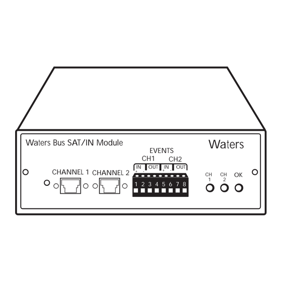
Procedure To connect analog cables: 1. Insert the one end of an analog cable into the CHANNEL 1 port on the Bus SAT/IN module (Figure 2-2). Waters Waters Bus SAT/IN Module EVENTS CHANNEL 1 CHANNEL 2 1 2 3 4 5 6 7 8... -
Page 22: Event In And Out Terminal Strips
In addition, ensure you always connect the shield of the cable to chassis ground at one instrument only. Event In connections The Bus SAT/IN module can accept an inject start signal when an injection occurs. The inject start signal triggers the Bus SAT/IN module to start collecting and converting data. Note: The Bus SAT/IN module requires a pulsed inject start signal. -
Page 23: Removing The Terminal Strip
Procedure To connect event cables: 1. Remove the terminal strip from the Bus SAT/IN module (Figure 2-3). Figure 2-3 Removing the Terminal Strip 2. Connect the two spade connectors at one end of an Event In/Out cable to: • To an injector, for an Event In signal •... -
Page 24: Connecting Event Cables
To Injector 1 to 5 2 to 6 Figure 2-5 Connecting Two-Channel Detector 5. Replace the terminal strip. If the Bus SAT/IN module does not require a BCD cable, proceed directly to Section 2.6, Connecting the Power Supply. Connecting Event Cables... -
Page 25: Connecting Bcd Cable (Optional)
2.5 Connecting BCD Cable (Optional) The BCD (Binary Coded Decimal) connection on the Bus SAT/IN module allows the Bus SAT/IN module to read and record BCD encoded data from Waters autosamplers that support BCD data format. Refer to your autosampler operator’s manual for information about BCD formats. -
Page 26: Connecting The Power Supply
Bus SAT/IN module. Failure to do so may damage the unit. Once the 5-pin connector is attached to the Bus SAT/IN module, do not remove it except to service the module. Connecting the Power Supply... -
Page 27: Chapter 3 Using The Bus Sat/In Module
5-pin connector at the Bus SAT/IN module (see Section 2.6, Connecting Power Supply.). Failure to do so may damage the unit. Once the 5-pin connector is attached to the Bus SAT/IN module, do not remove it except to service the module. -
Page 28: Bus Lac/E Card Dip Switch Positions
(Normal Settings) Figure 3-1 Bus LAC/E Card DIP Switch Positions LED indicators LED indicators on the front panel reflect the status of the Bus SAT/IN module: Table 3-1 Summary of LED Indicators Meaning When Lit Remains lit when powerup sequence is successful. -
Page 29: Configuring The Bus Sat/In Module
• For details on developing an instrument method when using a Bus SAT/IN module, refer to Chapter 6, Creating/Modifying an Instrument Method. 3.3 Troubleshooting If the Bus SAT/IN module does not appear in the instruments list, verify that the DIP switches on the Bus LAC/E card are set to OPEN (Figure 3-1). -
Page 30: Appendix A Bus Sat/In Module Specifications
Appendix A Bus SAT/IN Module Specifications This appendix contain operating specifications for the Bus SAT/IN module. Table A-1 Bus SAT/IN Module Specifications Condition Specification Signal input range –0.25 to 2.25 V Dimensions Bus SAT/IN module 6.33” wide x 9.5” deep x 2.32”... - Page 31 Table A-1 Bus SAT/IN Module Specifications (Continued) Condition Specification Power supply Input, auto-adjust 90 VAC to 265 VAC, 47 to 63 Hz Output +5 VDC, ± 12 VDC Power output (max) 25 watts Typical noise 4 to 6 µV, (RMS) inputs shorted Operating temperature 50 to 95 °F (10 to 35°C)
-
Page 32: Appendix B Spare Parts
Appendix B Spare Parts The following spare parts are recommended for use with the Bus SAT/IN module. Table B-1 Bus SAT/IN Module Spare Parts Item Part Number Bus SAT/IN module, with Startup 200415 Kit and power supply Bus SAT/IN module only... -
Page 33: Appendix C Warranty Information
The foregoing warranty is exclusive and in lieu of all other express and implied warranties, including but not limited to fitness for any other purpose(s). In no event is Waters liable for consequential, economic or incidental damages of any nature. Waters reserves the right not to honor this warranty if the products are abused by the customer. - Page 34 Warranty service Warranty service is performed at no charge and at Waters's option in one of three ways: • A service representative is dispatched to the customer's facility. • The product is repaired at a Waters repair facility. • Replacement parts with appropriate installation instructions are sent to the customer.
-
Page 35: Shipments, Damages, Claims, Returns
findings to support claim. This request must be made within 15 days of receipt. Otherwise, the claim will not be honored by the carrier. Do not return damaged goods to factory without first securing an inspection report and contacting Waters for a return materials authorization number (RMA). - Page 36 Claims After a damage inspection report is secured, Waters will cooperate fully in supplying replacements and handling of a claim which may be initiated by either party. Returns No returns may be made without prior notification and authorization. If for any reason it is...
-
Page 37: Index
flow of data installation power up Millennium 2010 Chromatography Manager serial connections documentation set that include site requirements information about Bus SAT/IN specifications module operation. troubleshooting Modified modular jack connectors Cables Network LAC/E module analog configuring serial ports... - Page 38 Waters 715 UltraWISP event cables Waters 717 Sample Processor Power supply event cables connecting disconnecting Waters Bus LAC/E card. See Bus LAC/E card Power up Waters Bus Satellite Interface Module. See Bus SAT/IN Waters Technical Service Recording serial number Returning damaged shipments...
- Page 39 Artisan Technology Group is your source for quality new and certified-used/pre-owned equipment SERVICE CENTER REPAIRS WE BUY USED EQUIPMENT • FAST SHIPPING AND DELIVERY Experienced engineers and technicians on staff Sell your excess, underutilized, and idle used equipment at our full-service, in-house repair center We also offer credit for buy-backs and trade-ins •...
Need help?
Do you have a question about the Bus SAT/IN and is the answer not in the manual?
Questions and answers