Rotary 100 Series Installation Instructions Manual
Inground lifts
Hide thumbs
Also See for 100 Series:
- Installation instructions manual (120 pages) ,
- Operation and maintenance manual (66 pages) ,
- Operation & maintenance manual (117 pages)
Advertisement
Quick Links
IMPORTANT
instructions other than those shipped with equipment are used. Read all literature
and engineering drawings provided with this lift before installation.
DO NOT Operate Lift
Without Superstructure
© Feb. 2018 by Vehicle Service Group. All rights reserved.
Models:
MOD335-18
MOD335-21
MOD335-24
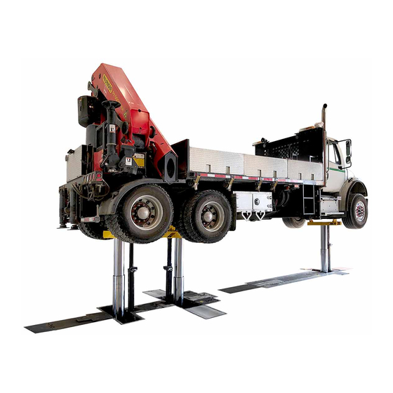
3-POST (100 Series)
INGROUND LIFTS
Capacity 105,000lbs.
35,000 lbs. Each Post
We assume no responsibility for installation errors where
DO NOT Operate Lift
Without Superstructure
Recommended Fluid Specifications for Rotary Lifts
Fluids recommended for use in automotive lifts should
conform to the following specifications.
Viscosity Range: 150 SUS (32CST) ISO32 / 10W
Aniline Point:
210
F Min.
0
Viscosity Index: 95 Min.
Additives:
Anti-Foam
Anti-Rust
Anti-Oxidation
Pour Point:
20
F below operating temp.
0
Tank Capacity:
28 Gallons (MOD35 Series Lifts)
CO10461.2
I
I
N
N
S
S
T
T
A
A
L
L
L
L
A
A
T
T
I
I
O
O
N
N
I
I
N
N
S
S
T
T
R
R
U
U
C
C
T
T
I
I
O
O
N
N
S
S
IN20705
Rev. C 2/19/2018
Advertisement

Related Manuals for Rotary 100 Series


Summary of Contents for Rotary 100 Series
- Page 1 DO NOT Operate Lift Without Superstructure DO NOT Operate Lift Without Superstructure Recommended Fluid Specifications for Rotary Lifts Fluids recommended for use in automotive lifts should conform to the following specifications. Viscosity Range: 150 SUS (32CST) ISO32 / 10W Aniline Point: F Min.
- Page 2 Step 1: Removing Shipping Braces And Cleaning Housings: Top View Of Stationary Housing IMPORTANT Never remove shipping braces before housing has been set and the concrete has cured. Clean Power Unit Brackets Note: Refer to local codes for concrete cure times. Clean Area Where Clean LDS* Rear Post Will...
- Page 3 Check for damage of coating on posts. Contact laying down. This prevents the piston in the post from pushing Rotary Lift if you have any concerns. out too much hydraulic fluid while installing the male adapter and hydraulic hose. This is important to the bleeding procedure done later in the installation.
- Page 4 Step 4: Installing Locking Latch Assemblies And Position Note: Pay attention to the orientation of the post position sensor Sensors To Latch Plates On Posts: mounting. The string protruding out of the top of the sensor goes next to the post. Note: All components can be mounted to the posts before lowering them into the front and rear housings.
- Page 5 Note: When Installing 1/4-20NC x 1/2" Lock Assembly The Flanged Cap Screw Grade 5 Elbow For The Air Line Lock Assembly Faces Away From The Post Attach Air Line Guard To Lock Assembly Bottom of Lock Assembly 3/8-16 x 1-1/2” Lg . HHCS Gd.
- Page 6 Step 6: Installing Recoil Air Hoses: A.) Install recoil air lines per, Fig. 6. B.) Install second air line guard, Fig. 6. A. Install Recoil Air Line Into Union Tee C. Air Line Guard Attaches Here 1/4-20NC x 1/2" Flanged Cap Screw Grade 5 Install Air Line...
- Page 7 Step 7: Attaching Hydraulic Hoses To Posts: Flared Fittings Tightening Procedure IMPORTANT Review Figs. 7, 7a, and 7b thoroughly before 1. Screw the fittings together finger tight. Then, tighten installing hydraulic hoses. to 85 ft lbs or (1-1/4 hex flats). A.) Remove plugs in posts (A.), Fig.
- Page 8 IMPORTANT Hydraulic Hoses Should Be Installed Stationary Post With Posts Laying down. Laying Posts Down Prevents The Piston In The Post From Pushing Out Too Much Hydraulic Fluid While Installing The Male Adapter And Hydraulic Hose. This Is Important To The Bleeding Procedure Done Later In The Installation.
- Page 9 Step 8: Lowering Moveable Posts Into Housings: A.) Take the posts with the longer hoses and lower them into the front and rear housings, Fig. 8. Step 9: Moving Post To Saddle Pocket: A.) Roll post back into saddle pocket. IMPORTANT Use Post Lugs On Lower Post Assembly...
- Page 10 Step 10: Installing Stationary Post Into Housing: A.) Lower post into housing, Fig. 9. Align Post With Holes In Lower Post With 60" Post Bracket Hydraulic Hose Into Stationary Housing Locking Latch Plate Faces Away From Power Unit Power Unit Area Area CAUTION...
- Page 11 Step 11: Mounting The Position Sensors To Position Sensor Step 12: Placing The Position Sensors And Brackets Onto The Adapter Brackets: Power Unit Brackets In Moveable Post Housings: A.) Mount the position sensor to the position sensor adapter bracket, Fig. 10, with 1/4"-20NC x 1" HHCS and nylon insert lock A.) Attach data cable to horizontal string pot then lower the nuts.
-
Page 12: Power Unit
Check Valve Rotate 45° Towards Housing IMPORTANT Several types of motors are used on the hydraulic tank assemblies. Adjustments may be needed to the check valve if it rubs against the power unit. Junction The check valve should only be rotated just enough to keep it from rubbing against the power unit. - Page 13 Step 14: Installing Power Unit Into Stationary Post Housing: A.) Make adjustments to power unit for stationary housing, Fig. 13. B.) Lower power unit into stationary housing with elbow on check valve assembly facing towards post, Fig. 13a. Elbow Rotate 45° Towards Junction Adjustments Must Be Made To The Rear Housing Power Unit.
- Page 14 Step 15: Attaching Hydraulic Hoses To Power Units: Flared Fittings Tightening Procedure A.) Review flared fittings tightening procedure for hydraulic hose swivel nuts, Fig. 14. 1. Screw the fittings together finger tight. Then, tighten to 85 ft lbs or (1-1/4 hex flats). B.) Attach hydraulic hose in front and rear housing to power unit, Fig.
- Page 15 C.) Attach hydraulic hose in stationary housing. Make sure that Stationary Housing the elbow on check valve assembly is turned 45° , Fig 14b. JIC Flare Fitting Attach Hydraulic Hose To Check Valve Assembly On Power Unit Fig. 14b Step 16: Installing The Motor Chain Drive Assembly Lower Motor Chain Drive Into Moveable Post Housings: Assembly Into Moveable Housing...
- Page 16 Step 17: Installing LDS (Liquid Detection System) Components: B.) Install the LDS components in the stationary housing, bracket is located next to power unit, Fig. 16a. A.) Install the LDS components in the moveable post housings to the bracket located next to the motor drive chain assembly, Fig.16. M o v e a b l e P o s t H o u s i n g 1"...
- Page 17 Step 18: Filling Power Unit Tanks: Recommended Fluid Specifications for Rotary Lifts Fluids recommended for use in automotive lifts should A.) Fill power unit tanks with ISO 32 fluid (see Fig. 17 for fluid conform to the following specifications. specifications.)
- Page 18 Overview Of Connections From Control Panel To Components. Wall Mounted Option Shown. For MOD335 Lifts (3-Post). Type MC-HL Metal - Clad Cable, 4 Conductor, 600V Minimum, For Use In Class 1, Div. 1, Hazardous Locations. Fittings Must Be Compatible With Cable And Suitable For Class 1, Div. 1, Hazardous Locations From Outlet Boxes To Electric Motors In Housings (See Wiring Schematic).
- Page 20 ANCHOR REQUIREMENTS: HARDWARE PROVIDED BY INSTALLING CONTRACTOR...
- Page 21 This method Seal Off, Supplied Wall is not to be construed as the only method of doing By Rotary. Attach so. Always check codes and regulations before Cable Ground To proceeding. Motor Ground Terminal.
- Page 22 Step 20: Connecting Position Sensor Cables: C.) Route horizontal position sensor cable and the rise position sensor cable through the conduit and plug them into their A.) Remove the screw from the upper enclosure of the control appropriate sensor, see Fig. 20 and Fig. 21. Sensors only plug in panel.
- Page 23 Route Position Sensor Cables From Control Panel, Through Conduit And Around Drive Chain Assembly And Through Guides In Housing Route To Connections In Upper Enclosure Note: Of Control Panel Schematics provided For Position Sensor in back of manual Moveable Post 1 Moveable Post 2 Plug Position Sensor Cable Into Position Sensor...
- Page 24 VP = Vertical Position HP = Horizontal Position Install High Integrity Ground Connection For Instrinsically Safe Postion Sensor System Refer To System Wire Diagram Notes: Black 1 Shielded Wire Green Yellow Black 2 Black 1 Shielded Wire Green Yellow Black 2 Black 1 Shielded Wire Green Yellow...
- Page 25 Step 21: Making Air Line Connections Into Housings: B.) Route (4) 1/4" air lines through service conduits and make connections per Figs. 22 thru 24. A.) Review Fig. 28a. Determine lift configuration to control panel. Notice (1) is always to the left when viewing lift from behind IMPORTANT A filter/regulator must be installed on air supply control panel.
- Page 27 Fig. 24...
- Page 28 Step 23: Installing Chain Idler Assemblies: NOTE: Notice in Fig. 25 that the sprockets will be facing downward into housing. A.) Moveable Post Housings - Install chain idler brackets to frames with (4) 1/2" - 13NC x 1-1/2" HHCS, Fig. 25. Holes are Step 24: Installing Drive Chains Into Moveable Post Housings: located between the slots in the C-channel where the posts were lowered into the housings, Fig.
- Page 29 B.) Route drive chain around sprocket on motor chain drive assembly and sprocket on chain idler assembly and attach other end to of drive chain to axle/chain adjustment bracket with 1/2"- 13NC hex nylon insert lock nut, Fig. 26. C.) Repeat steps A and B for other drive chain. IMPORTANT After drive chains have been installed slack in chains should not exceed 1", see Fig.
- Page 30 Step 25: Installing Shutter Plate Ramps And Wheel Stops Into B.) Install wheel stops (1) on each side of the power unit. Holes Front Housing : for wheel stops are located on the post side of the power unit. A.) Install shutter plate ramps into front housing, Fig. 27. NOTE: Curves on shutter plate ramps face outward away from post.
- Page 31 Step 26: Making Electrical Connections In The Control Panel: Step 27: Detailing Air Lines And Cables: A.) Before making wire connections, review Fig. 28a. This will A.) Inspect and wire tie all air lines and cables pulling any excess help determine lift configuration to control panel. Notice that (M1) to the control panel.
- Page 32 Lift Current "X" Mark Model Electrical Service Required Required Disconnect MC2-208V 208V, 3Ph., 60Hz. 33 Amp. MC2-230V 230V, 3Ph., 60Hz. 32 Amp. MC2-460V 460V, 3Ph., 60Hz. 16 Amp. MC2-575V 575V, 3Ph., 60Hz. 12.8 Amp. MC3-208V 208V, 3Ph., 60Hz. 62 Amp. MC3-230V 230V, 3Ph., 60Hz.
- Page 33 Console Pendant Connection Connection Brown Brown White White Black Black White White Pendant storage hook Pendant Cable Connector (cover removed) Pendant Cable can route through top or bottom of Pendant Pendant Cable routes through a 7/8” hole on the side of console DO NOT USE PENDANT BELOW FLOOR LEVEL 4"...
- Page 34 Step 28: Installing Saddles To Posts: A.) Attach saddles to front, middle, and rear posts, Fig. 29. B.) Attach post position sensors to 5/16" stud on saddles, Fig. 29. Do Not Operate Lift Without Superstructure IMPORTANT Install (1)3/4"-10NC x 2-1/4" HHCS GR 8 IMPORTANT Torque To 100 ft/lbs Install (6) 7/8"-9NC x 5"...
- Page 35 Step 29: Powering Up The Control Panel: IMPORTANT Verify that memory card marked "service" is installed in upper enclosure of control panel. If it is not installed refer to the operations manual of changing out memory cards. 1234 SERVICE Never change memory cards with IMPORTANT power on to control board.
- Page 36 Step 30: Becoming Familiar With Post Functionality: Lift Configuration A.) To access Service Menus, the service memory card must be installed. Service Menu Summary MENU SUB-MENU DESCRIPTION [0,1]* Pocket Stop [0,1]* Home Stop [0,1]* Floor Level Stop [0,1]* Adjustable End Stop [0,1]* Light Indicator Limit [0,1]*...
- Page 37 Step 31: Bleeding Posts (One Post At A Time): Step 32: Leveling The Posts And Locking Leg Assembly: A.) Bring post to full rise. (Let set at full rise for several minutes). A.) Bring posts to full rise and check with a machinist level, Fig. B.) Turn bleeder screw on top of post counter clockwise until fluid flows out of post, Fig.
- Page 38 Step 33: Floor Level Feature Instructions, Fig. 42 and 43: 1.) Move all posts completely down into their home pockets (see The floor level feature is designed to automatically stop the jacks “home pocket calibration” point below). Make sure there is equal at floor level as they are raising out of their pockets or lowering space around the saddles.
- Page 39 Floor Level Operation, Fig. 44: Once a floor stop has been calibrated for the moveable post, horizontal movement is only allowed at the floor stop level. When both jacks are raised in “all” mode from below floor level, or lowered from above floor level, they will automatically stop at their individual floor levels.
- Page 40 Auto-wheelbase option, Fig. 45: 3.) Press up on the joystick. When a vehicle profile is selected, auto-wheelbase will enable -All posts will move to floor level. When moveable posts reach automatic movement of the lift posts to the wheelbase setting, as the floor level, they will pause slightly, then continue moving well as automatic return to pocket.
- Page 41 Step 46: Installing Shutter Plates In Moveable Housings: D.) As you get close to the shutter plate ramps install suspension chains on the hangers of the shutter plate ramps, Fig. 49. Note: Run Post the length of the track several time and make sure everything is working properly before installing shutter plates, Fig.
- Page 42 Step 47: Installing Cover Plates To Moveable Post Housings: Flat SHCS, Drain faces away from post, Fig. 51. A.) Install clean out tubes to end cover plates. C.) Install top plate assembly with (2) 3/8"-16NC x 3/4" button head SHCS, Fig. 51. B.) Install center cover plates to post cover plates with hinge pins, Fig.
- Page 43 Hang Chains Off Of Hooks On Ramps Suspension Chains Hanging From Ramps 5/16" Push Nut Fig. 49 Install Clean Out Tube Into Coupling By Gearbox Before Installing End Cover Plate Into Moveable Post Housing Clean Out Coupling Tube Gear Box End Cover Plate Held With...
- Page 44 (4) 3/8”-16NC x 3/4” Flat SHCS 1: Install Clean Out Tube 2: Install Front Filler Plate 3: Install Splash Guard (2) 3/8”-16NC x 3/4” 4: Install Rear Filler Plate Button Head SHCS Front Filler Plate Clean Out Tube Fig. 51 4: Install Splash Guard and Center Cover 5: Install Right End Plate 6: Install Left End Plate...
- Page 48 Pneumatic Schematic For Stationary And Movable Housings Stationary Piston Movable Piston Power Unit Power Unit Check Valve Check Valve Lock Air Cylinders Quick Exhaust Valve Lock Air Cylinders Quick Exhaust Valve Return Return Pressure Air Line Air Line Regulator (90psi Maximum) Directional Sensing...
-
Page 49: Hydraulic Schematic
Hydraulic Schematic Customer Connections Fuse... - Page 50 NOTES...
- Page 51 NOTES...
- Page 52 Installer: package, and give to lift owner/operator. Thank You Trained Operators and Regular Maintenance Ensures Satisfactory Per- formance of Your Rotary Lift. Contact Your Nearest Authorized Rotary Parts Distributor for Genuine Rotary Replacement Parts. See Literature Package for Parts Breakdown.
Need help?
Do you have a question about the 100 Series and is the answer not in the manual?
Questions and answers