Table of Contents
Advertisement
Quick Links
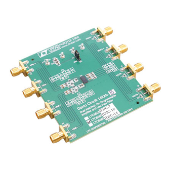
DESCRIPTION
Demonstration circuit 1659A features the LT
side current sense amplifier with two comparators and a
400mV reference.
The demo board circuit amplifies the voltage across an
on-board current sense resistor, to provide a precision
unipolar voltage output that is proportional to the sensed
current. The board has two on-board comparators with
latching outputs and an integrated 400mV reference that
sets the threshold for the comparators. There are two ver-
sions of this demonstration circuit, A and B, depending on
which version of the LT6109 is installed. The DC1659A-A
(LT6109-1) has an inverting and a noninverting compara-
tor input available, while the DC1659A-B (LT6109-2) has
PERFORMANCE SUMMARY
SYMBOL
PARAMETER
V
Input Supply Range
IN
V
Measured Output Signal
IOUT
I
Measured Output Current
IOUT
I
Output Load Current Range
LOAD
I
IN Quiescent Current
Q
V
Comparator1 Threshold
THR1
V
Comparator2 Threshold
THR2
OPERATING PRINCIPLES
The LT6109 operates by amplifying the voltage drop across
a sense resistor that is in series with the load. The sense
inputs of the amplifier differentially measure the sense
resistor voltage drop to control an internal variable current
source that allows translation of the input voltage level to
a level referenced to the GND. The circuit gain is set by
Arrow.com.
Downloaded from
DEMO MANUAL DC1659A
High Side Current Sense
Amplifiers with Reference
®
6109, a high
two inverting inputs available. Both current sense gain
and current fault limits are set by on board resistors and
are the same for both boards. The gain is set at 100V/V
and the comparators are set to trip at current thresholds
of 50mA and 300mA.
The key performance specifications are listed in the table
below.
Design files for this circuit board are available at
http://www.linear.com/demo
L, LT, LTC, LTM, TimerBlox, Linear Technology and the Linear logo are registered trademarks
of Linear Technology Corporation. All other trademarks are the property of their respective
owners.
(T
= 25°C)
A
CONDITIONS
I
= 100mA
LOAD
V
= 1V
IOUT
Thermal Limit of R
SENSE
V
= 12V
IN
V
= 3.0V
IOUT
V
= 0.5V
IOUT
the ratio of the output resistor to the input resistor. The
comparator thresholds are set by the internal reference
and the current trip points are set by dividing the output
resistance into a network of three resistors. The DC1659
is shipped with a 100mΩ sense resistor, a gain of 100 and
current fault thresholds of 50mA and 300mA.
LT6109-1/LT6109-2
and Comparators
MIN
TYP
MAX
2.7
60
1
100
800
300
50
UNITS
V
V
μA
4
A
μA
mA
mA
dc1659af
1
Advertisement
Table of Contents

Related Manuals for Linear Technology DC1659A


Summary of Contents for Linear Technology DC1659A
- Page 1 A and B, depending on which version of the LT6109 is installed. The DC1659A-A L, LT, LTC, LTM, TimerBlox, Linear Technology and the Linear logo are registered trademarks of Linear Technology Corporation. All other trademarks are the property of their respective (LT6109-1) has an inverting and a noninverting compara- owners.
- Page 2 DEMO MANUAL DC1659A BLOCK DIAGRAMS LT6109-1 (DC1659A-A) LT6109-2 (DC1659A-B) LT6109-1 LT6109-2 100Ω 100Ω SENSEHI SENSEHI – – SENSELO SENSELO OUTA OUTA – – – – – – 200nA 200nA EN/RST EN/RST ENABLE AND ENABLE AND RESET TIMING RESET TIMING RESET...
- Page 3 DEMO MANUAL DC1659A QUICK START PROCEDURE The DC1659A provides a simple way to evaluate the 4. Turn on the power supply. The comparators start in an performance of the LT6109. Refer to Figure 1 for proper unknown state and must be reset. This can be done measurement equipment setup and follow the procedure by pressing the reset button.
- Page 4 DEMO MANUAL DC1659A OPERATION Current Sense Gain Optional Settings The gain of the LT6109 current sense amplifier is set 1. For supply voltages below 3.3V, remove R20 and install by the ratio of R and R resistors. In the demo R21 (0Ω...
-
Page 5: Parts List
DEMO MANUAL DC1659A PARTS LIST ITEM REFERENCE PART DESCRIPTION MANUFACTURER/PART NUMBER Capacitor, 1μF 20% 1206 100V X7R TDK/C3216X7R2A105M Capacitor, 0.47μF 20% 0603 16V X5R AVX/0603YD474MAT2A C4, C5 Capacitor, 0.1μF 20% 0402 10V X5R Taiyo Yuden/LMK105BJ104MV-F Capacitor, 0.1μF 20% 0603 X5R Optional Capacitor, 0.1μF 10% 0603 100V X7R... - Page 6 DEMO MANUAL DC1659A SCHEMATIC DIAGRAM dc1659af Arrow.com. Arrow.com. Arrow.com. Arrow.com. Arrow.com. Arrow.com. Downloaded from Downloaded from Downloaded from Downloaded from Downloaded from Downloaded from...
- Page 7 Information furnished by Linear Technology Corporation is believed to be accurate and reliable. However, no responsibility is assumed for its use. Linear Technology Corporation makes no representa- tion that the interconnection of its circuits as described herein will not infringe on existing patent rights.
- Page 8 Linear Technology Corporation (LTC) provides the enclosed product(s) under the following AS IS conditions: This demonstration board (DEMO BOARD) kit being sold or provided by Linear Technology is intended for use for ENGINEERING DEVELOPMENT OR EVALUATION PURPOSES ONLY and is not provided by LTC for commercial use. As such, the DEMO BOARD herein may not be complete in terms of required design-, marketing-, and/or manufacturing-related protective considerations, including but not limited to product safety measures typically found in finished commercial goods.
Need help?
Do you have a question about the DC1659A and is the answer not in the manual?
Questions and answers