Advertisement
DESCRIPTION
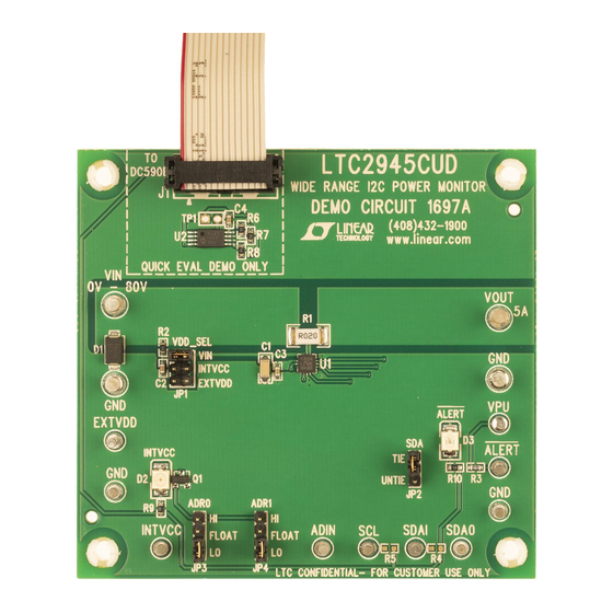
Demonstration circuit 1697A features the LTC2945. The
LTC2945 is a rail-to-rail system monitor that measures
current, voltage, and power. It features an operating range
of 2.7V to 80V and includes a shunt regulator for supplies
above 80V to allow flexibility in the selection of input sup-
ply. The current common mode measurement range of
0V to 80V is independent of the input supply. An onboard
0.75% accurate 12-bit ADC measures load current, input
voltage and an auxiliary external voltage. A 24-bit power
value is generated by digitally multiplying the measured
12-bit load current and input voltage data. Minimum and
BOARD PHOTO
4V TO 80V
DEMO MANUAL DC1697A
Wide Range I
maximum values are stored and an overrange alert with
programmable thresholds minimizes the need for software
polling. Data is reported via a standard I
demo board is populated for a 5A application. This can
be changed by populating R1 accordingly.
Design files for this circuit board are available at
http://www.linear.com/demo
L, LT, LTC, LTM, QuikEval, Linear Technology and the Linear logo are registered trademarks of
Linear Technology Corporation. All other trademarks are the property of their respective owners.
TO DC590
Figure 1. Proper Test Equipment Setup
LTC2945
2
C Power Monitor
2
C interface. The
LOAD
dc1697A F01
dc1697af
1
Advertisement
Table of Contents

Related Manuals for Linear Technology DC1697A


Summary of Contents for Linear Technology DC1697A
- Page 1 0.75% accurate 12-bit ADC measures load current, input L, LT, LTC, LTM, QuikEval, Linear Technology and the Linear logo are registered trademarks of voltage and an auxiliary external voltage. A 24-bit power Linear Technology Corporation. All other trademarks are the property of their respective owners.
-
Page 2: Quick Start Procedure
5V to 80V and produces 5V for INTVCC when above 7V. The DC1697A was designed to be connected to the DC590 and controlled through the QuikEval suite of software. All INTVCC: Internal Low Voltage Supply Input/Output. This... -
Page 3: Hardware Setup
5V supply should be provided at the INTVCC turret. This is illustrated in the following figures. In order for the DC1697A to function, power must be applied. If the VDD_SEL jumper is set to VIN, then V If the system is connected properly, the INTVCC green LED should be lit and the ALERT red LED should be off. - Page 4 35mA 1mA +I LOAD(MAX) Jumper VDD_SEL Set to INTVCC With A Resistor Connected from DC1697 GND to Circuit Ground > 80V dc1697A F03 Figure 3. Powering DC1697A Using High-Side Shunt Regulator to Allow for Input Voltage Higher Than 80V dc1697af...
- Page 5 DEMO MANUAL DC1697A HARDWARE SETUP Jumper VDD_SEL Set to INTVCC with a Resistor Connected to INTVCC 0V TO 80V LOAD dc1697A F04 > 80V Figure 4. Powering DC1697A Through Low-Side Shunt Regulator in High-Side Current Sense Topology dc1697af...
- Page 6 DEMO MANUAL DC1697A HARDWARE SETUP Jumper VDD_SEL set to EXTVDD with the –48V input tied interface is operating at –48V with respect to –48V RTN, to VIN and GND and the –48V Return tied to EXTVDD. The which is normally at earth ground potential.
-
Page 7: Software Setup
VIN measurement. RSense With Alert Persist not enabled, an alert event will still light is set to 20mΩ by default on the DC1697A, should any up the corresponding FAULT button, however the ALERT changes be made to the board, the corresponding value LED on the board will turn on briefly before turning off due should be entered into the Software GUI. - Page 8 DEMO MANUAL DC1697A PARTS LIST ITEM REFERENCE PART DESCRIPTION MANUFACTURER/PART NUMBER Cap., X7R, 0.1μF, 100V, 10%, 1206 AVX 12061C104KAT2A Cap., X7R, 1000pF, 100V, 10%, 0603 AVX 06031C102KAT2A C3, C4 Cap., X5R, 0.1μF, 25V, 20%, 0603 AVX 06033D104KAT2A Voltage Supressor, 75V...
-
Page 9: Schematic Diagram
Information furnished by Linear Technology Corporation is believed to be accurate and reliable. However, no responsibility is assumed for its use. Linear Technology Corporation makes no representa- tion that the interconnection of its circuits as described herein will not infringe on existing patent rights. - Page 10 Linear Technology Corporation (LTC) provides the enclosed product(s) under the following AS IS conditions: This demonstration board (DEMO BOARD) kit being sold or provided by Linear Technology is intended for use for ENGINEERING DEVELOPMENT OR EVALUATION PURPOSES ONLY and is not provided by LTC for commercial use. As such, the DEMO BOARD herein may not be complete in terms of required design-, marketing-, and/or manufacturing-related protective considerations, including but not limited to product safety measures typically found in finished commercial goods.
Need help?
Do you have a question about the DC1697A and is the answer not in the manual?
Questions and answers