Table of Contents
Advertisement
Quick Links
Description
The DC1605B is a demonstration system that showcases
the
LTC
2936, a 6-channel I
®
with EEPROM. The LTC2936 simultaneously monitors up
to six power supply voltages and detects undervoltage and
overvoltage conditions. In addition the LTC2936 monitors
two GPI pins and is able to drive three GPIO pins to indicate
OV, UV, system reset, system alert, or other control signal.
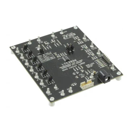
The DC1605B is a single circuit board that contains the
LTC2936 and support circuitry to provide the ability to dem-
onstrate features and capabilities of the LTC2936 without
the need for external power supplies. The DC1605B demo
board provides an accurate voltage supervision of six chan-
nels and offers over/undervoltage thresholds in various
ranges and increments that are digitally programmable.
This demonstration system is supported by the
LTpowerPlay™ graphical user interface (GUI) which en-
ables complete control of all the features of the device.
Together, the LTpowerPlay software and DC1605B hard-
ware system create a powerful development environment
for designing and testing configuration settings of the
LTC2936. These settings can be stored in the device's
internal EEPROM or in a file. This file can later be used
to order pre-programmed devices or to program devices
in a production environment. The software displays all of
the configuration settings and real time measurements
from the system supervisor and peripheral ICs. Telemetry
allows easy access and decoding of the fault log created
by the LTC2936. The board comes pre-programmed with
the EEPROM values appropriate for the six power supply
rails on the DC1605B. Just plug and play!
The LTC2936 chip is mounted on the topside of the board
with support ADC and DAC circuitry on the back.
The ADC provides voltage readings for all six voltage
supervisor inputs on the LTC2936 and also reads the GPI
and GPIO voltages. The DAC drives six programmable
voltages that are used to emulate the user's system rails.
The extra support circuitry allows the user to evaluate
2
C/SMBus voltage supervisor
DEMO MANUAL DC1605B
Programmable Hex
Voltage Supervisor Featuring
the LTC2936 with EEPROM
the LTC2936 quickly and without the need for external
voltmeters or power supplies.
The DC1605B demo board can be powered by an external
power supply, such as a 12VDC supply. Communication
with the software is provided through the DC1613 USB-to-
2
I
C/SMBus/PMBus Controller. The following is a checklist
of items which can be obtained from the LTC website or
LTC Field Sales.
2
USB-to-I
C/SMBus/PMBus Controller (DC1613)
n
LTpowerPlay Software
n
DC1605B Features
Supervise Six Power Supplies
n
Powered from USB Dongle, Power Jack, or V
n
2
I
C Adjustable OV/UV Trip Points
n
Guaranteed Threshold Accuracy: ±1%
n
2
I
C/SMBus Serial Interface
n
Internal EEPROM
n
Six Comparator Outputs
n
256 Programmable Thresholds per Channel
n
Up to Three Range Settings per Channel
n
Two General Purpose Inputs
n
Three General Purpose Inputs/Outputs
n
Programmable Output Delays
n
Autonomous Operation without Additional Software
n
Supported by LTpowerPlay GUI
n
LTC2936 Available in 24-Lead QFN and SSOP Packages
n
Design files for this circuit board are available at
http://www.linear.com/demo/DC1605B
L, LT, LTC, LTM, Linear Technology and the Linear logo are registered trademarks and
LTpowerPlay is a trademark of Linear Technology Corporation. All other trademarks are the
property of their respective owners.
IN
dc1605bf
1
Advertisement
Table of Contents

Related Manuals for Linear Technology DC1605B


Summary of Contents for Linear Technology DC1605B
- Page 1 L, LT, LTC, LTM, Linear Technology and the Linear logo are registered trademarks and The extra support circuitry allows the user to evaluate LTpowerPlay is a trademark of Linear Technology Corporation. All other trademarks are the property of their respective owners.
-
Page 2: Performance Summary
DEMO MANUAL DC1605B performance summary Specifications are valid over the full operating temperature range. Common Characteristics PARAMETER CONDITIONS UNITS Supply Input Voltage Range 13.9 DD33 V1 to V6 Threshold Accuracy ±1.0 V1 to V6 Monitoring Range Precision Range Low Range Medium Range Table 1. -
Page 3: Theory Of Operation
DEMO MANUAL DC1605B theory of operation GENERAL DESCRIPTION The LTC2936 is a hex voltage supervisor which detects an overvoltage or undervoltage and signals the system of a fault condition. The chip has a dedicated power supply pin, V , and has an internal 3.3V regulator. The chip... - Page 4 LTC2936 simply makes a comparison to each of the Vn The LTC2936 chip is mounted on the topside of the board input voltages. The simplest demonstration of the DC1605B with support ADC and DAC circuitry on the back. The sup- is to power and control the board via the DC1613 USB port circuitry is powered from 5V.
-
Page 5: Powering The Board
To read the RAM registers into the GUI, click the independent of the jumper settings. “R” RAM-to-PC icon in the toolbar. The DC1605B uses a multiplexed ADC that is used to DC1605B LEDs provide voltage readback values. The telemetry plot in the GUI is similar to a multichannel oscilloscope which is The DC1605B board has two green LEDs. - Page 6 The ToolWindow is automatically populated when LTpowerPlay detects the DC1605B demo board when it starts. Note that when you save a project, the DAC settings are saved in the project file. dc1605bf...
- Page 7 LTC2936 6-channel voltage supervisor. The software gets, including the DC1605B demo system or a customer supports a variety of different tasks. You can use LTpow- board. The software also provides an automatic update...
-
Page 8: Quick Start Procedure
2. Remove the board from the ESD protective bag and place it on a level surface. Connect the DC1613 I SMBus/PMBus controller to the DC1605B board using the 12-pin ribbon cable. Figure 4. Connecting DC1605B Board and the DC1613 USB to I C/SMBus/PMBus Controller dc1605bf... -
Page 9: Saving A Configuration
QUICk START VIDEO There is a Quick Start Video that covers the basic features of the LTC2936 chip and DC1605B demo board. The video can be accessed via LTpowerPlay by navigating to the Help menu > DC1605B Content. - Page 10 DEMO MANUAL DC1605B Dc1605B Details – top siDe Figure 5. DC1605B Top Side Details Table 2. Default Jumper Configuration REFERENCE DESIGNATOR SIGNAL NAME USAGE DEFAULT JP1 – JP6 V1 – V6 Selects internal vs external voltage JP7, JP8 ASEL1, ASEL0...
- Page 11 DEMO MANUAL DC1605B Demo BoarD use cases USE CASE #1 A common configuration for the LTC2936 dedicates the V1 pin to the highest supply in the system and uses V2-V6 to monitor other voltages. The V1 pin provides power to the chip and also is used to detect an OV or UV on the V1 pin.
- Page 12 ALERT. Press the MR pushbutton on GPI1 to release GPIO2 back high (LED blue). USE CASE #2 The DC1605B demo board can be configured to supervise external supply voltages. Inputs V1-V6 may be used for this purpose. Simply move the jumper from INT to EXT...
- Page 13 DEMO MANUAL DC1605B Demo BoarD use cases USE CASE #3 3. Configure GPIO1 as active-low with weak pull-up. To update the changes made in steps 1-3, click the Write Another common configuration is one that uses a GPIO All Registers (PC → RAM) icon.
- Page 14 DEMO MANUAL DC1605B Dc1605B Details – top GPI PUSHBUTTON TEST POINT TURRETS FOR GPI1–2 SIGNALS SWITCHES SLAVE ADDRESS JUMPERS TEST POINT TEST POINT TURRETS FOR TURRETS FOR V1 – V6 GPO1–3 CMP1-6 HEADER V1 – V6 JUMPERS TURRET AND LED...
- Page 15 DEMO MANUAL DC1605B Dc1605B Details – Bottom dc1605bf...
-
Page 16: Parts List
DEMO MANUAL DC1605B parts list ITEM QTY REFERENCE PART DESCRIPTION MANUFACTURER/PART NUMBER Required Circuit Components IC PROG HEX VOLT SUPERVISOR EEPROM SSOP-24 LINEAR: LTC2936CGN#PBF Additional Demo Board Circuit Components C1, C2, C3, C4, C5, C6, C8, C9, C10, C11, CAP CER 10nF 25V 10% X7R 0603... -
Page 17: Schematic Diagram
DEMO MANUAL DC1605B schematic DiaGram dc1605bf... - Page 18 DEMO MANUAL DC1605B schematic DiaGram dc1605bf...
- Page 19 Information furnished by Linear Technology Corporation is believed to be accurate and reliable. However, no responsibility is assumed for its use. Linear Technology Corporation makes no representa- tion that the interconnection of its circuits as described herein will not infringe on existing patent rights.
- Page 20 Linear Technology Corporation (LTC) provides the enclosed product(s) under the following AS IS conditions: This demonstration board (DEMO BOARD) kit being sold or provided by Linear Technology is intended for use for ENGINEERING DEVELOPMENT OR EVALUATION PURPOSES ONLY and is not provided by LTC for commercial use. As such, the DEMO BOARD herein may not be complete in terms of required design-, marketing-, and/or manufacturing-related protective considerations, including but not limited to product safety measures typically found in finished commercial goods.
Need help?
Do you have a question about the DC1605B and is the answer not in the manual?
Questions and answers