Advertisement
Quick Links
Description
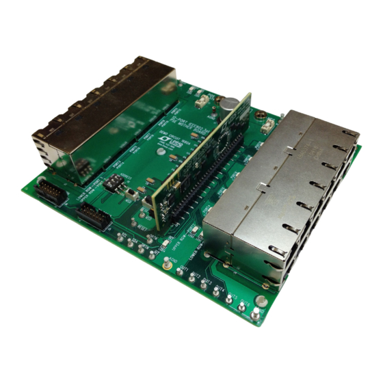
Demonstration kit DC1840B is a 12-port Type 2 power
sourcing equipment (PSE) composed of a DC1682B
daughter card and DC1680A mother board. The kit is
used for evaluation of the LTC4270B and LTC4271 PSE
chipset. Up to 12 powered devices (PDs) can be con-
nected and powered from this system using a single power
supply. A DC590B is connected to the DC1840B for I
interfacing with QuikEval™. This demonstration manual
provides a Quick Start Procedure, a DC1682 overview,
BoarD photo
DEMO MANUAL DC1840B
DC1682B and DC1680A
12-Port PSE with Digital Isolation
a DC1680 overview, schematics, and layout printouts.
Other available supporting documents for the DC1840
are the LTC4270/LTC4271 Layout Guide and the LTC4271
PSE Demo Software Users Manual.
Design files for this circuit board are available at
http://www.linear.com/demo
2
C
L, LT, LTC, LTM, Linear Technology and the Linear logo are registered trademarks and
QuikEval is a trademark of Linear Technology Corporation. All other trademarks are the property
of their respective owners.
LTC4270/LTC4271
dc1840bfc
1
Advertisement

Related Manuals for Linear Technology DC1682B


Summary of Contents for Linear Technology DC1682B
- Page 1 A DC590B is connected to the DC1840B for I L, LT, LTC, LTM, Linear Technology and the Linear logo are registered trademarks and interfacing with QuikEval™. This demonstration manual QuikEval is a trademark of Linear Technology Corporation. All other trademarks are the property provides a Quick Start Procedure, a DC1682 overview, of their respective owners.
-
Page 2: Quick Start Procedure
DEMO MANUAL DC1840B Quick start proceDure Demonstration kit DC1840B includes the DC1682 4. On the DC1680, connect a supply with the positive daughter card and DC1680 mother board. The kit is set rail to POS and negative rail to NEG (Figure 3). Use a up for evaluating the LTC4270/LTC4271. - Page 3 DEMO MANUAL DC1840B Quick start proceDure Figure 1. DC1682 Backside. Setting AUTO and MID Jumpers Figure 2. Inserting the DC1682 into J1 of the DC1680 dc1840bfc...
- Page 4 DEMO MANUAL DC1840B Quick start proceDure Figure 3. DC1840 Basic Setup Figure 4. System Setup with the DC590, DC1680, DC1682 and 55V Power Supply dc1840bfc...
- Page 5 12-port power sourcing equipment (PSE) controller designed for use in IEEE 802.3at Type 1 and Type 2 (high The DC1682B demonstrates proper LTC4270/LTC4271 power) compliant Power over Ethernet (PoE) systems. A board layout that is approximately the height and width transformer isolated communication protocol replaces of a 2 ×...
- Page 6 LTC4270/LTC4271 Layout Guide document when laying ence and are isolated from the analog PoE supply. A 3.3V out the board. supply for V and an isolated V supply are connected to the DC1682B through the 34-pin connector. 34-PIN CONNECTOR DD33 DC1682B SIDE DC1680A SIDE SUPPLY –...
- Page 7 AD6, AD3, AD2, AD1, and AD0 pins J2, PIN 10 XIO0 respectively. On the DC1682B, AD0 and AD1 are tied low with pull-down resistors. AD2, AD3 and AD6 are brought DC1840B F08 out to the 34-pin connector (Figure 7) and set with three switches on the DC1680.
- Page 8 These S1B diodes are placed on the DC1680 mother board of the DC1840 kit. For quick PSE evaluation in AUTO pin mode with MIDSPAN disabled, set JP1 HI and JP2 LO on the DC1682B. 34-PIN CONNECTOR...
- Page 9 AGND. If an external DC1680A, verify all supplies and LEDs are off. Push the 3.3V supply is to be used, contact Linear Technology Ap- card straight down for insertion or pull straight up for plications for proper connection.
- Page 10 DEMO MANUAL DC1840B Demonstration circuit 1680a operation MSD and RESET Pushbuttons Pushbutton switch SW2 when pressed pulls the maskable shutdown input (MSD) pin of the daughter card logic low. Pushbutton switch SW1, when pressed, pulls the RESET When pressed, all ports that have their corresponding mask pin of the daughter card logic low.
- Page 11 DEMO MANUAL DC1840B Demonstration circuit 1680a operation Interrupt LED Port 1 Through 12 Power LED Indicators A red LED indicates when the INT line is pulled logic low Each PSE port has a green LED indicator to show when by the daughter card. When the interrupt is cleared (high) PoE power is present at the port.
- Page 12 Figure 14. DC1680 and DC1682 System Setup with Power Supply, DC590 and PD Demo Board Table 2. DC1840 Kit Versions VERSION FEATURES DC1840A DC1680A, Mother Board with Integrated Magjack DC1682A, 12-Port PSE Daughter Card DC1840B DC1680A, Mother Board with Integrated Magjack DC1682B, 12-Port PSE Daughter Card with Increased Surge Protection dc1840bfc...
- Page 13 DEMO MANUAL DC1840B Demonstration circuit 1682a Layout Top Assembly Layer 1: Top Layer Layer 2: V Plane 1 dc1840bfc...
- Page 14 DEMO MANUAL DC1840B Demonstration circuit 1682a Layout Layer 3: V Plane 2 Layer 4: Bottom Layer Bottom Assembly dc1840bfc...
- Page 15 DEMO MANUAL DC1840B Demonstration circuit 1680a Layout Top Silkscreen dc1840bfc...
- Page 16 DEMO MANUAL DC1840B Demonstration circuit 1680a Layout Layer 1: Top Layer dc1840bfc...
- Page 17 DEMO MANUAL DC1840B Demonstration circuit 1680a Layout Layer 2: AGND, CGND Plane 1 dc1840bfc...
- Page 18 DEMO MANUAL DC1840B Demonstration circuit 1680a Layout Layer 3: SIG, AGND, CGND Plane 2 dc1840bfc...
- Page 19 DEMO MANUAL DC1840B Demonstration circuit 1680a Layout Layer 4: SIG, AGND, CGND Plane 3 dc1840bfc...
- Page 20 DEMO MANUAL DC1840B Demonstration circuit 1680a Layout Layer 5: SIG, CGND, CGND Plane 4 dc1840bfc...
- Page 21 DEMO MANUAL DC1840B Demonstration circuit 1680a Layout Layer 6: Bottom Layer dc1840bfc...
- Page 22 DEMO MANUAL DC1840B Demonstration circuit 1680a Layout Bottom Silkscreen dc1840bfc...
- Page 23 DEMO MANUAL DC1840B Dc1682a schematic Diagram 2mm, 34 Pin Connector 2mm, 34 Pin Connector dc1840bfc...
- Page 24 DEMO MANUAL DC1840B Dc1680a schematic Diagram 2MM, 34 PIN CONNECTOR 2MM, 34 PIN CONNECTOR dc1840bfc...
- Page 25 Information furnished by Linear Technology Corporation is believed to be accurate and reliable. However, no responsibility is assumed for its use. Linear Technology Corporation makes no representa- tion that the interconnection of its circuits as described herein will not infringe on existing patent rights.
- Page 26 Linear Technology Corporation (LTC) provides the enclosed product(s) under the following AS IS conditions: This demonstration board (DEMO BOARD) kit being sold or provided by Linear Technology is intended for use for ENGINEERING DEVELOPMENT OR EVALUATION PURPOSES ONLY and is not provided by LTC for commercial use. As such, the DEMO BOARD herein may not be complete in terms of required design-, marketing-, and/or manufacturing-related protective considerations, including but not limited to product safety measures typically found in finished commercial goods.
Need help?
Do you have a question about the DC1682B and is the answer not in the manual?
Questions and answers