Table of Contents
Advertisement
Quick Links
Advertisement
Table of Contents

Related Manuals for Norco EMB-7540


Summary of Contents for Norco EMB-7540
- Page 1 EMB-7540 V1.0...
- Page 2 EMB-7540 V1.0 SZ HQ: 0755-27331166 Beijing: 010-82671166 Shanghai: 021-61212081 Chengdu: 028-85259319 Shenyang: 024-23960846 Xi’an: 029-88338386 Nanjing: 025-58015489 Wuhan: 027-87858983 Tianjin: 022-23727100 Singapore: 65-68530809 For more product information, please visit www.norco-group.com...
- Page 3 Before ordering products, please learn about the product performance from the distributors to see if it is in line with your needs. NORCO is a registered trademark of Shenzhen NORCO Intelligent Technology CO., LTD. The ownership of other trademarks involved in this manual is owned by its respective owners.
- Page 4 Safety Instructions 1. Please read the product manual carefully before using this product. 2. Put all the unused or uninstalled boards or electronic components in a static dissipative surface or static shielding bag. 3. Always ground yourself to remove any static discharge before touching the board, to place your hands on grounding metal object for a while or wear a grounding wrist strap at all times.
-
Page 5: Table Of Contents
Contents Chapter 1 Product Introduction ......................1 1.1 Hardware Specification......................1 Chapter 2 Hardware Function ......................2 2.1 Interfaces Location & Dimension..................- 3 - 2.2 Installation Steps........................- 3 - 2.3 Jumpers Function Setting....................- 4 - 2.4 Interfaces Specification....................... - 4 - 2.4.1 Port, DI/DO.........................- 4 - 2.4.2 USB Port(USB,OTG)..................- 6 - 2.4.3 Ethernet Port(LAN).................... - Page 6 Packing List Thanks for purchasing NORCO products. Please check the accessories as per the packing list when you open its package. If you find any defect components or anything damaged or lost, please contact your vendor ASAP. ■ EMB-7540 V1.0 Motherboard...
- Page 7 Chapter Product Introdu ction...
-
Page 8: Chapter 1 Product Introduction
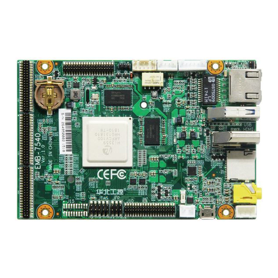
EMB-7540 V1.0 Chapter 1 Product Introduction 1.1 Hardware Specification Size ●Platform:HiSilicon ARM platform ●Size:120mmX80mm Processor ●CPU : Adopts HiSilicon Hi3559A 2*A73+3*A53+1*M7+2*G71+4*DSP+2*NNIE multi-core heterogeneous processors System Memory ●On board: 4GB DDR4 Display ●1xHDMI port Storage ●Provides 1xTF card slot,up to 64G ●On board 16GB iNAND Flash... - Page 9 EMB-7540 V1.0 ●CMOS Sensor: (Design adapter board according to lens specifications),1x 8K30fps input, Or 2x 4K60fps input, Or 4x4K30fps input ,Or 8x1080P30fps input,(with ACP-250 adapter board,up to 4*4Kx4K input) ●USB:Provides 1x Mini USB2.0 (Micro USB),1xUSB3.0 (TYPE A) Expansion Port: ●Provides 2x DI,1x DO(Relay control output);...
-
Page 10: Chapter 2 Hardware Function
Chapter Hardware Function... - Page 11 2.2 Installation Please refer to following steps to assemble your computer: 1.Adjust all jumpers on board EMB-7540 V1.0 according to the user manual. 2.Install other expansion card. 3.Connect all signal line, cable, ,panel control circuit, and power supplier.
-
Page 12: Interfaces Specification
EMB-7540 V1.0 1.Hold the board by edges and don’t touch any components, plugs or socket pins. 2.Wear anti-static gloves/wrist strap while touching the integrated circuit components, such as CPU, RAM, etc. 3.Put those unused or uninstalled components in static shielding bags or trays. - Page 13 EMB-7540 V1.0 UART0 UART0: Signal Name COM0_TX COM0_RX J17: Signal Name Signal Name COM3_TXD COM3_RXD COM4_485+ IO_IN1 COM4_485- IO_IN2...
-
Page 14: Usb Port(Usb,Otg)
EMB-7540 V1.0 2.4.2 USB Port(USB,OTG) Provides 1x Mini USB2.0 (MICRO USB) port,1x USB3.0 (TYPE A) port. Micro USB USB: Standard USB3.0 TYPE A interface definition. 2.4.3 Ethernet interface(LAN) Provides 1x RJ45 network interface ,the yellow one indicates data transmission status,... -
Page 15: Headphone Jack(Mic1
EMB-7540 V1.0 RJ45 LAN LED Status Description: status Function Function ACTLED (Yellow) LILED(Green)Status 100/1000M link FLASH Data transmission 10M link or closed Data stopped 2.4.4 Headphone Jack(MIC1) Support 2xMIC IN,1xheadpone output,provide 1x four-section headphone jack and 1x single MIC IN connector. - Page 16 EMB-7540 V1.0 MIC1 HP: International standard interface definition for standard four-section headphones MIC1: Signal Name MIC1_R MIC1_L...
-
Page 17: Reset
EMB-7540 V1.0 2.4.5 RESET RESET 2.4.6 Display Port HDMI 1xHDMI Display Interface... - Page 18 EMB-7540 V1.0 HDMI...
- Page 19 EMB-7540 V1.0 HDMI: Signal Name Signal Name D2 Shield D1 Shield D0 Shield CK Shield CE Remote DDC DATA DDC CLK HP DET SHELL0 SHELL1 SHELL2 SHELL3 SHELL4 SHELL5 SHELL6 SHELL7 SHELL8 SHELL9 SHELL10 SHELL11 J8: OUTPUT FOR AI Control...
- Page 20 EMB-7540 V1.0 LSB2L LSRST LSDET VCC4 VCC4 J16:Touch Control Signal Name GND- 3.3V TP_INT/GPIO16_7 TP_I2C10_SCL TP_I2C10_SDA TP_RST/GPIO16_4 Signal Name Signal Name 管脚 UART1_RXD/CAN1_RXD_1V8 SDIO2_CDATA1 UART1_TXD/CAN1_TXD_1V8 SDIO2_CDATA2 UART2_RXD/UART1_RTSN SDIO2_CDATA0 UART2_TXD/UART1_CTSN SDIO2_CCLK_OUT SHUB_I2C0_SCL SDIO2_CCMD SHUB_I2C0_SDA SDIO2_CDATA3 SHUB_SPI1_SDO SHUB_SPI1_SCLK SHUB_I2C1_SDA SHUB_SPI1_CSN SHUB_I2C1_SDA SHUB_SPI1_SDI...
- Page 21 EMB-7540 V1.0 WL_REG_ON SHUB_UART0_TXD HOST_WAKEUP_BT PWR_EN1 SHUB_SPI0_SDO PWR_EN2 SHUB_SPI0_SDI PWR_EN0 SHUB_SPI0_SCLK PWR_WAKEUP2 SHUB_SPI0_CSN PWR_WAKEUP1 1V8_SHUB PWR_WAKEUP0 1V8_SHUB PWR_WAKEUP0 3V3_PER J10: Signal Name Signal Name SHUB_PWM_OUT1 DSI_D0P DSI_D0N SPI4_CSN0 SPI4_MISO DSI_D1P SPI4_MOSI/I2C8_SDA DSI_D1N SPI4_SCLK/I2C8_SCL LCD_RESET DSI_CKP LCD_DATA7 DSI_CKN LCD_CLK LCD_DATA1 DSI_D2P...
-
Page 22: Ports(Tf
EMB-7540 V1.0 LCD_DATA4 1V8_PER LCD_DATA3 1V8_PER LCD_DATA2 3V3_PER LCD_VSYNC 3V3_PER J15: Signal Name Signal Name 管脚 3.3V 3.3V PCIE_RXM0 PCIE_RXP0 PCIE_RSTN_3V3 PCIE_CLK_REQ_N PCIE_TXM0 PCIE_TXP0 GPIO12_5 PCIE_REFCLKM PCIE_REFCLKP J12~J14:Expand cmos sensor pin,support 8xMIPI input. 2.4.7 Ports(TF) 1x TF card port. - Page 23 EMB-7540 V1.0 TF card port 2.4.8 Power Port( ) On board 1x2 Pin connector power input port.
- Page 24 EMB-7540 V1.0 PWR: Signal Name +12V 2.4.9 Front Panel Port(JFP) JFP connects power button and indicator on the front panel.
- Page 25 EMB-7540 V1.0 JFP: Signal Name Signal Name PWR_BUTTON0 UPDATE_MODE_N LSADC0_CH0 FUNCTION BOOT_SEL2:UPDATE_MODE_N ENABLE UPDATE FROM SDIO0 DISABLE UPDATE FROM SDIO0...
-
Page 26: Chapter 3 Software Function
EMB-7540 V1.0 Chapter Three Software Function... -
Page 27: Linux 4.9.37 System
EMB-7540 V1.0 Chapter Three Software Function 3.1 Linux 4.9.37 system 3.1.1 mpp sample introduction Detailed usage of these samples can be found on the company's wiki website. If no special instructions are given, all the following commands are entered in the serial terminal. (wiki URL:... -
Page 28: Hdmi
EMB-7540 V1.0 3.1.1.22 vo_wbc_dump Sample of the output image data dump of the write-back device. 3.1.1.23 vpss_chn_dump Sample of users acquire Cnt frames from channels to complete image dump. 3.1.1.24 vpss_src_dump Sample of dump video buffer pool frame data. 3.1.2 HDMI Support HDMI output Instructions:Connect motherboard to 4K display with HDMI line,... -
Page 29: Relay
EMB-7540 V1.0 speed SD card at address 0001 prompts at the terminal. After startup, mount by command: : mount -t vfat /dev/mmcblk1p1 /tmp/ , below the / tmp directory is the contents of the TF card. 3.1.7 Relay Support relay control. -
Page 30: Camera
EMB-7540 V1.0 Running ./sample_audio sample: ./sample_audio 1 voice recording,At this point, the speech will generate audio_chn0.aac file in the current directory and save, Run./sample_audio 2 for sound playback, play the stored audio file. 3.2.11 Camera Supports four sensor interfaces of Sony IMX series. -
Page 31: Appendix
Appendix... -
Page 32: Appendix 1: Glossary
EMB-7540 V1.0 Appendix Appendix 1: Glossary ACPI Advanced Configuration and Power Management. ACPI specifications allow operating system to control most power of the computer and its add-ons. Windows 98/98SE,Windows 2000 and Windows ME supports this specification. BIOS Basic input/output system. It is software including all in/out control code interface in PC. - Page 33 EMB-7540 V1.0 Cluster Communication Port. A universal serial communication interface, usually adopts normative DB 9 connector. DIMM Dual-Inline-Memory-Modules. It is a small circuit board with memory chipset providing 64 bit memory bus width. DRAM Dynamic Random Access Memory. It’s a general type of memory for regular computer which usually store 1 bit with a transistor and a capacitance.
- Page 34 EMB-7540 V1.0 connected directly and function well. PS/2 A keyboard & mouse connective interface specification developed by IBM.PS/2 is a DIN interface with only 6PIN; it also can connect other devices, like modem. It is the Universal Serial Bus for short. A hardware interface adapts to low speed peripherals, and is always used to connect keyboard, mouse etc.
Need help?
Do you have a question about the EMB-7540 and is the answer not in the manual?
Questions and answers