Table of Contents
Advertisement
Quick Links
Advertisement
Table of Contents

Related Manuals for Norco BPC-7934


Summary of Contents for Norco BPC-7934
- Page 1 BPC-7934 Mini-ITX Motherboard User's Manual V1.2...
- Page 2 Before buying products, please learn about the product performance from the distributors to see if it is in line with your needs. NORCO is a registered trademark of Shenzhen NORCO Intelligent Technology CO., LTD.
-
Page 3: Safety Instructions
Safety Instructions 1. Before using this product, please read this user’s manual carefully; 2. Any plate cards not ready to be installed shall be kept in the anti-static protective bags; 3. Before taking out the plate cards from the anti-static protective bags, first place hands on the grounding metal object for a while so as to release the static electricity from your body and hands;... -
Page 4: Table Of Contents
Content Chapter 1 Product Introduction......................1 1.1 Introduction..........................1 1.2 Product Specification........................ 1 Chapter 2 Installation Specification.......................4 2.1 Interface Location and Dimension Diagram................4 2.2 Installation Steps........................5 2.3 Memory Installation........................5 2.4 Jumper Setting...........................5 2.4.1 CMOS Content Clearance /Keep Settings(JCC)..........5 2.4.2 Hardware Switch for System Auto Boot upon Power On(JAT)......7 2.4.3 COM2 Jumper Setting(J5,J6,J8).............. - Page 5 Chapter 3 BIOS Set up......................... 27 AMI BIOS Refresh......................... 27 AMI BIOS Description........................27 BIOS Parameter Setting:......................27 3.1 Main Menu..........................28 3.2 Advanced Menu........................28 3.2.1 ACPI Settings....................... 29 3.2.2 APM Configuration......................30 3.2.3 CPU Configuration......................31 3.2.4 SATA Configuration.....................32 3.2.5 USB Configuration...................... 34 3.2.6 Supper IO Configuration....................
- Page 6 Chapter Product Introdu ction...
-
Page 7: Chapter 1 Product Introduction
Chapter One Product Introduction 1.1 Introduction BPC-7934 is Mini-ITX motherboard, with Intel®NM10 chipset, Intel Cedarview CPU D2550 1.86GHz processor. 1x standard 7Pin SATA port,2x Gigabit Ethernet interface,provide VGA, LVDS, HDMI display port,and 6 x standard DB9 serial port,6xUSB 2.0 ports, can be used for data communication. - Page 8 BPC-7934 Mini-ITX Motherboard Based on Intel Cedar Trail Platform System Memory ●On board memory,support DDR3-800/1066 up to 2G Bytes Storage ●1x standard 7 Pin SATA port LAN Function ●Network controller:With RTL8111F-CGL network chip ●2 x standard RJ45 port ● Support Wake On LAN(WOL)...
- Page 9 BPC-7934 Mini-ITX Motherboard Based on Intel Cedar Trail Platform Expansion Port ●2x MINI PCIe slot, in which 1x MINIPCIE slot support Mini-PCIE WLAN /MSATA optional ●1x SIM card slot;Support 3G module ●1x LPC bus expansion interface (optional) ●1x front panel interface Power Supply ●DC +12V single power supply...
- Page 10 Chapter Install ation Specifi cation...
-
Page 11: Chapter 2 Installation Specification
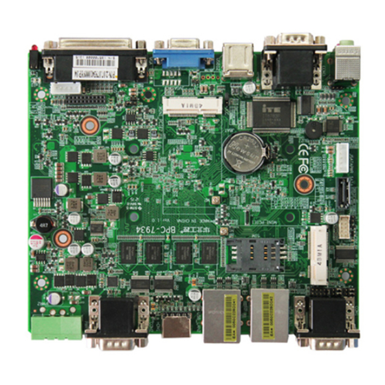
Mini-ITX Motherboard Based on Intel Cedar Trail Platform Chapter 2 Installation Specification 2.1 Interfaces Location and Dimension Following picture illustrates the front interfaces and dimension of board BPC-7934. Please pay attention to the installation process. Improper installation of some components may lead to system failure. -
Page 12: Installation Steps
Mini-ITX Motherboard Based on Intel Cedar Trail Platform 2.2 Installation Steps Please follow the steps below to assemble your computer: 1.Adjust all jumpers onboard BPC-7934 according to the user manual. 2.Install memory; 3.Install other expansion cards. 4.Connect all signal line, cables, panel control circuit and power adapter. - Page 13 BPC-7934 Mini-ITX Motherboard Based on Intel Cedar Trail Platform elimination of previous system settings and make the system back to the original settings (factory default). Steps: (1)Shut down the computer and disconnect power supply; (2)Make the jumper JCC Pin1 and Pin 2 short for 5~10 seconds(Pin1-2)and then make it back to default setting with Pin 2-3 connected;...
-
Page 14: Hardware Switch For System Auto Boot Upon Power On(Jat
BPC-7934 Mini-ITX Motherboard Based on Intel Cedar Trail Platform 2.4.2 Hardware Switch for System Auto Boot upon Power On(JAT) JAT: Setting Open Disable Auto Boot Close Enable Auto Boot 2.4.3 COM2 Jumper Setting(J5,J6,J8) J5,J6,J8 jumper are used to set the transmission mode of COM2,COM2 support RS 232/RS 422/RS 485 transmission mode,... -
Page 15: Lcd Rated Voltage Selection Jumper(Jp1,Jp2
BPC-7934 Mini-ITX Motherboard Based on Intel Cedar Trail Platform J5、J6、J8: COM2 RS232( default ) COM2 RS422 COM2 RS485 1-3 2-4 3-5 4-6 3-5 4-6 1-3 2-4 3-5 4-6 3-5 4-6 5-6 7-8 2.4.4 LCD Rated Voltage Selection Jumper(JP1,JP2) Before using LCD, please know its required working rated voltage. Here jumper sets the... -
Page 16: Interface Specification
BPC-7934 Mini-ITX Motherboard Based on Intel Cedar Trail Platform Setting 3.3V × × × 2.5 Interface Specification When connecting external connectors, please read this manual carefully in order to avoid damage to the motherboard! 2.5.1 SATA Port Board with 1xSATA port... -
Page 17: Serial Port(Com1-Com6
BPC-7934 Mini-ITX Motherboard Based on Intel Cedar Trail Platform SATA SATA: Signal Name 2.5.2 Serial Port(COM1-COM6) Board with 6x standard DB9 port,provide ESD protection COM1/2/3/4/5/6 all support RS232 transmission mode , COM2 also support RS422/485 transmission mode,user can choose by setting the jumper. - Page 18 BPC-7934 Mini-ITX Motherboard Based on Intel Cedar Trail Platform COM2 COM1 COM4 COM3 COM6 COM5 COM1-COM6: Signal Name HDCD# HSIN HSOUT HDTR# HDSR HRTS HCTS...
-
Page 19: Display Port(Vga,Jvga,Lvds,Hdmi
BPC-7934 Mini-ITX Motherboard Based on Intel Cedar Trail Platform 2.5.3 Display Port(VGA,JVGA,LVDS,HDMI) HDMI JVGA LVDS VGA: Signal Name Signal Name Signal Name VGA_R_R VGA_G_R CRT_DDC_DAT_OUT VGA_B_R CRT_HSYNC1 CRT_VSYNC1 VGA_PIN10 CRT_DDC_CLK_OUT JVGA: Signal Name Signal Name VGA_R_R VGA_G_R CRT_DDC_DAT_OUT VGA_B_R CRT_HSYNC1... - Page 20 BPC-7934 Mini-ITX Motherboard Based on Intel Cedar Trail Platform LVDS: Signal Name Signal Name LVDS_VCC_IN LVDS_VIN_12V LVDS_CLK_DN_R LVDS_TX3_DN_R LVDS_TX2_DN_R LVDS_TX1_DN_R LVDS_TX0_DN_R L_BKLTCTL L_BKLTEN LVDS_CLK_DP_R LVDS_TX3_DP_R LVDS_TX2_DP_R LVDS_TX1_DP_R LVDS_TX0_DP_R VDD_PANEL VDD_PANEL Note 1: Pin 2 (LVDS_VIN_12V) output 12V and Pin 1 (LVDS_VCC_IN) output 5V,can be used for LCD backlight;...
-
Page 21: Usb Port(Usb_Lan1,Usb_Lan2,Usb12
BPC-7934 Mini-ITX Motherboard Based on Intel Cedar Trail Platform 2.5.4 USB Port(USB_LAN1,USB_LAN2,USB12) Provide 6x standard USB port,support USB2.0. USB_LAN2 USB_LAN1 USB12 USB_LAN1: Signal Name Signal Name VCC_USB34 USBD_N3 USBD_P3 VCC_USB34 USBD_N4 USBD_P4... -
Page 22: Ethernet Interface(Lan1,Lan2
BPC-7934 Mini-ITX Motherboard Based on Intel Cedar Trail Platform USB_LAN2: Signal Name Signal Name VCC_USB34 USBD_T5N USBD_T5P VCC_USB34 USBD_T6P USBD_T6N USB12: Signal Name Signal Name VCC_USB12 VCC_USB12 USBD_ N2 USBD_ N1 USBD_ P2 USBD_ P1 2.5.5 Ethernet Interface(LAN1,LAN2) Provide 2x Gigabit network interface... - Page 23 BPC-7934 Mini-ITX Motherboard Based on Intel Cedar Trail Platform Definition of POE option J15 for LAN1: Signal Name MDI0+ MDI0- MDI1+ MDI1- MDI2+ MDI2- MDI3+ MDI3- Definition of POE option J13 for LAN2: Signal Name MDI0+ MDI0- MDI1+ MDI1- MDI2+...
- Page 24 BPC-7934 Mini-ITX Motherboard Based on Intel Cedar Trail Platform JGPIO KBMS JGPIO KBMS: Signal Name Signal Name VCC5_KBMS MS_CLK_R MS_DATA_R KB_DATA_R KB_CLK_R VCC5_KBMS IO_00 IO_01 IO_04 IO_02 IO_05 IO_03 IO_06 IO_07 FP_RESET_BT POWERSW#_R...
-
Page 25: Power Interface(Pwr1
BPC-7934 Mini-ITX Motherboard Based on Intel Cedar Trail Platform 2.5.7 Power Interface(PWR1) PWR1 PWR1: Signal Name +12V... -
Page 26: Sata Power Supply Voltage(Jsatapwr
BPC-7934 Mini-ITX Motherboard Based on Intel Cedar Trail Platform 2.5.8 SATA Power Supply Voltage(JSATAPWR) JSATAPWR JSATAPWR: Signal Name +3.3V +12V 2.5.9 Fan Interface(CPU_FAN) Board with 1x 4Pin CPU fan interface When using the fan, make sure that the fan wiring is... -
Page 27: Audio Port(Audio、Line_In
BPC-7934 Mini-ITX Motherboard Based on Intel Cedar Trail Platform CPU_FAN CPU”_FAN: Signal Name +12V FANIN FANOUT 2.5.10 Audio Port(Audio、LINE_in) Provide 1x Audio port,Green for Line-out. Provide 1x Line-in. - Page 28 BPC-7934 Mini-ITX Motherboard Based on Intel Cedar Trail Platform LINE_in Audio LINE_in: Signal Name LINE1_L LINE1_R...
-
Page 29: Lvds Power Supply Voltage(Jlvds Pwr
BPC-7934 Mini-ITX Motherboard Based on Intel Cedar Trail Platform 2.5.11 LVDS Power Supply Voltage(JLVDS PWR) JLVDS PWR JLVDS PWR Signal Name BKLT_CTRT BKLT_EN +12V 2.5.12 Front Panel Interface(JFP) Front panel pins for connecting to the function buttons and indicators set on the front panel... - Page 30 BPC-7934 Mini-ITX Motherboard Based on Intel Cedar Trail Platform JFP: Signal Name Signal Name PLED+ HDD_LED+ HDD_LED- BUZZDATA# FP_RESET_BT POWERSW#_R Please follow the table below to connect, pay attention to the anode (+) and cathode (-), otherwise some function cannot be realized.
- Page 31 BPC-7934 Mini-ITX Motherboard Based on Intel Cedar Trail Platform power on, power LED is on;When system is power off, power LED is off. 2)HD Status LED Pins(Pin 3、Pin 4 HDD LED) Generally, there is 1x HD device operation status indicator on the enclosure panel, which will flash when HD device is reading and writing.
-
Page 32: Mouse Keyboard Interface(Kbms
BPC-7934 Mini-ITX Motherboard Based on Intel Cedar Trail Platform MINI_PCIE1 MINI_PCIE2 J3: Signal Name WWAN2_WIFI_LED# 3.3VSB J4: Signal Name WWAN1_WIFI_LED# 3.3VSB 2.6 ACP-315 Interface Specification 2.6.1 Mouse Keyboard Interface(KBMS) Provide 1x standard PS/2 mouse keyboard interface. -
Page 33: Power Interface(Pwrbt、Rstbt、Swbt
BPC-7934 Mini-ITX Motherboard Based on Intel Cedar Trail Platform KBMS MS: Signal Name MS_DAT A MS_CLK KB: Signal Name KB_DATA KB_CLK 2.6.2 Power Interface( PWRBT、RSTBT、SWBT ) Board with 1x RSTBT reset key, 1x SWBT one key Ghost and 1x PWRBT power switch. -
Page 34: Chapter 3 Bios Set Up
Chapter Three BIOS Set up... -
Page 35: Ami Bios Refresh
BPC-7934 Mini-ITX Motherboard Based on Intel Cedar Trail Platform Chapter Three BIOS Set up AMI BIOS Refresh BIOS functions as a bridge connecting hardware and operating system. Hardware and software are upgrading all the time, so when your system goes wrong, for example, your system cannot support the newest CPU, you need to upgrade BIOS to keep up with the latest technology. -
Page 36: Main Menu
BPC-7934 Mini-ITX Motherboard Based on Intel Cedar Trail Platform automatically turn to the setup setting screen after detection of IDE and other devices. 1、Power on or restart the system, self-detection message will display on the screen. 2 、 When the prompt “Press <Del> to enter setup, press < Del > to enter the BIOS setup program. -
Page 37: Advanced Menu
BPC-7934 Mini-ITX Motherboard Based on Intel Cedar Trail Platform System Date System Date Format: Month (Jan.-Dec.) , Date (01-31) , Year (up to 2099) , Week (Mon.~Sun.) System Time System Time Format::Hour/(00-23),Minute/(00-59),Second/(00-59) 3.2 Advanced Menu Reminder: the wrong parameter value setting in the following parts may cause your system... -
Page 38: Acpi Settings
BPC-7934 Mini-ITX Motherboard Based on Intel Cedar Trail Platform CPU configuration and common setting SATA Configuration Hard disk mode settings and hard disk information USB Configuration USB information and control option Super IO Configuration Super IO configuration information, including COM port interrupt number and address... -
Page 39: Apm Configuration
BPC-7934 Mini-ITX Motherboard Based on Intel Cedar Trail Platform 3.2.2 APM Configuration RTC Power on Function Automatic power up setting,set value: [Enabled] [Disabled] ;Default: [Disabled]. When this option is set to Enabled, the following two options will appear to set the specific wake-up... -
Page 40: Cpu Configuration
BPC-7934 Mini-ITX Motherboard Based on Intel Cedar Trail Platform 3.2.3 CPU Configuration Read-only items contain CPU details, including CPU manufacturers, models, frequencies, L1 cache size, L2 cache size and other information. Hyper-Threading Whether to use the hyper threading technology of CPU, setting value: [Enabled][Disabled] Execute Disabled Bit “... -
Page 41: Sata Configuration
BPC-7934 Mini-ITX Motherboard Based on Intel Cedar Trail Platform EIST Intelligent frequency reduction technology ON or OFF settings CPU C State Report Whether to Enable CPU power state report,set value:[Disabled],[Enabled]. 3.2.4 SATA Configuration Serial-ATA Controller(S) [Disabled] / [Enabled] SATA controller... -
Page 42: Usb Configuration
BPC-7934 Mini-ITX Motherboard Based on Intel Cedar Trail Platform 3.2.5 USB Configuration USB function [Disabled] / [Enabled] USB port USB 2.0 (EHCI) Support [Enabled]: Allow using USB EHCI transport protocol, transmission rate up to 480Mpbs [Disabled]:USB2.0 port is forbidden,the traditional transmission rate is 12Mpbs Legacy USB Support Legacy USB supports setting. -
Page 43: Supper Io Configuration
BPC-7934 Mini-ITX Motherboard Based on Intel Cedar Trail Platform 3.2.6 Supper IO Configuration Serial Port 1 Configuration 1)Serial Port [Enabled] / [Disabled] serial port 2)Device Setting(read only) Display the interrupt and address of the serial port 3)Change Setting This item is used to change the serial port setting. It is recommended to select Auto by default Below setting of Serial Port 1-6 Configuration are the same as above. - Page 44 BPC-7934 Mini-ITX Motherboard Based on Intel Cedar Trail Platform...
- Page 45 BPC-7934 Mini-ITX Motherboard Based on Intel Cedar Trail Platform...
- Page 46 BPC-7934 Mini-ITX Motherboard Based on Intel Cedar Trail Platform...
-
Page 47: H/W Monitor
BPC-7934 Mini-ITX Motherboard Based on Intel Cedar Trail Platform 3.2.7 H/W Monitor PC Health Status Hardware security detection, BIOS will display the current system temperature, CPU temperature, fan speed, and other related voltage values. All of the above parameters have a certain range, and the system cannot operate beyond these ranges. -
Page 48: Chipset Menu
BPC-7934 Mini-ITX Motherboard Based on Intel Cedar Trail Platform 3.3 Chipset Menu North Bridge North bridge configuration options. Including display memory, display device and other options South Bridge South bridge configuration options. Including sound card, network card, auto boot upon... -
Page 49: North Bridge
BPC-7934 Mini-ITX Motherboard Based on Intel Cedar Trail Platform 3.3.1 North Bridge Boot Display Device To set the display device used to display the output when the system starts Flat Panel Type Sets the resolution when LVDS display mode is selected... -
Page 50: South Bridge
BPC-7934 Mini-ITX Motherboard Based on Intel Cedar Trail Platform 3.3.2 South Bridge Audio Controller Enabled / Disabled on board sound card LAN 1/2 Controller Enabled / Disabled onboard LAN controller Restore AC Power Loss This option is to setup the system status while connecting the power again after the AC Power Loss <Power Off>: System remains the status of power off. -
Page 51: Boot Menu
BPC-7934 Mini-ITX Motherboard Based on Intel Cedar Trail Platform 3.4 Boot Menu Setup Prompt Timeout Number of seconds to wait for setup shortcut key. If don’t press Setup key within the pre-set time, system will continue to start. Boot up Numlock State This function allows users to activate Numlock function when boot up. -
Page 52: Security Menu
BPC-7934 Mini-ITX Motherboard Based on Intel Cedar Trail Platform Hard Drive BBS Priorities This option contains HDD that can be used as boot device. If multiple HDDs in this option, priority should set for these HDDs, then the prior one will show in Boot Option #1 3.5 Security Menu... -
Page 53: Save & Exit Menu
BPC-7934 Mini-ITX Motherboard Based on Intel Cedar Trail Platform 3.6 Save & Exit Menu Load Defaults Whether to restore the BIOS default settings. Save Change and Exit To save changes to BIOS settings and restart the computer. Press Enter on this item to confirm. -
Page 54: Appendix
Appendix... -
Page 55: Appendix 1:Watchdog Programming Guide
BPC-7934 Mini-ITX Motherboard Based on Intel Cedar Trail Platform Appendix Appendix 1:Watchdog Programming Guide Watchdog reference code(ASM) -------------------------------------------------------------------------------------------------------------- We can operate ports to operate watchdogs. Different functions of Watchdog Timer can be realized by manipulating ports by writing data to the corresponding ports. - Page 56 BPC-7934 Mini-ITX Motherboard Based on Intel Cedar Trail Platform temp |= 0x02; outportb(datap,temp); //lock...
-
Page 57: Appendix 2:Glossary
BPC-7934 Mini-ITX Motherboard Based on Intel Cedar Trail Platform Appendix 2:Glossary ACPI Advanced Configuration and Power Management. ACPI specifications allow operating system to control most power of the computer and its add-on. BIOS Basic input/output system. It is software including all in/out control code interface in PC. The software will detect hardware when it auto boot, operate OS, and provide an interface between OS and hardware. - Page 58 BPC-7934 Mini-ITX Motherboard Based on Intel Cedar Trail Platform DRAM Dynamic Random Access Memory. It’s a general type of memory for regular computer which usually store 1 bit with a transistor and a capacitance. With the development of the technology, more and more types of DRAM with different specifications exist in computer applications.
- Page 59 BPC-7934 Mini-ITX Motherboard Based on Intel Cedar Trail Platform interface with only 6PIN; it also can connect other devices, like modem. It is the Universal Serial Bus for short. A hardware interface adapts to low speed peripherals, and is always used to connect keyboard, mouse etc. One PC can connect maximum 127 USB...
Need help?
Do you have a question about the BPC-7934 and is the answer not in the manual?
Questions and answers