Keithley 2700 User Manual
Multimeter/switch system
Hide thumbs
Also See for 2700:
- Service manual (174 pages) ,
- User manual (500 pages) ,
- Quick start manual (52 pages)

Related Manuals for Keithley 2700


Summary of Contents for Keithley 2700
- Page 1 Test Equipment Depot - 800.517.8431 - 99 Washington Street Melrose, MA 02176 - TestEquipmentDepot.com Model 2700 Multimeter/Switch System User’s Manual A G R E A T E R M E A S U R E O F C O N F I D E N C E...
- Page 2 WARRANTY Keithley Instruments, Inc. warrants this product to be free from defects in material and workmanship for a period of 3 years from date of shipment. Keithley Instruments, Inc. warrants the following items for 90 days from the date of shipment: probes, cables, rechargeable batteries, diskettes, and documentation.
- Page 4 Model 2700 Multimeter/Switch System User’s Manual ©2001, Keithley Instruments, Inc. All rights reserved. Cleveland, Ohio, U.S.A. Sixth Printing, November 2002 Document Number: 2700-900-01 Rev. F...
- Page 5 Revision D (Document Number 2700-900-01) ..............July 2001 Revision E (Document Number 2700-900-01) ............November 2001 Revision F (Document Number 2700-900-01)............November 2002 All Keithley product names are trademarks or registered trademarks of Keithley Instruments, Inc. Other brand names are trademarks or registered trademarks of their respective holders.
- Page 6 Keithley products are designed for use with electrical signals that are rated Installation Category I and Installation Category II, as described in the International Electrotechnical Commission (IEC) Standard IEC 60664. Most measurement, control, and data I/O signals are Installation Category I and must not be directly connected to mains voltage or to voltage sources with high tran- sient over-voltages.
- Page 7 To maintain protection from electric shock and fire, replacement components in mains circuits, including the power transformer, test leads, and input jacks, must be purchased from Keithley Instruments. Standard fuses, with applicable national safety ap- provals, may be used if the rating and type are the same. Other components that are not safety related may be purchased from other suppliers as long as they are equivalent to the original component.
-
Page 8: Table Of Contents
Connector and adapter kits for switching modules ..Cables and adapters (GPIB and trigger link) ....Rack mount kits ............Carrying case ............... Model 2700 features ..............Plug-in switching modules ............Pseudocards ................. Identifying installed switching modules ......Front and rear panel familiarization ........... - Page 9 Remote programming information ........... 1-25 Quick start exercises ..............1-25 Basic DMM measurements — front panel inputs ..... 1-26 Exercise 1 — Basic DMM measurements ....1-27 Closing and opening channels — system channel operation ............1-28 Close/open operation ..........1-29 Exercise 2 —...
- Page 10 Identifying installed modules and viewing closed channels ..2-25 CARD menu ..............2-25 Switching module queries (remote operation) ....2-27 *OPT? ................ 2-27 ROUTe:CLOSe? ............2-28 ROUTe:MULTiple:CLOSe? ........2-28 ROUTe:MULTiple:CLOSe:STATe? <clist> ....2-28 SYSTem:CARD commands ........2-28 Relay closure count ..............2-29 Reading relay closure count ..........
- Page 11 Resistance measurements (Ω2 and Ω4) ........3-16 Connections ............... 3-17 Front panel inputs ............3-17 Model 7700 switching module ........3-18 Shielding ..............3-19 Cable leakage ............. 3-19 Standard resistance measurements ........3-19 Offset-compensated ohms ..........3-20 Enabling/disabling offset-compensated ohms .... 3-21 Performing offset-compensated ohms measurements ............
- Page 12 Remote programming for basic measurements ......3-38 Basic measurement commands ......... 3-38 Basic measurement programming examples ....3-44 Example #1 — continuous triggering ......3-44 Example #2 — one-shot triggering ......3-44 Example #3 — temperature measurement using Model 7700 ........... 3-44 Example #4 —...
- Page 13 Remote programming — range ........... Range commands ............Range programming examples ........Digits ..................Scanning ................Remote programming — digits ........... Digits commands ............Digits programming examples ........Rate and bandwidth ..............Rate ..................Bandwidth ................Scanning ................Remote programming — rate and bandwidth ....4-10 Rate and bandwidth commands .........
- Page 14 Ratio and channel average ............5-15 Basic operation ..............5-16 Scanning ..............5-17 Remote programming — ratio and channel average ..5-18 Ratio and channel average commands ....... 5-18 Ratio and channel average programming examples .. 5-19 dB ..................... 5-19 dB configuration ............
- Page 15 Saving the configured scan ......... 7-12 Scan reset ................7-13 Simple scan ............... 7-14 Advanced scan ..............7-15 Advanced scan setup notes ......... 7-15 Advanced scan setup procedure ......... 7-16 Setting delay ..............7-18 Monitor channel ..............7-18 Auto channel configuration ..........7-19 Saving setup ..............
- Page 16 External triggering example ..........Model 2700 ..............8-10 Model 7002 ..............8-10 External triggering with BNC connections ....... 8-12 Remote programming — triggering ......... 8-13 Trigger model (remote operation) ........8-13 Idle and initiate ............8-13 Trigger model operation ............
- Page 17 GPIB standards ..............10-4 Selecting GPIB and setting primary address ..... 10-4 GPIB connections .............. 10-5 General bus commands ............. 10-8 REN (remote enable) ............10-8 IFC (interface clear) ............10-8 LLO (local lockout) ............10-9 GTL (go to local) ............... 10-9 DCL (device clear) ............
- Page 18 RS-232 interface operation ............ 10-18 Sending and receiving data ..........10-18 Baud rate ................. 10-18 Signal handshaking (flow control) ........10-19 Terminator ............... 10-19 Selecting and configuring RS-232 interface ....10-20 RS-232 connections ............10-21 Error messages ..............10-22 Status Structure Overview ..................
- Page 19 Common Commands Description ..............12-3 Description ..............12-4 Description ..............12-6 SCPI Signal Oriented Measurement Commands CONFigure:<function> [<rang>], [<res>], [<clist>] ....13-3 FETCh? ..................13-5 READ? ..................13-6 MEASure:<function>? [<rang>], [<res>], [<clist>] ....13-7 FORMat and Miscellaneous SYSTem Commands FORMat commands ..............14-2 FORMat[:DATA] <type>[,<length>] .......
- Page 20 Model 7700 Connection Guide Card configuration — schematic ..........Connections and wiring ............Screw terminals ..............Wiring procedure ............... Typical connections ............Connection log ..............B-10 Status and Error Messages Signal Processing Sequence and Data Flow Signal processing sequence ............Basic signal processing ............
- Page 21 Continuous measurement mode ........D-12 Scanning ................D-13 Measurement Considerations Measurement considerations ............. Thermoelectric potentials ........... Thermoelectric coefficients ......... Thermoelectric generation ..........Minimizing thermal EMFs ..........Nulling residual thermal offsets ........Source resistance noise ............Johnson noise equation ..........Minimizing source resistance noise ......Magnetic fields ..............
- Page 22 (continuous triggering) ............ 1-37 Closing and Opening Switching Module Channels Figure 2-1 2-wire system channel connections to Model 2700 DMM ..Figure 2-2 4-wire system channel connections to Model 2700 DMM ..Figure 2-3 System channel operation — closing next or previous measurement channel ............
- Page 23 Figure 3-5 DCI and ACI connections using Model 7700 switching module ................3-15 Ω2 and Ω4 connections for front panel inputs ..... Figure 3-6 3-17 Ω2 and Ω4 connections for Model 7700 switching Figure 3-7 module ................3-18 Figure 3-8 Thermocouple connections ..........3-26 Figure 3-9 Thermistor connections ............
- Page 24 IEEE-488 connector location ..........10-7 Figure 10-4 RS-232 interface connector ..........10-21 Status Structure Figure 11-1 Model 2700 status register structure ........11-3 Figure 11-2 16-bit status register ............. 11-5 Figure 11-3 Status byte and service request (SRQ) ......... 11-6 Figure 11-4 Standard event status ............
- Page 25 Signal Processing Sequence and Data Flow Figure D-1 Basic signal processing ............Figure D-2 Signal processing using instrument features ......Figure D-3 Signal processing using Ratio or Channel Average ....Figure D-4 Data flow for remote operation ..........Measurement Considerations Figure E-1 Thermal EMF generation ............
- Page 26 List of Tables Getting Started Table 1-1 Model 77XX series switching modules ......... Table 1-2 Fuse ratings ................1-15 Table 1-3 Display commands ............... 1-17 Table 1-4 Default settings ..............1-21 Table 1-5 Default setup commands ............1-24 Table 1-6 Exercise 1—Measure AC volts - store readings in buffer ..
- Page 27 Buffer Table 6-1 Buffer commands ..............Scanning Table 7-1 Scanning commands ............. 7-28 Table 7-2 External trigger scan example ..........7-34 Table 7-3 Monitor scan example ............7-37 Triggering Table 8-1 Auto delay settings ..............Table 8-2 SCPI commands — triggering ..........8-16 Limits and Digital I/O Table 9-1...
- Page 28 Table F-7 Type S inverse function polynomial ........Table F-6 Type R inverse function polynomial ........Table F-9 Model 2700 curve fitting constants for thermistors ....Table F-8 Type T inverse function polynomial ........Table F-10 RTD parameters ..............IEEE-488 Bus Overview Table G-1 IEEE-488 bus command summary ........
-
Page 30: Getting Started
QS1 • Front and rear panel familiarization — Summarizes the controls and connectors of the instrument. Rack mounting — Covers the options available for rack mounting the Model 2700 • in a standard 19-inch rack. Power-up — Covers line power connection, line voltage setting, fuse replacement, QS2 •... -
Page 31: General Information
General information Warranty information Warranty information is located at the front of this manual. Should your Model 2700 require warranty service, contact the Keithley representative or authorized repair facility in your area for further information. When returning the instrument for repair, be sure to fill out and include the service form at the back of this manual to provide the repair facility with the necessary information. -
Page 32: Inspection
Getting Started Inspection Model 2700 was carefully inspected electrically and mechanically before shipment. After unpacking all items from the shipping carton, check for any obvious signs of physical damage that may have occurred during transit. (There may be a protective film over the display lens, which can be removed). -
Page 33: Connector And Adapter Kits For Switching Modules
Models 7701, 7707, and 7709 switching modules. Cables and adapters (GPIB and trigger link) Models 7007-1 and 7007-2 shielded GPIB cables — Connect Model 2700 to the GPIB bus using shielded cables and connectors to reduce electromagnetic interference (EMI). Model 7007-1 is one meter long; Model 7007-2 is two meters long. -
Page 34: Rack Mount Kits
Model 2700 Multimeter/Switch System User’s Manual Getting Started Rack mount kits Model 4288-1 single fixed rack mount kit — Mounts a single Model 2700 in a standard 19-inch rack. Model 4288-2 side-by-side rack mount kit — Mounts two instruments (Models 182, 428, 486, 487, 2000, 2001, 2002, 2010, 2400, 2410, 2420, 2430, 2700, 6430, 6517A, 7001) side-by-side in a standard 19-inch rack. -
Page 35: Plug-In Switching Modules
The digital trigger link and hardware interlock input can also be accessed at this port. • Monitor — The Model 2700 can monitor a selected channel. A scan can be trig- gered to start when the Monitor detects a reached reading limit. •... -
Page 36: Table 1-1 Model 77Xx Series Switching Modules
1 and totalizer 2 connect to Latching relays hold their open/close state after the Model 2700 is turned off. When turned on, all relays open after a few seconds. All multiplexers can be configured as two independent multiplexers. -
Page 37: Pseudocards
Model 7700, 7701, 7702, 7703, 7705, 7708, or 7709 switching module is removed while the Model 2700 is on, the instrument will operate as if the module is installed. That is, the Model 2700 will operate as if the pseudocard is installed. -
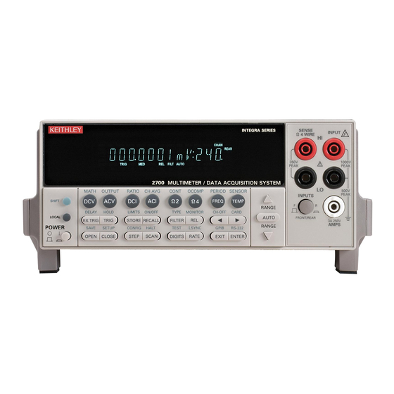
Page 38: Figure 1-1 Model 2700 Front Panel
Use to select a shifted function or operation. LOCAL Cancels GPIB remote mode. POWER Power switch. In position turns 2700 on (I), out position turns it off (O). 2 Function and operation keys: Top Row Unshifted Selects DC voltage measurement function. - Page 39 Restores a default setup (factory or *RST) or a saved setup. Enables/disables buffer auto clear, auto scan, and auto channel configuration. Sets timestamp, date, and time. Displays serial number of Model 2700. CONFIG Selects and configures a simple scan or an advanced scan.
- Page 40 Model 2700 Multimeter/Switch System User’s Manual Getting Started 1-11 4 Display annunciators: * (asterisk) Readings being stored in buffer. ↔ (more) Indicates additional selections are available. ))) (speaker) Beeper on for continuity or limits testing. Digital input/output or analog output active (set to non-default value).
-
Page 41: Rear Panel Summary
figured for line voltages of 100V/120V/220V/240VAC at line frequencies of 50 or 60Hz. 6 Slot 1 and Slot 2 Two slots to accommodate Keithley Model 77XX series switching modules. The Model 2700 is shipped from the factory with slot covers installed. Please note additional slot covers can be requested from Keithley Instruments. -
Page 42: Power-Up
Getting Started 1-13 Power-up Line power connection Follow the procedure below to connect the Model 2700 to line power and turn on the instrument. Check to see that the line voltage indicated in the window of the fuse holder assem- (Figure 1-3) is correct for the operating voltage in your area. -
Page 43: Line Frequency
Fuse Holder Assembly Line frequency The Model 2700 will operate at line frequencies from 45Hz to 66Hz, and 360Hz to 440Hz. There are no user-settings for line frequency. It is automatically sensed at power-up. The following command can be used to read the line frequency: SYSTem:LFRequency? ' Query power line frequency. -
Page 44: Setting Line Voltage And Replacing Fuse
Model 2700 Multimeter/Switch System User’s Manual Getting Started 1-15 Setting line voltage and replacing fuse A rear panel fuse located next to the AC receptacle protects the power line input of the instrument. If the line voltage setting needs to be changed or the line fuse needs to be replaced, perform the following steps. -
Page 45: Power-Up Sequence
Model 2700 Multimeter/Switch System User’s Manual Power-up sequence On power-up, the Model 2700 performs self-tests on its EPROM and RAM and momen- tarily lights all segments and annunciators. If a failure is detected, the instrument momen- tarily displays an error message and the ERR annunciator turns on. (Error messages are... -
Page 46: Remote Programming
Appendix Remote programming — display Using remote programming, the Model 2700 can display a custom ASCII message (up to 12 characters). Also, the front panel display and controls can be disabled. Display commands The commands are listed in Table 1-3. -
Page 47: Display:text:data
1-18 Getting Started Model 2700 Multimeter/Switch System User’s Manual DISPlay:TEXT:DATA <a> Define text message This command defines the text message for display. A message can be as long as 12 char- acters. A space counts as a character. Excess message characters results in an error. The characters must be enclosed in either single quotes (‘... -
Page 48: Defaults And User Setups
1-19 Defaults and user setups Model 2700 can be restored to one of two default setup configurations (FACTory or *RST), or four user-saved (SAV0, SAV1, SAV2, or SAV3). As shipped from the factory, Model 2700 powers up to the factory (FACT) default settings. -
Page 49: Saving And Restoring Setups
If the settings for a user setup or power-on setup do not match the switching module types presently installed in the Model 2700, error +520 (Saved setup scancard mismatch) occurs when the setup is recalled. The scan list will reset to the factory defaults and all channels will open. - Page 50 Model 2700 Multimeter/Switch System User’s Manual Getting Started 1-21 Table 1-4 Default settings Setting Factory *RST Set Diff ✓ Auto channel configuration No (off) No effect Autozero Buffer No effect No effect ✓ Auto clear Yes (on) No effect Channel Average...
-
Page 51: Table 1-4 Default Settings
1-22 Getting Started Model 2700 Multimeter/Switch System User’s Manual Table 1-4 (continued) Default settings Setting Factory *RST Set Diff Limits LO Limit 1 HI Limit 1 LO Limit 2 HI Limit 2 Line Synchronization Math mX+B Scale Factor Offset Units “X”... - Page 52 Model 2700 Multimeter/Switch System User’s Manual Getting Started 1-23 Table 1-4 (continued) Default settings Setting Factory *RST Set Diff RS-232 Baud rate No effect No effect Flow control XonXoFF XonXoFF Terminator No effect No effect Scanning Disabled Disabled ✓ Auto scan...
-
Page 53: Remote Programming - Default And User Setups
Programming example *SAV 2 ' Save present setup in memory location 2. SYST:POS SAV2 ' Specify SAV2 setup as the power-on setup. *RST ' Return 2700 to RST defaults. *RCL 2 ' Return 2700 to setup stored in memory location 2. -
Page 54: Remote Programming Information
(?) that follows the command word. A query command requests (queries) the programmed status of that command. When a query command is sent and Model 2700 is addressed to talk, the response message is sent to the computer. NOTE For complete details, see “Programming syntax,”... -
Page 55: Basic Dmm Measurements - Front Panel Inputs
Section 3 for details on basic DMM operation. The Model 2700 is shipped from the factory to power-up to factory defaults. The instru- ment powers up to a setup that continuously measures DC volts. Some of the default set- tings for the DCV function include auto range enabled, 6½-digit resolution, filter enabled, and slow reading rate. -
Page 56: Exercise 1 - Basic Dmm Measurements
Model 2700 Multimeter/Switch System User’s Manual Getting Started 1-27 Exercise 1 — Basic DMM measurements The exercise in Table 1-6 measures ACV on the 10V range and stores 15 readings in the buffer. Table 1-6 Exercise 1—Measure AC volts - store readings in buffer... -
Page 57: Closing And Opening Channels - System Channel Operation
1-28 Getting Started Model 2700 Multimeter/Switch System User’s Manual Closing and opening channels — system channel operation NOTE Section 2 for details on closing and opening switching module channels. NOTE The following discussion assumes a multiplexing switching module (i.e., Model 7700) is installed in slot 1 of the mainframe. -
Page 58: Close/Open Operation
When a system channel is closed, the channel number will be displayed on the Model 2700. The slot number for the module is also displayed. For example, “103” indicates that system input channel 3 for a module in slot 1 is closed. -
Page 59: Figure 1-6 Front Panel Keys To Close And Open System Channels
1-30 Getting Started Model 2700 Multimeter/Switch System User’s Manual Figure 1-6 Front panel keys to close and open system channels Close next measurement channel Press OPEN key Press CLOSE key OPEN CLOSE OPEN CLOSE Display ALL Display SINGLE option CLOSE:SINGLE... -
Page 60: Exercise 2 - Closing And Opening Channels (System Channel Operation)
Model 2700 Multimeter/Switch System User’s Manual Getting Started 1-31 Exercise 2 — Closing and opening channels (system channel operation) The exercise in Table 1-7 demonstrates a sequence to close and open channels of a Model 7700 installed in slot 1 of the mainframe. -
Page 61: Figure 1-7 Simple Scan Operation
NOTE The Model 2700 can also be configured to run an advanced scan. For an advanced scan, each channel can have its own unique setup (i.e., function, range, etc.). Advanced scanning is covered in... -
Page 62: Exercise 3 - Simple Scanning
Model 2700 Multimeter/Switch System User’s Manual Getting Started 1-33 For remote programming, the following commands are used for simple scanning: ROUTe:SCAN <clist> ' Define scan list*. TRIGger:COUNt <NRf> ' Specify number of scans (1 to 11000 or INFinity). SAMPle:COUNt <NRf>... -
Page 63: Trigger And Return Readings - Remote Programming
1-34 Getting Started Model 2700 Multimeter/Switch System User’s Manual Trigger and return readings — remote programming There are several commands used to trigger and return readings. The proper commands and sequence to use depend on the trigger state (continuous or non-continuous) and what you are trying to accomplish. -
Page 64: Figure 1-8 Exercise 4 — Trigger And Return A Single Reading
Model 2700 Multimeter/Switch System User’s Manual Getting Started 1-35 Figure 1-8 Exercise 4 — Trigger and return a single reading Place 2700 in INIT:CONT OFF non-continuous TRIG:COUN 1 trigger state Trigger Configuration Set 2700 to perform SAMP:COUN 1 one measurement... -
Page 65: Figure 1-9 Exercise 5 - Trigger And Return Multiple Readings
1-36 Getting Started Model 2700 Multimeter/Switch System User’s Manual Figure 1-9 Exercise 5 — Trigger and return multiple readings Clear buffer TRAC:CLE Place 2700 in non-continuous INIT:CONT OFF trigger state TRIG:COUN 1 Trigger Configuration Set 2700 to perform “x” SAMP:COUN x... - Page 66 Model 2700 Multimeter/Switch System User’s Manual Getting Started 1-37 Figure 1-10 Exercise 6 — Return a single reading (continuous triggering) Place 2700 in SAMP:COUN 1 continuous Trigger Configuration INIT:CONT ON trigger state. FETCh? DATA? Return Readings CALC:DATA? DATA:FRESh? 2, 3...
- Page 67 1-38 Getting Started Model 2700 Multimeter/Switch System User’s Manual...
-
Page 68: Closing And Opening Switching Module Channels
• Switching module installation and connections — Explains how to install a switching module (or pseudocard) into the Model 2700 mainframe. Also explains where to find connection information which should only be performed by qualified service personnel. -
Page 69: Close/Open Overview
NOTE The Model 2700 can scan switching module channels. Each channel in the scan can have its own unique setup configuration. Scanning is covered in Section... -
Page 70: Switching Module Installation And Connections
Perform the following steps to install a switching module into the Model 2700 mainframe: Turn the Model 2700 off and disconnect the power line cord and any other cable connected to the rear panel. Position the Model 2700 so you are facing the rear panel. -
Page 71: Connections
• Before making or breaking connections to the switching module, make sure the Model 2700 is turned off and power is removed from all external circuitry. • Do not connect signals that will exceed the maximum specifica- tions of switching module. -
Page 72: Pseudocards
There is a pseudocard for every Keithley Model 77XX series switching module. A pseudocard cannot be installed from the front panel. However, once it is installed you can take the Model 2700 out of remote and use the front panel. Pressing the LOCAL key takes the Model 2700 out of remote. -
Page 73: System Channel Operation
DMM Input of the Model 2700. The system channel number is displayed on the Model 2700. For a 4-wire function (i.e., Ω4), the paired channel for the system channel is internally connected to DMM Sense. The paired channel is not displayed on the Model 2700. -
Page 74: 2-Wire Functions
DMM Input of the Model 2700. Assume a Model 7700 switching module is installed in slot 1 of the mainframe. When channel 101 is closed using the system channel close keys, both the Channel 1 relay and the backplane isolation relay (Channel 25) close to connect the chan- nel to the DMM. -
Page 75: 4-Wire Functions (Paired Channels)
Channel 23 relay closes to isolate channel 1 from channel 11. The complete simplified schematic of Model 7700 is provided in Figure 2-12. Figure 2-2 4-wire system channel connections to Model 2700 DMM Model 2700 Slot 1 Model 7700 Switching Module Channel 1 Relay... -
Page 76: Controlling The System Channel
Model 2700 Multimeter/Switch System User’s Manual Close/Open Switching Module Channels Controlling the system channel When a measurement channel is closed, a previous system channel (and, for a 4-wire func- tion, its paired channel) is first opened. The closed measurement channel becomes the sys- tem channel. -
Page 77: Close Key (Single Menu Option)
2-10 Close/Open Switching Module Channels Model 2700 Multimeter/Switch System User’s Manual CLOSE key (SINGLE menu option) The SINGLE menu option for the CLOSE key can be used to select a measurement chan- nel as the system channel (Figure 2-4). Perform the following steps to select the system channel: Press the CLOSE key. -
Page 78: Open Key (All Menu Option)
Model 2700 Multimeter/Switch System User’s Manual Close/Open Switching Module Channels 2-11 OPEN key (ALL menu option) The ALL menu option of the OPEN key opens all channels for all switching modules installed in the Model 2700 (Figure 2-5). For example, if a Model 7700 switching module... -
Page 79: Table 2-1 System Channel Control Commands
2-12 Close/Open Switching Module Channels Model 2700 Multimeter/Switch System User’s Manual Table 2-1 System channel control commands Commands Description ROUTe:CLOSe <clist> Specify one measurement channel to close. ROUTe:CLOSe:STATe? <clist> Query closed channels in specified list (1 = closed). ROUTe:CLOSe? Returns a <clist> of closed measurement channels. -
Page 80: Multiple Channel Operation
The following example assumes a Model 7700 installed in slot 1, and the Ω4 function of the Model 2700 is selected. This command sequence connects channel 101 and its paired channel (111) to DMM Input and Sense as shown in Figure 2-2. -
Page 81: Controlling Multiple Channels
Most switching modules use latching relays. That is, closed channels remain closed when the Model 2700 is turned off. Never handle a switching module that is connected to an external source that is turned on. Turn off all power sources before (1) making or breaking connec- tions to the module, and (2) installing (or removing) the module into (or out of) the Model 2700. -
Page 82: Close Key (Multi Menu Option)
Model 2700 Multimeter/Switch System User’s Manual Close/Open Switching Module Channels 2-15 CLOSE key (MULTI menu option) The MULTI menu option for the CLOSE key can be used to close any individual channel in the mainframe (Figure 2-6). Perform the following steps to close a channel: NOTE Channels closed by the MULTI option of the CLOSE key are not displayed. -
Page 83: Remote Programming - Multiple Channel Control Commands
Press ENTER to open the channel. NOTE If the channel you open using OPEN: MULTI is the system channel (channel number displayed on the Model 2700), the channel will open, but the system channel number will still be displayed (see “Multiple channel operation anomalies,”... - Page 84 Model 2700 Multimeter/Switch System User’s Manual Close/Open Switching Module Channels 2-17 Reference: ROUTe:MULTiple:CLOSe <clist> This command functions like the front panel CLOSE key (MULTI menu option) to close channels. When you send this command to close the channels specified in the <clist>, only those listed channels will close.
-
Page 85: Multiple Channel Operation Anomalies
Use the MULTI option for the OPEN key, open channel 101. Even though channel 101 is still being displayed on the Model 2700, it is channel 102 that is actually connected to the DMM Input (channels 102 and 125 closed). -
Page 86: Anomaly #2 Example - Opening The Paired Channel
Channel 124 (connects channel 111 to DMM Sense). • Channel 123 (isolates channel 101 from channel 111). The Model 2700 will display the 1kΩ reading for system channel 101. Remote programming: ROUT:CLOS (@101) Using the MULTI option for the OPEN key, open channel 111. This opens the con- nection to DMM Sense and causes an OVRFLW reading. -
Page 87: Dual Independent Multiplexers
11 through 20). For the dual multiplexer configuration, only Multiplexer A channels can be internally con- nected to the DMM of the Model 2700. For the Model 7700, closing channel 25 allows channels 1 through 10 to be measured by the DMM. -
Page 88: Dual Multiplexer Application
This application demonstrates how to use the Model 7700 as a dual multiplexer to bias and measure 10 DUT. An external source powers DUT, while the DMM of the Model 2700 measures the output of the DUT. To prevent overloading of the external source, each DUT is powered (and measured) separately. -
Page 89: Figure 2-9 Dual Multiplexer Application Connections
2-22 Close/Open Switching Module Channels Model 2700 Multimeter/Switch System User’s Manual Figure 2-9 Dual multiplexer application connections Model 2700 Model 7700 Switching Module External Sense Source Ch 1 Ch 2 Ch 10 Input Ch 25 Ch 23 (Closed) Ch 11... - Page 90 Open all channels. For most switching modules, channels remain closed after the Model 2700 is turned off. Therefore, it is good safe practice to open all channels at the start and end of the test. Front panel operation: Press OPEN > Display ALL > Press OPEN...
-
Page 91: Figure 2-10 Testing Dut
2-24 Close/Open Switching Module Channels Model 2700 Multimeter/Switch System User’s Manual Test the remaining eight DUT in a similar manner. That is, close the appropriate channels for the DUT, make the measurement, and then open the channels. After the last DUT is tested, repeat step 1 to open all channels. -
Page 92: Identifying Installed Modules And Viewing Closed Channels
If a Model 7700, 7701, 7702, 7703, 7705, 7708, or 7709 switching module is removed while the Model 2700 is on, the instrument will operate as if the module is installed. That is, the Model 2700 will operate as if the pseudocard is installed. - Page 93 2-26 Close/Open Switching Module Channels Model 2700 Multimeter/Switch System User’s Manual SLOTX: 77XX — Use to configure the switching module in Slot X (where X = 1 or 2). If configuration is not necessary, the instrument will exit from the menu when ENTER is pressed.
-
Page 94: Switching Module Queries (Remote Operation)
(or pseudocards) are installed in the Model 2700. For example, assume a Model 7700 is installed in slot 1, and the other slot is empty. After sending *OPT? and addressing the Model 2700 to talk, the following response message will be sent to the computer: 7700, NONE... -
Page 95: Route:close
SYSTem:CARD commands There is a series of SYSTem:CARD commands that can be used to acquire the following information about a switching module installed in the Model 2700: • Return the serial number and firmware revision. •... -
Page 96: Relay Closure Count
2-29 Relay closure count The Model 2700 keeps an internal count of the number of times each module relay has been closed. The total number of relay closures are stored in EEPROM on the card. This count will help you determine if and when any relays require replacement (see module contact life specifications). -
Page 97: Reading Relay Closure Count
NOTE If the Model 2700 is turned off before the updated count is written to EEPROM, the relay counts will be lost. It is good practice to add the ROUT:CLOS:COUN? <clist>... -
Page 98: Model 7700 Switching Module
When the Model 2700 is on the DCV, ACV, Ω2, CONT, Ω4, FREQ, PERIOD, or TEMP function, channels 1 through 20 are available. When on a current function (DCI or ACI), channels 21 and 22 are the only available channels. -
Page 99: Schematic Diagram
There are two backplane relays (channels 24 and 25) to connect the input channel(s) to the backplane of the Model 2700. With a 2-wire function (except amps) selected, channel 25 will close, and with a 4-wire function selected, both channels 24 and 25 will close. -
Page 100: Figure 2-12 Model 7700 Simplified Schematic
Model 2700 Multimeter/Switch System User’s Manual Close/Open Switching Module Channels 2-33 Figure 2-12 Model 7700 simplified schematic Input Sense HI Cold Junction Ref x3 Channel 1 Channel 25 (See Note) (Channels 2–9) Backplane Isolation Channel 10 Input Channel 23 2-Pole (Open) - Page 101 2-34 Close/Open Switching Module Channels Model 2700 Multimeter/Switch System User’s Manual...
-
Page 102: Basic Dmm Operation
Basic DMM Operation • DMM measurement capabilities — Summarizes the measurement capabilities of the Model 2700 and covers maximum signal levels for switching modules. • High energy circuit safety precautions — Provides safety information when per- forming measurements in high energy circuits. -
Page 103: Dmm Measurement Capabilities
For the other switching modules, the maximum signal levels are included with their specifications. NOTE This section shows DUT connections to the front panel inputs of the Model 2700 and to the Model 7700 switching module. Details on Model 7700 connections are provided in... -
Page 104: High Energy Circuit Safety Precautions
As described in the International Electrotechnical Commission (IEC) Standard IEC 664, the Model 2700 is Installation Category I and sig- nal lines must not be directly connected to AC mains. When making measurements in high energy circuits, use test leads that meet the following requirements: •... -
Page 105: Performance Considerations
Performance considerations Warm-up After the Model 2700 is turned on, it must be allowed to warm up for at least two hours to allow the internal temperature to stabilize. If the instrument has been exposed to extreme temperatures, allow extra warm-up time. -
Page 106: Lsync (Line Cycle Synchronization)
Model 2700 Multimeter/Switch System User’s Manual Basic DMM Operation LSYNC (line cycle synchronization) Synchronizing A/D conversions with the frequency of the power line increases common mode and normal mode noise rejection. When line cycle synchronization is enabled, the measurement is initiated at the first positive-going zero crossing of the power line cycle after the trigger. -
Page 107: Remote Programming - Autozero And Lsync
Basic DMM Operation Model 2700 Multimeter/Switch System User’s Manual Remote programming — autozero and LSYNC Autozero and LSYNC commands The commands to control display resolution (digits) are listed in Table 3-1. Table 3-1 Autozero and LSYNC commands Commands Description Default Autozero command* SYSTem:AZERo:STATe <b>... -
Page 108: Channel List Parameter (
Basic DMM Operation Channel list parameter (<clist>) Channels of one or more switching modules installed in the Model 2700 can be scanned. Each scan channel can have its own unique setup. For example, a channel could be set to measure DCV on the 10V range, while another channel can be set to measure ACV on the 1V range.) -
Page 109: Voltage Measurements (Dcv And Acv)
Basic DMM Operation Model 2700 Multimeter/Switch System User’s Manual Voltage measurements (DCV and ACV) The Model 2700 can make DCV measurements from 0.1µV to 1000V and ACV measure- ments from 0.1µV to 750V RMS, 1000V peak. DCV input resistance: 100V and 1000V ranges: 10MΩ... -
Page 110: Front Panel Input
Model 2700 Multimeter/Switch System User’s Manual Basic DMM Operation Front panel input When using the front panel input terminals, connect the test leads to the INPUT HI and LO terminals as shown in Figure 3-2. Figure 3-2 DCV and ACV connections using front panel inputs... -
Page 111: Model 7700 Switching Module
3-10 Basic DMM Operation Model 2700 Multimeter/Switch System User’s Manual Model 7700 switching module Connections for the Model 7700 switching module are shown in Figure 3-3. For basic DCV and ACV measurements (Figure 3-3A and B), channels 1 through 20 can be used. -
Page 112: Volts Measurement Procedure
Model 2700 Multimeter/Switch System User’s Manual Basic DMM Operation 3-11 Volts measurement procedure NOTE Make sure the INPUTS switch is in the correct position. To use front panel inputs, it must be in the “F” (out) position. For switching modules, it must be in the “R”... -
Page 113: Crest Factor
Therefore, to minimize AC interference, the circuit should be shielded with the shield connected to the Model 2700 input low (particularly for low level sources). Improper shielding can cause the Model 2700 to behave in one or more of the following ways: •... -
Page 114: Thermal Emfs
The REL control can be used to null out constant offset voltages. AC voltage offset The Model 2700, at 5½ digits resolution, will typically display 100 counts of offset on AC volts with the input shorted. This offset is caused by the offset of the TRMS converter. -
Page 115: Current Measurements (Dci And Aci)
Basic DMM Operation Model 2700 Multimeter/Switch System User’s Manual Current measurements (DCI and ACI) The Model 2700 can make DCI measurements from 10nA to 3A and ACI measurements from 1µA to 3A RMS. NOTE See the previous discussion about crest factor in “Voltage measurements (DCV... -
Page 116: Model 7700 Switching Module
Model 2700 Multimeter/Switch System User’s Manual Basic DMM Operation 3-15 Model 7700 switching module Connections for the Model 7700 switching module are shown in Figure 3-5. Note that only channels 21 and 22 can be used for current measurements. Figure 3-5... -
Page 117: Amps Fuse Replacement (Front Panel Amps Input)
The Model 2700 uses the constant-current method to measure resistance from 100Ω to 1MΩ. The Model 2700 sources a constant current (I) to the resistance and measures the voltage (V). Resistance (R) is then calculated (and displayed) using the known current and measured voltage (R = V/I). -
Page 118: Connections
Model 2700 Multimeter/Switch System User’s Manual Basic DMM Operation 3-17 Connections NOTE When using the front panel inputs, the INPUTS switch must be in the “F” (out) position. For switching modules, it must be in the “R” (in) position. Front panel inputs... -
Page 119: Model 7700 Switching Module
3-18 Basic DMM Operation Model 2700 Multimeter/Switch System User’s Manual Model 7700 switching module Connections for the switching module are shown in Figure 3-7. As shown in Figure 3-7A, each of the 20 channels can be used to perform Ω2 measurements. For Ω4 measurements,... -
Page 120: Shielding
Model 2700 Multimeter/Switch System User’s Manual Basic DMM Operation 3-19 Shielding To achieve a stable reading, it helps to shield resistances greater than 100kΩ. As shown in Figure 3-6 Figure 3-7, place the resistance in a shielded enclosure and connect the shield to the input low terminal of the instrument electrically. -
Page 121: Offset-Compensated Ohms
D-2, for details. It includes a flowchart showing where in the processing sequence that the OCOMP operation is performed. For a normal resistance measurement, the Model 2700 sources a current (I) and measures the voltage (V). The resistance (R) is then calculated (R=V/I) and the reading is displayed. -
Page 122: Enabling/Disabling Offset-Compensated Ohms
Model 2700 Multimeter/Switch System User’s Manual Basic DMM Operation 3-21 Enabling/disabling offset-compensated ohms Offset-compensated ohms is enabled by pressing SHIFT and then OCOMP. When enabled, the OCOMP annunciator is on. Offset-compensated ohms is disabled by again pressing SHIFT and then OCOMP. -
Page 123: Temperature Measurements
The equation to calculate thermocouple temperature is provided in Appendix When you connect a thermocouple directly to the input of the Model 2700, at least one of those connections will be a junction made up of two dissimilar metals. Hence, another voltage is introduced and is algebraically added to the thermocouple voltage. -
Page 124: Reference Junctions
It is at the cold junction where dissimilar wire connections must be made. As long as the temperature of the cold junction is known, the Model 2700 can factor in the reference temperature to calculate the actual temperature reading at the thermocouple. -
Page 125: Open Thermocouple Detection
DMM. If an intermittent open occurs in the thermocouple circuit, the capacitance could cause an erroneous on-scale reading. The Model 2700 has an open thermocouple detection circuit. When enabled, a 10µA pulse of current is applied to the thermocouple before the start of each temperature measure- ment. -
Page 126: 4-Wire Rtds
The RTD has a metal construction (typically platinum). The resistance of the RTD changes with change’s in temperature. The Model 2700 measures the resistance and calcu- lates the temperature reading. When using default RTD parameters, the resistance of the RTD will be 100Ω... -
Page 127: Figure 3-8 Thermocouple Connections
3-26 Basic DMM Operation Model 2700 Multimeter/Switch System User’s Manual With open thermocouple detection disabled, the Model 2700 can calculate the average temperature of two thermocouple channels using Channel Average (see Section 5 details). As shown in Figure 3-8D, one thermocouple is connected to a primary channel (1 through 10), and the other thermocouple is connected to its paired channel (11 through 20). -
Page 128: Table 3-3 Color Codes — Thermocouple Wires
Model 2700 Multimeter/Switch System User’s Manual Basic DMM Operation 3-27 Table 3-3 Color codes — thermocouple wires T/C type Positive (+) Negative (-) T/C type Positive (+) Negative (-) J U.S. White E U.S. Purple British Yellow Blue British Brown... -
Page 129: Thermistor Connections
Shown in Figure 3-10 are 4-wire RTD connections to the Model 2700. For the Model 7700 switching module, paired channels are used to perform the 4-wire measurement. The two input leads of the RTD are connected to a primary channel (1 through 10), while the two sense leads are connected to its paired channel (11 through 20). -
Page 130: Temperature Measurement Configuration
Model 2700 Multimeter/Switch System User’s Manual Basic DMM Operation 3-29 Temperature measurement configuration The Model 2700 is configured to measure temperature from the temperature measurement configuration menu. Use the following general rules to navigate through the menu structure: • Press SHIFT and then SENSOR to enter the menu structure. -
Page 131: Thermistor Temperature Measurement Configuration
3-30 Basic DMM Operation Model 2700 Multimeter/Switch System User’s Manual Table 3-4 Thermocouple temperature measurement configuration Step Menu structure Description UNITS: C, F, or K Select temperature measurement units (°C, °F, or K). SENS: TCOUPLE Select the thermocouple transducer. TYPE: J, K, T, E, R, S, B, or N Select thermocouple type. -
Page 132: 4-Wire Rtd Temperature Measurement Configuration
Model 2700 Multimeter/Switch System User’s Manual Basic DMM Operation 3-31 4-wire RTD temperature measurement configuration The Alpha, Beta, Delta, and Ω at 0°C parameters for the five basic RTD types are provided Table 3-6. Note that these parameters can be modified using remote programming. -
Page 133: Temperature Measurement Procedure
3-32 Basic DMM Operation Model 2700 Multimeter/Switch System User’s Manual Temperature measurement procedure NOTE Make sure the INPUTS switch is in the correct position. To use front panel inputs, it must be in the “F” (out) position. For switching modules, it must be in the “R”... -
Page 134: Frequency And Period Measurements
Gate time The gate time is the amount of time the Model 2700 uses to sample frequency or period readings. Use the RATE key to set the gate time; SLOW sets the gate time to 1.0 sec, MED sets it to 0.1 sec, and FAST sets it to 0.01 sec. -
Page 135: Connections
3-34 Basic DMM Operation Model 2700 Multimeter/Switch System User’s Manual Connections NOTE When using the front panel inputs, the INPUTS switch must be in the “F” (out) position. For switching modules, it must be in the “R” (in) position. Front panel input... -
Page 136: Frequency And Period Measurement Procedure
Model 2700 Multimeter/Switch System User’s Manual Basic DMM Operation 3-35 Frequency and period measurement procedure NOTE Make sure the INPUTS switch is in the correct position. To use front panel inputs, it must be in the “F” (out) position. For switching modules, it must be in the “R”... -
Page 137: Continuity Testing
Model 2700 Multimeter/Switch System User’s Manual Continuity testing The Model 2700 can test continuity using the 2-wire 1kΩ range. After selecting continu- ity, you will be prompted to enter the threshold resistance level (1 to 1000Ω). When the measured circuit is below the set threshold level, the instrument will beep and display the resistance readings. -
Page 138: Continuity Testing Procedure
Model 2700 Multimeter/Switch System User’s Manual Basic DMM Operation 3-37 Continuity testing procedure NOTE Make sure the INPUTS switch is in the correct position. To use front panel inputs, it must be in the “F” (out) position. For switching modules, it must be in the “R”... -
Page 139: Remote Programming For Basic Measurements
3-38 Basic DMM Operation Model 2700 Multimeter/Switch System User’s Manual Remote programming for basic measurements Basic measurement commands NOTE When measurements are performed, the readings are fed to other enabled pro- cessing operations. Appendix D explains “Data flow (remote operation)”... -
Page 140: Table 3-8 Basic Measurement Commands
Model 2700 Multimeter/Switch System User’s Manual Basic DMM Operation 3-39 Table 3-8 (continued) Basic measurement commands Commands Description Default Ref TEMP function [SENSe[1]] Optional root command. :TEMPerature:TRANsducer <name> Select temperature transducer; <name> = [, <clist>] TCouple, FRTD, or THERmistor. :TEMPerature:TCouple:TYPE <type>... - Page 141 3-40 Basic DMM Operation Model 2700 Multimeter/Switch System User’s Manual Table 3-8 (continued) Basic measurement commands Commands Description Default Ref PERIOD function :PERiod:THReshold:VOLTage:RANGe Select threshold voltage range; <n> [, <clist>] <n> = 0 to 1010. :PERiod:APERture <NRf> [, <clist>] Set gate time for PERIOD measurements in secs;...
- Page 142 Model 2700 Multimeter/Switch System User’s Manual Basic DMM Operation 3-41 Reference FUNCtion <name> [, <clist>] Note that the <name> parameters in the table are enclosed in single quotes (‘ ’). However, double quotes (“ ”) can instead be used. For example: FUNC ‘VOLT:AC’...
- Page 143 3-42 Basic DMM Operation Model 2700 Multimeter/Switch System User’s Manual TEMPerature:FRTD:RZERo <NRf> [, <clist>] TEMPerature:FRTD:ALPHa <NRf> [, <clist>] TEMPerature:FRTD:BETA <NRf> [, <clist>] TEMPerature:FRTD:DELTa <NRf> [, <clist>] These commands are used to set the parameters for the USER RTD type. Note that the RZERo command sets the “Ω...
- Page 144 Model 2700 Multimeter/Switch System User’s Manual Basic DMM Operation 3-43 DATA:FRESh? can only be used once to return the same reading string. That is, the reading must be “fresh.” Sending this command again to retrieve the same reading string will generate error -230 (data corrupt or stale), or cause a the GPIB to time-out.
-
Page 145: Basic Measurement Programming Examples
The following command sequence places the Model 2700 in a one-shot trigger mode to measure offset-compensated ohms. Whenever READ? is sent, a measurement will be trig- gered, and the measured reading will be sent to the computer when the Model 2700 is addressed to talk. -
Page 146: Example #4 - Scan Configuration (Model 7700)
Model 2700 Multimeter/Switch System User’s Manual Basic DMM Operation 3-45 Example #4 — Scan configuration (Model 7700) The following commands configure scan channels 101, 102, and 121 of a Model 7700 installed in slot 1. When channel 101 is scanned, DCV will be selected. When channel 102 is scanned, Ω2 will be selected. -
Page 147: Read
3-46 Basic DMM Operation Model 2700 Multimeter/Switch System User’s Manual :READ? What it does This command performs three actions. It will reset the trigger model to the idle layer (equivalent to the :ABORt command), take the trigger model out of idle (equivalent to the :INIT command), and return a reading (equivalent to a :FETCh? query). -
Page 148: [:Sense[1]]:Data:fresh
Model 2700 Multimeter/Switch System User’s Manual Basic DMM Operation 3-47 [:SENSe[1]]:DATA:FRESh? What it does This query is similar to :FETCh? in that it returns the latest reading from the instrument, but it has the advantage of making sure that it does not return the same reading twice. -
Page 149: Examples
3-48 Basic DMM Operation Model 2700 Multimeter/Switch System User’s Manual Examples One-shot reading, DC volts, no trigger, fastest rate *RST :INITiate:CONTinuous OFF;:ABORt :SENSe:FUNCtion ‘VOLTage:DC’ // Use fixed range for fastest readings. :SENSe:VOLTage:DC:RANGe 10 :SENSe:VOLTage:DC:NPLC 0.01 // Use lowest NPLC setting for fastest // readings. -
Page 150: Range, Digits, Rate, Bandwidth, And Filter Range
Range, Digits, Rate, Bandwidth, and Filter • Range — Provides details on measurement range selection. Includes the com- mands for remote programming. • Digits — Provides details on selecting display resolution. Includes the commands for remote programming. • Rate and bandwidth — Provides details on integration rate and bandwidth (for AC measurements). -
Page 151: Measurement Ranges And Maximum Readings
Range, Digits, Rate, Bandwidth, and Filter Model 2700 Multimeter/Switch System User’s Manual Range The range setting is “remembered” by each measurement function. When you select a function, the instrument will return to the last range setting for that function. Measurement ranges and maximum readings The selected range affects both accuracy of the measurement as well as the maximum level that can be measured. -
Page 152: Manual Ranging
Auto ranging should not be used when optimum speed is required. Note that the AUTO key has no effect on temperature (TEMP). Up-ranging occurs at 120% of range. The Model 2700 will down-range when the reading is <10% of nominal range. -
Page 153: Table 4-2 Range Commands
The range is selected by specifying the expected reading as an absolute value using the <n> parameter for the appropriate :RANGe command. The Model 2700 will then go to the most sensitive range for that expected reading. For example, if you expect a reading of approximately 3V, let the parameter (<n>) equal 3 to select the 10V range. -
Page 154: Range Programming Examples
' Set 101 for 10V range. Digits The DIGITS key sets display resolution for the Model 2700 from 3½ to 6½ digits. From the front panel, setting digits for one function affects all the other functions. For example if you set DCV for 3½ digits, the other functions will also set to 3½ digits. For remote programming, each mainframe input function can have its own unique digits setting. -
Page 155: Remote Programming - Digits
Range, Digits, Rate, Bandwidth, and Filter Model 2700 Multimeter/Switch System User’s Manual Remote programming — digits Digits commands The commands to control display resolution (digits) are listed in Table 4-3. Additional information on these commands follow the table. NOTE Query commands are not included in Table 4-3. -
Page 156: Digits Programming Examples
Figure 4-1. The Model 2700 is optimized for the 1 PLC to 5 PLC reading rate. At these rates (lowest noise region in graph), the Model 2700 will make corrections for its own internal drift and still be fast enough to settle a step response <100ms. -
Page 157: Table 4-4 Rate And Bandwidth Settings
Range, Digits, Rate, Bandwidth, and Filter Model 2700 Multimeter/Switch System User’s Manual The front panel RATE settings for all but the AC functions are explained as follow: • FAST sets integration time to 0.1 PLC. Use FAST if speed is of primary impor- tance (at the expense of increased reading noise and fewer usable digits). -
Page 158: Bandwidth
SLOW) turns on. NOTE The Model 2700 uses internal references to calculate an accurate and stable reading. When the NPLC setting is changed, each reference must be updated to the new NPLC setting before a reading is generated. Therefore, frequent NPLC setting changes can result in slower measurement speed. -
Page 159: Remote Programming - Rate And Bandwidth
4-10 Range, Digits, Rate, Bandwidth, and Filter Model 2700 Multimeter/Switch System User’s Manual Remote programming — rate and bandwidth Rate and bandwidth commands The commands to set the integration rate and bandwidth are listed in Table 4-5. Additional information on these commands follows the table. -
Page 160: Rate And Bandwidth Commands
Model 2700 Multimeter/Switch System User’s Manual Range, Digits, Rate, Bandwidth, and Filter 4-11 Table 4-5 (continued) Rate and bandwidth commands 1, 7 Commands Description Default Bandwidth commands [SENSe[1]] Optional root command. :VOLTage:AC:DETector:BANDwidth Set AC bandwidth for ACV in Hertz; <NRf> = <NRf>... -
Page 161: Rate And Bandwidth Programming Examples
4-12 Range, Digits, Rate, Bandwidth, and Filter Model 2700 Multimeter/Switch System User’s Manual To set bandwidth, simply specify (approximately) the frequency of the input signal. The instrument will automatically set the bandwidth as follows: <NRf> = 3 to 29 3Hz to 300kHz... -
Page 162: Filter
Model 2700 Multimeter/Switch System User’s Manual Range, Digits, Rate, Bandwidth, and Filter 4-13 Filter The digital filter is used to stabilize noisy measurements. The displayed, stored, or trans- mitted reading is a windowed-average of a number of reading conversions (from 1 to 100). - Page 163 4-14 Range, Digits, Rate, Bandwidth, and Filter Model 2700 Multimeter/Switch System User’s Manual Filter window — The digital filter uses a window to control filter threshold. As long as the input signal remains within the selected window, A/D conversions continue to be placed in the stack.
-
Page 164: Filter Example
Model 2700 Multimeter/Switch System User’s Manual Range, Digits, Rate, Bandwidth, and Filter 4-15 Figure 4-2 Moving and repeating filters Conversion Conversion Conversion Average Average Average Reading Reading Reading Conversion Conversion Conversion A. Type - Moving Average, Readings = 10 Conversion... -
Page 165: Filter Control And Configuration
4-16 Range, Digits, Rate, Bandwidth, and Filter Model 2700 Multimeter/Switch System User’s Manual NOTE Bit 8 of the Operation Event Status Register sets when the filter window has properly settled (or the filter is disabled). See Section “Status Structure,” for details. -
Page 166: Scanning
Model 2700 Multimeter/Switch System User’s Manual Range, Digits, Rate, Bandwidth, and Filter 4-17 Figure 4-3 Filter configuration flow chart SHIFT TYPE 0.01% 0.1% WINDOW NONE 001 to 100 RDGS REPEAT TYPE MOVNG AV Scanning The moving filter cannot be used when scanning. A scan channel cannot be configured to use the moving filter. -
Page 167: Remote Programming - Filter
4-18 Range, Digits, Rate, Bandwidth, and Filter Model 2700 Multimeter/Switch System User’s Manual Remote programming — filter Filter commands The filter commands are listed in Table 4-6. Additional information on these commands follow the table. NOTE Query commands are not included in Table 4-6. - Page 168 Model 2700 Multimeter/Switch System User’s Manual Range, Digits, Rate, Bandwidth, and Filter 4-19 Table 4-6 (continued) Filter commands 1, 4 Commands Description Default Ω2 filter commands [SENSe[1]] Optional root command. :RESistance:AVERage:TCONtrol <name> Select filter type; <name> = MOVing or (Note 2) REPeat.
-
Page 169: Filter Programming Examples
4-20 Range, Digits, Rate, Bandwidth, and Filter Model 2700 Multimeter/Switch System User’s Manual Filter programming examples Example #1 — The following command sequence configures filtering for the DCI function: CURR:TCON MOV ' Select the moving filter. CURR:AVER:WIND 0.01 ' Set filter window to 0.01%. -
Page 170: Relative, Math, Ratio, Channel Average, And Db Relative
Relative, Math, Ratio, Channel Average, and dB • Relative — Explains how to null an offset or establish a baseline value. Includes the commands for remote programming. • Math — Covers the three basic math operations: mX+b, percent, and reciprocal (1/X). -
Page 171: Basic Operation
Selecting a range that cannot accommodate the rel value does not cause an overflow condi- tion, but it also does not increase the maximum allowable input for that range. For exam- ple, on the 10V range, the Model 2700 still overflows for a 12V input. NOTE The various instrument operations, including Relative, are performed on the input signal in a sequential manner. -
Page 172: Scanning
Model 2700 Multimeter/Switch System User’s Manual Rel, Math, Ratio, Channel Average, dB Pressing REL a second time disables rel. You can input a rel value manually using the mX+b function. Set M for 1 and B for any value you want. The mX+b function is covered in this section (see “Math,”... -
Page 173: Remote Programming - Rel
Rel, Math, Ratio, Channel Average, dB Model 2700 Multimeter/Switch System User’s Manual Remote programming — rel Rel commands The rel commands to set range are listed in Table 5-1. Additional information on these commands follow the table. NOTE Query commands are not included in Table 5-1. - Page 174 Model 2700 Multimeter/Switch System User’s Manual Rel, Math, Ratio, Channel Average, dB Table 5-1 (continued) Rel commands Commands Description Default Rel commands for Ω2 [SENSe[1]] Optional root command. :RESistance:REFerence <n> [, <clist>] Specify rel value; <n> = 0 to 120e6 (Ω).
-
Page 175: Rel Programming Examples
Rel, Math, Ratio, Channel Average, dB Model 2700 Multimeter/Switch System User’s Manual “Pressing REL” using rel commands When the front panel REL key is pressed, the displayed reading is used as the rel value. Subsequent readings are then the result of the actual input value and the rel value. -
Page 176: Math
Model 2700 Multimeter/Switch System User’s Manual Rel, Math, Ratio, Channel Average, dB Math The Model 2700 has three built-in math calculations that are accessed from the MATH menu: mX+b, percent, and reciprocal (1/X). Figure 5-1 shows the MATH menu tree. Note that the settings shown in the menu tree are the factory defaults. -
Page 177: Mx+B
Rel, Math, Ratio, Channel Average, dB Model 2700 Multimeter/Switch System User’s Manual mX+b This math operation lets you manipulate normal display readings (X) mathematically according to the following calculation. Y = mX + b where: X is the normal display reading. -
Page 178: Mx+B Rel
Model 2700 Multimeter/Switch System User’s Manual Rel, Math, Ratio, Channel Average, dB mX+b rel The mX+b function can be used to manually establish a rel value. To do this, set the scale factor (m) to 1 and set the offset (b) to the rel value. Each subsequent reading will be the difference between the actual input and the rel value (offset). -
Page 179: Reciprocal (1/X)
5-10 Rel, Math, Ratio, Channel Average, dB Model 2700 Multimeter/Switch System User’s Manual Reciprocal (1/X) The reciprocal of a reading is displayed when the reciprocal (1/X) math function is enabled: Reciprocal = 1/X where: X is the normal input reading The displayed units designator for reciprocal readings is “R.”... -
Page 180: Basic Operation
Model 2700 Multimeter/Switch System User’s Manual Rel, Math, Ratio, Channel Average, dB 5-11 Basic operation NOTE If using switching module inputs, make sure the front panel INPUTS switch is set to the REAR position (in). If using the front panel inputs, the switch must be in the FRONT position (out). -
Page 181: Remote Programming - Math
5-12 Rel, Math, Ratio, Channel Average, dB Model 2700 Multimeter/Switch System User’s Manual Remote programming — math Math commands NOTE When measurements are performed, the readings are fed to other enabled pro- cessing operations, including Math. Appendix D explains “Data flow (remote operation),”... - Page 182 Model 2700 Multimeter/Switch System User’s Manual Rel, Math, Ratio, Channel Average, dB 5-13 Setting mX+b units The <char> parameter for CALCulate:KMATh:MUNits must be one character enclosed in single or double quotes. It can be any letter of the alphabet, the degrees symbol (°) or the ohms symbol (Ω).
-
Page 183: Math Programming Examples
Example #1 — The following command sequence performs the mX+b calculation for channels 101 and 102 of the Model 7700. Keep in mind that after CALC:DATA? is sent, the Model 2700 has to be addressed to talk to send the math result to the computer. CALC:FORM MXB ' Select mX+b calculation. -
Page 184: Ratio And Channel Average
5-15 Ratio and channel average With a switching module installed in the Model 2700, the ratio or average of two channels can be calculated and displayed. The ratio calculation can be done on the DCV function, and the channel average calculation can be done on the DCV and TEMP (thermocouples only) functions. -
Page 185: Basic Operation
5-16 Rel, Math, Ratio, Channel Average, dB Model 2700 Multimeter/Switch System User’s Manual Basic operation NOTE Make sure the INPUTS switch is set to the REAR position (in). Select and configure (range, filter, rel, etc.) a valid measurement function. For ratio, the only valid function is DCV. -
Page 186: Scanning
Model 2700 Multimeter/Switch System User’s Manual Rel, Math, Ratio, Channel Average, dB 5-17 Scanning Ratio and channel average can be used in an advanced scan. The 2-channel scan for the calculation is performed for every primary channel that is scanned. For example, assume the Model 7700 is installed in slot 1 and is configured to perform the ratio calculation for... -
Page 187: Remote Programming - Ratio And Channel Average
5-18 Rel, Math, Ratio, Channel Average, dB Model 2700 Multimeter/Switch System User’s Manual Remote programming — ratio and channel average Ratio and channel average commands The ratio and channel average are listed in Table 5-3. Details on these commands follow the table. -
Page 188: Ratio And Channel Average Programming Examples
Ratio and channel average programming examples Example #1 — The following command sequence performs the ratio calculation using primary channel 102 of the Model 7700. After READ? is sent, the Model 2700 must be addressed to talk to return the result of the calculation. -
Page 189: Scanning
5-20 Rel, Math, Ratio, Channel Average, dB Model 2700 Multimeter/Switch System User’s Manual Scanning Typically a scan using dB is configured and run using remote programming. However, once dB is selected using remote programming, a simple dB scan can be configured and run from the front panel. -
Page 190: Programming Examples - Db
Rel, Math, Ratio, Channel Average, dB 5-21 Programming examples — dB Example #1 — The following command sequence configures the Model 2700 to perform DCV dB measurements. A 1V input will be measured as 0dB. FUNC 'VOLT' ' Select DCV function. - Page 191 5-22 Rel, Math, Ratio, Channel Average, dB Model 2700 Multimeter/Switch System User’s Manual...
-
Page 192: Buffer
Buffer • Buffer overview — Summarizes basic buffer (data store) capabilities. • Front panel buffer — Explains how to store and recall readings, and discusses the various statistics available on buffer data including minimum and maximum val- ues, average (mean), standard deviation, and peak-to-peak values. •... -
Page 193: Buffer Overview
Model 2700 Multimeter/Switch System User’s Manual Buffer overview The Model 2700 has a data store (buffer) to store from 2 to 55,000 readings. The instru- ment stores the readings that are displayed during the storage process. Each timestamped reading includes the buffer location number and a timestamp. -
Page 194: Enabling/Disabling Buffer Auto Clear
Buffer NOTE If the buffer is empty when the Model 2700 is turned off, buffer auto clear will enable when it is turned back on. If the buffer is not empty, the instrument will power up to the last auto clear set- ting. -
Page 195: Configuring Timestamp
first reading. Therefore, the timestamp for the 11th reading (#10) is one hour (3600 seconds). When the Model 2700 is turned off, the relative timestamp resets to 0 sec when the instrument is turned back on. If you have readings stored in the buffer and auto clear is disabled when the unit is turned off, subsequent stored readings will be appended to the old group of readings. -
Page 196: Storing Readings
ENTER. Storing readings Perform the following steps to store readings: Set up the Model 2700 for the desired configuration. Press the STORE key. Use the , , , and keys to specify the number of readings to store in the buffer (2 to 55000). -
Page 197: Recalling Readings
Buffer Model 2700 Multimeter/Switch System User’s Manual Recalling readings Readings stored in the buffer are displayed by pressing the RECALL key. The readings are positioned at the left side of the display, while the buffer location number (reading num- ber) and timestamps are positioned at the right side. -
Page 198: Peak-To-Peak
Model 2700 Multimeter/Switch System User’s Manual Buffer Figure 6-2 Recalling buffer data — real-time clock timestamp Reading Value Time Date Reading Value Time Date Reading Value Time Date Reading Value Time Date Reading Value Time Date Reading Value Time Date... -
Page 199: Standard Deviation
If the standard deviation calculation is being performed on a buffer that has more than 1000 readings, the “CALCULATING” message will flash to indicate that the Model 2700 is busy. While busy with the calculation, front panel keys will not operate. -
Page 200: Table 6-1 Buffer Commands
Model 2700 Multimeter/Switch System User’s Manual Buffer NOTE Optional command words and most queries are not included in Table 6-1. The unabridged tables for all SCPI commands are provided in Section Table 6-1 Buffer commands Command Description Default SYSTem:TIME <hr, min, sec>... - Page 201 6-10 Buffer Model 2700 Multimeter/Switch System User’s Manual SYSTem:TIME <hr, min, sec> Set clock time Use to set the clock time in the 24-hour format (hr/min/sec). Seconds can be set to 0.01 sec resolution. Examples: SYST:TIME 13, 23, 36 'Set time to 1:23:36 PM.
- Page 202 Model 2700 Multimeter/Switch System User’s Manual Buffer 6-11 TRACe:POINts 2 to 55000 Set buffer size With buffer auto-clear enabled, you can set the buffer to store from 2 to 55,000 readings. A buffer size of zero or one is not valid (error -222).
- Page 203 6-12 Buffer Model 2700 Multimeter/Switch System User’s Manual TRACe:DATA:SELected? <start>, <count> Specify readings to return TRACe:NEXT? Query location of last buffer reading Use the TRACe:DATA:SELected? command to specify which stored readings to return. The <start> parameter specifies the first stored reading to return. Note that the first stored reading in the buffer is #0.
- Page 204 Model 2700 Multimeter/Switch System User’s Manual Buffer 6-13 The data returned by TRACe:DATA? can include from one to all five data elements shown in the above item list. For example, if you want the units and reading number included with the...
-
Page 205: Programming Example
*OPC and *OPC? Programming example The following command sequence stores 20 readings in the buffer and then calculates the mean for those readings. Note that after sending a query command, the Model 2700 must be addressed to talk. ' Store readings: TRAC:CLE:AUTO ON ' Enable buffer auto-clear. -
Page 206: Scanning
Scanning • Scanning fundamentals — Explains channel assignments (slot/channel program- ming format), the difference between sequential and non-sequential scans, and the basic scan process. Block diagrams (known as trigger models) are provided to help explain the STEP and SCAN operations. •... -
Page 207: Scanning Fundamentals
Model 2700 Multimeter/Switch System User’s Manual Scanning fundamentals The Model 2700 can scan the channels of up to five installed Keithley switching modules. Each scan channel can have its own unique setup. Aspects of operation that can be uniquely set for each channel include function, range, rate, AC bandwidth, rel, filter, dig- its, math, Ω... -
Page 208: Sequential And Non-Sequential Scans
Model 2700 Multimeter/Switch System User’s Manual Scanning the mainframe. The first digit (1 or 2) indicates the slot number, and the next two digits indicate the channel number of the switching module. Examples: Channel 101 Slot 1, channel 1 Channel 112... -
Page 209: Trigger Models
Scanning Model 2700 Multimeter/Switch System User’s Manual Calculations using channel pairs — Ratio and channel average performs measurements on two channels and then calculates (and displays) the result. Therefore, these 2-channel calculations also use paired channels. The scan process is to (1) open any closed channels,... -
Page 210: Figure 7-1 Trigger Model With Step Function
Model 2700 Multimeter/Switch System User’s Manual Scanning Figure 7-1 Trigger model with STEP function Enable Scan Close First Chan in List Another Trigger Reading Counter (Reading Count) Event Control Detection Source Open Last Chan Immediate Close Next Chan External in List... -
Page 211: Figure 7-2 Trigger Model With Scan Function
Scanning Model 2700 Multimeter/Switch System User’s Manual Figure 7-2 Trigger model with SCAN function Enable Scan Close First Chan in List Trigger Another Counter Scan? Event Control Detection Source Immediate External Timer Timer Manual* Output Enabled Bus* Trigger Timer Bypass Timer >... -
Page 212: Idle
After the last channel in the scan list is measured, the Model 2700 outputs a trigger pulse. If programmed to again scan the channels in the scan list, the Model 2700 will wait at the control source for another trigger event. After all the scan list channels are again mea- sured, the Model 2700 will output another trigger pulse. -
Page 213: Delays
Scanning Model 2700 Multimeter/Switch System User’s Manual Immediate control source With immediate triggering, event detection is immediate allowing channels to be scanned. Timer control source With the timer source enabled (selected), event detection is immediately satisfied. On the initial pass through the loop, the Timer Bypass is enabled allowing operation to bypass the Timer and continue to the Delay block. -
Page 214: Device Action
Model 2700 Multimeter/Switch System User’s Manual Scanning The auto delay period cannot be adjusted by the user. It is a fixed delay for the selected function and range (Table 8-1). NOTE When scanning, the auto delay times in Table 8-1 are valid for all control sources (Immediate, External, Timer, Manual, or Bus). -
Page 215: Output Trigger
7-10 Scanning Model 2700 Multimeter/Switch System User’s Manual SCAN operation — When a scan is started, one or more complete scans will be per- formed. The number of channels in the scan list determines the number of channels for each scan. The reading count determines the number of scans to perform and is best explained by an example. -
Page 216: Scan Configuration
Model 2700 Multimeter/Switch System User’s Manual Scanning 7-11 Scan configuration A scan is configured from the scan configuration menu which is accessed by pressing SHIFT and then CONFIG. Figure 7-3 shows the basic flowchart to configure a scan. After entering the menu structure you can configure a simple scan, an advanced scan, or reset the configuration to the default setup for a simple scan. -
Page 217: Saving The Configured Scan
7-12 Scanning Model 2700 Multimeter/Switch System User’s Manual There are two scan configurations: simple and advanced. When you configure the simple scan, the instrument uses the present instrument setup for each channel in the scan. For the advanced scan, each channel can have its own unique setup. As explained in “Trigger... -
Page 218: Scan Reset
Model 2700 Multimeter/Switch System User’s Manual Scanning 7-13 Assume a Model 7700 module configured for a10-channel scan and a reading count of 30. For this configuration, the instrument will scan through the scan list three times. Now assume the scan setup is saved in SAV1, and SAV1 is the power-on default. After cycling power, press SCAN or STEP to run the scan. -
Page 219: Simple Scan
7-14 Scanning Model 2700 Multimeter/Switch System User’s Manual Simple scan For a simple scan, you specify a starting channel (MIN CHAN) and an ending channel (MAX CHAN) for the scan. These settings determine the number of channels in the scan. -
Page 220: Advanced Scan
Model 2700 Multimeter/Switch System User’s Manual Scanning 7-15 Advanced scan For an advanced scan, each enabled channel can have its own unique setup. Channels that are disabled are excluded from the scan list. When you enter the channel setup menu, the displayed information indicates the present setup for the selected channel. -
Page 221: Advanced Scan Setup Procedure
7-16 Scanning Model 2700 Multimeter/Switch System User’s Manual Ω 4 function key for a primary channel, the subsequently paired When you press the Ω 4 for channel channels will be displayed briefly. Model 7700 example: If you press Ω 4 function, and the message “118-120 108, channels 109 and 110 will also assume the PRD”... - Page 222 Model 2700 Multimeter/Switch System User’s Manual Scanning 7-17 If you did not disable the channel, make your setup changes (if any) for the selected function. These changes do not affect the following channels. Using the keys or the CLOSE key to select the channel, repeat steps 2-2 and 2-3 to set other channels.
-
Page 223: Setting Delay
“Scan operation — Monitor scan,” page 7-35.” NOTE An overflow reading (“OVRFLW” message displayed) is interpreted by the Model 2700 as a positive reading, even if the input signal is negative. This could... -
Page 224: Auto Channel Configuration
Model 2700 Multimeter/Switch System User’s Manual Scanning 7-19 inadvertently trigger a monitor scan (see “Scan operation — Monitor scan,” page 7-35). The monitor channel must be a channel that is in the scan list. If the monitor channel is removed from the scan list, the lowest channel in the scan list will become the monitor channel. - Page 225 7-20 Scanning Model 2700 Multimeter/Switch System User’s Manual As with normal operation, when you use the , , or CLOSE to close a channel (or chan- nel pair), any other closed channels are first opened. Perform the following steps to enable or disable auto channel configuration.
-
Page 226: Saving Setup
When auto scan is enabled, the scan operation is saved in memory. If power to the Model 2700 is interrupted, the scan will resume when power is restored. With auto scan enabled, the last scan setup becomes the power-on setup. It takes precedence over the fac- tory, *RST, or user-saved power-on setup. -
Page 227: Scan Operation
7-22 Scanning Model 2700 Multimeter/Switch System User’s Manual Scan operation A basic scan is controlled solely by the STEP and SCAN keys. When one of these keys is pressed, the STEP or SCAN operation will be performed. For the manual/external trigger scan, the TRIG key or triggers received from another instrument starts the STEP or SCAN operation. -
Page 228: Manual/External Trigger Scan
After the last scan is completed, the scan remains enabled (SCAN annunciator on), but the Model 2700 goes into the idle state. If you wish to repeat the scans, you will have to first take the Model 2700 out of idle. This can be done by pressing the SCAN (or TRIG) key. -
Page 229: Monitor Scan (Analog Trigger)
NOTE An overflow reading (“OVRFLW” message displayed) is interpreted by the Model 2700 as a positive reading, even if the input signal is negative. This could inadvertently trigger a monitor scan. For example, assume the monitor channel is monitoring a negative input signal, and the instrument is configured to trigger a monitor scan if a positive input signal is detected. - Page 230 Model 2700 Multimeter/Switch System User’s Manual Scanning 7-25 Press the key to enable or disable low limit 1 (LLIM1 SCAN:N/Y), and press ENTER. Press the key to enable or disable high limit 1 (HLIM1 SCAN:N/Y), and press ENTER. Press the key to enable or disable low limit 2 (LLIM2 SCAN:N/Y), and press ENTER.
-
Page 231: Remote Programming - Scanning
7-26 Scanning Model 2700 Multimeter/Switch System User’s Manual Remote programming — scanning NOTE Scanning examples (remote programming and front panel operation) are pro- vided at the end of this section. Trigger model The trigger model for bus operation is shown in Figure 7-2. -
Page 232: Channel Setup
Model 2700 Multimeter/Switch System User’s Manual Scanning 7-27 Channel setup The <clist> parameter is used to set up scan channels. For example, the following exam- ples show how to set up scan channel 101: FUNC 'VOLT', (@101) ' Set 101 for DCV. -
Page 233: Table 7-1 Scanning Commands
7-28 Scanning Model 2700 Multimeter/Switch System User’s Manual Table 7-1 Scanning commands Commands Description Default Ref Scan commands ROUTe:SCAN <clist> Specify list of channels to be scanned. ROUTe:SCAN? Returns list of channels to be scanned. ROUTe:SCAN:TSOurce <list> Select trigger(s) to start scan; <list> = IMMediate, or HLIMit1, LLIMit1, HLIMit2, LLIMit2. - Page 234 Model 2700 Multimeter/Switch System User’s Manual Scanning 7-29 Table 7-1 (continued) Scanning commands Commands Description Default Ref Trigger commands TRIGger:SOURce <name> Select control source; <name> = IMMediate, TIMer, MANual, BUS, or EXTernal. TRIGger:TIMer <n> Set timer interval in sec; <n> = 0.001 to 999999.999.
- Page 235 7-30 Scanning Model 2700 Multimeter/Switch System User’s Manual Example 1 — After channel 105 is scanned, the unit backs up to scan channel 103, then proceeds forward to scan channels 106 through 110. Example 2 — The scan starts with channel 110, then proceeds backward to channel 101.
- Page 236 Model 2700 Multimeter/Switch System User’s Manual Scanning 7-31 ROUTe:SCAN:TSOurce <list> <list> = IMMediate = HLIMit1, HLIMit2, LLIMit1, LLIMit2 As with front panel operation, the scan can start immediately when it is enabled and triggered, OR it can be started by a reached reading limit detected by the mon- itor channel.
-
Page 237: Scanning Programming Example
7-32 Scanning Model 2700 Multimeter/Switch System User’s Manual Scanning programming example The following program will scan 10 channels (101 through 110): TRAC:CLE ' Clear buffer. INIT:CONT OFF ' Disable continuous initiation. TRIG:SOUR IMM ' Select the immediate control source. TRIG:COUN 1 ' Set to perform one scan. -
Page 238: Operation
As shown in the operation model, when the scan is enabled, channel 101 closes and the Model 2700 waits for an external trigger. When the trigger is received, channels 101 and 102 are measured. Operation then returns to the control source where it waits for another trigger. -
Page 239: Table 7-2 External Trigger Scan Example
7-34 Scanning Model 2700 Multimeter/Switch System User’s Manual Table 7-2 External trigger scan example Front panel operation Remote programming Restore defaults: Restore defaults (SHIFT SETUP > RESTORE: FACT). *RST For front panel operation, proceed to step 3. For remote programming, clear buffer and disable... -
Page 240: Monitor Scan
30°C, the instrument will remain in the moni- tor mode. When the temperature reading reaches 30°C, the Model 2700 switches over to the scan mode. Figuratively speaking, it is as if a “finger” presses the SCAN key when the monitor detects that the average temperature is at or above 30°C. -
Page 241: Figure 7-5 Monitor Scan Example
7-36 Scanning Model 2700 Multimeter/Switch System User’s Manual Figure 7-5 Monitor scan example Monitor Mode: Close Monitor Channel (101) ≥30˚C SCAN Measure TEMP Scan Mode: Close First Return to Channel Monitor Mode Measurements Open Last Chan Close Next Chan Measure... -
Page 242: Table 7-3 Monitor Scan Example
Model 2700 Multimeter/Switch System User’s Manual Scanning 7-37 Table 7-3 Monitor scan example Front panel operation Remote programming Restore defaults (SHIFT SETUP > RESTORE: FACT). SYST:PRES For front panel operation, proceed to step 3. For remote programming, clear the buffer: TRAC:CLE Configure advanced scan:... - Page 243 7-38 Scanning Model 2700 Multimeter/Switch System User’s Manual...
-
Page 244: Triggering
Reading hold — Explains the Reading Hold feature which is used to screen out readings that are not within a specified reading window. • External triggering — Explains external triggering which allows the Model 2700 to trigger and be triggered by other instruments. •... -
Page 245: Trigger Model
Triggering Model 2700 Multimeter/Switch System User’s Manual Trigger model The flow chart in Figure 8-1 summarizes triggering as viewed from the front panel. It is called a trigger model because it is modeled after the SCPI commands used to control triggering. -
Page 246: Control Source And Event Detection
An input trigger via the Trigger Link line EXT TRIG is received. • The front panel TRIG key is pressed. (The Model 2700 must be taken out of remote before it will respond to the TRIG key. Use the LOCAL key or send GTL over the bus.) -
Page 247: Table 8-1 Auto Delay Settings
Triggering Model 2700 Multimeter/Switch System User’s Manual Table 8-1 Auto delay settings Function Range and delay 100mV 100V 1000V 100mV 100V 750V 400ms 400ms 400ms 400ms 400ms FREQ and 100mV 100V 750V PERIOD 20mA 100mA 400ms 400ms Ω2, Ω4 100Ω... -
Page 248: Device Action
Model 2700 Multimeter/Switch System User’s Manual Triggering Device action The primary device action is a measurement. However, the device action block could include the following additional actions (Figure 8-2): Figure 8-2 Device action From Delay Block To Output Trigger of Figure 8-1... -
Page 249: Reading Hold (Autosettle)
Press DCV to measure DC voltage. Apply the test signal to the input of the Model 2700. Once the signal becomes stable enough to satisfy the hold condition, the reading is released and the beeper sounds (if enabled). -
Page 250: External Triggering
Digital I/O Pin 6 (Ext Trig) of the Digital I/O can also be used as the external trigger input for the Model 2700. Line 2 of the TRIG LINK is physically connected to pin 6 of the Digital I/O connector. -
Page 251: External Trigger
The VMC output provides a TTL-compatible output pulse that can be used to trigger other instruments. The specifications for this trigger pulse are shown in Figure 8-5. Typically, you would want the Model 2700 to output a trigger after the settling time of each measurement. Figure 8-5 Trigger link output pulse specifications (VMC) -
Page 252: External Triggering Example
8-7. Trigger Link of the Model 2700 is connected to Trigger Link (either IN or OUT) of the Model 7002. Note that with the default trigger settings on the Model 7002, line #1 is an input and line #2 is... -
Page 253: Model 2700
8-10 Triggering Model 2700 Multimeter/Switch System User’s Manual For this example, the Models 2700 and 7002 are configured as follows: Model 2700 Factory defaults restored (accessed from SHIFT-SETUP) External triggers (accessed from EX TRIG) Buffer enabled and set to store 400 readings... -
Page 254: Figure 8-8 Operation Model For Triggering Example
Scanned Channels Pressing EX TRIG on the Model 2700 places it at point A in the flowchart, where it is waiting for an external trigger. Pressing STEP on the Model 7002 takes it out of the idle state and places operation at point B in the flow chart. -
Page 255: External Triggering With Bnc Connections
(point F) and then loops back to point A where it waits for another input trigger. The trigger applied to the Model 7002 from the Model 2700 closes the next channel in the scan. This triggers the Model 2700 to measure the next DUT. The process continues until all 400 channels are scanned, measured, and stored in the buffer. -
Page 256: Remote Programming - Triggering
Triggering 8-13 Remote programming — triggering Trigger model (remote operation) The following paragraphs describe how the Model 2700 operates for remote operation. The flow chart in Figure 8-10 summarizes operation over the bus. The flow chart is called the trigger model because operation is controlled by SCPI commands from the Trigger subsystem. -
Page 257: Figure 8-10 Trigger Model (Remote Operation)
8-14 Triggering Model 2700 Multimeter/Switch System User’s Manual Figure 8-10 Trigger model (remote operation) :ABOrt *RCL 0 START :SYST:PRES *RST :INIT (:IMM) Idle :INIT:CONT ON Initiate :INIT (:IMM) :INIT:CONT ON :Trigger:Signal Another Trigger Event Control Detection Source :Trigger:Count<n> | INFinity... -
Page 258: Trigger Model Operation
• MANual — Event detection is satisfied by pressing the TRIG key. The Model 2700 must be in LOCAL mode for it to respond to the TRIG key. Press the LOCAL key or send GTL over the bus to remove the instrument from the remote mode. -
Page 259: Triggering Commands
Triggering Model 2700 Multimeter/Switch System User’s Manual Output Trigger — The Model 2700 will send one or more output triggers. The output trigger is applied to the Trigger Link connector on the rear panel. It can be used to trigger an external instrument to perform an operation. - Page 260 Triggering 8-17 Reference ABORt — With continuous initiation disabled, the 2700 goes into the idle state. With continuous initiation enabled, operation continues at the top of the trigger model. INITiate — Whenever the instrument is operating within the trigger model, send- ing this command causes an error and will be ignored.
-
Page 261: Programming Example
Model 2700 Multimeter/Switch System User’s Manual Programming example The following program fragment triggers (and stores in the buffer) 10 readings. Note that in order to send the readings to the computer, you must address the Model 2700 to talk after sending READ?. *RST ' Restore *RST defaults. -
Page 262: Limits And Digital I/O
Limits and Digital I/O • Limits — Explains how to perform limit tests on measured readings. • Digital I/O — Covers the digital I/O port. Explains how the five digital outputs respond to the results of limit tests. • Remote programming — limits and digital output — Summarizes the com- mands to perform limit tests and control the digital I/O port. -
Page 263: Limits
Limits and Digital I/O Model 2700 Multimeter/Switch System User’s Manual Limits NOTE Limits cannot be used with the CONT function. When using limits, you can set and control the values that determine the HIGH/IN/LOW status of subsequent measurements. The limit test is performed on the result of an enabled Rel, Math, Ratio, or Channel Average operation. -
Page 264: Figure
The LOW annunciator is not used for an overflow reading. An overflow reading is inter- preted by the Model 2700 as a positive reading, even if the input signal is negative. That is the reason why the LOW annunciator does not turn on. -
Page 265: Scanning
Limits and Digital I/O Model 2700 Multimeter/Switch System User’s Manual Scanning When a simple scan is configured, the present limit values and state will apply to all chan- nels in the scan. When an advanced scan is configured, each channel can have its own unique limits configuration. -
Page 266: Digital I/O
Model 2700 Multimeter/Switch System User’s Manual Limits and Digital I/O Digital I/O Model 2700’s Digital I/O port is accessed at a male DB-9 connector located on the rear panel. The connector location and pin designations are shown in Figure 9-2. -
Page 267: Digital Outputs
Limits and Digital I/O Model 2700 Multimeter/Switch System User’s Manual Digital outputs The digital I/O port has five digital outputs. Each digital output can be used as a sink to control devices (e.g., relays), or as a source to provide input to external logic (TTL or CMOS) circuitry. -
Page 268: Logic Sense
Model 2700 Multimeter/Switch System User’s Manual Limits and Digital I/O Logic sense The selected logic sense (active high or active low) determines if an output is pulled high or low when the limit is reached. If logic sense is set high, the output line will be pulled high when the reading reaches or exceeds the limit. -
Page 269: Sink Mode - Controlling External Devices
Limits and Digital I/O Model 2700 Multimeter/Switch System User’s Manual Sink mode — controlling external devices Each output can be operated from an external supply (voltage range from +5V to +33V applied through the external device being driven). The high current sink capacity of the output driver allows direct control of relays, solenoids, and lamps (no additional circuitry needed). -
Page 270: Controlling Externally Powered Relays
Model 2700 Multimeter/Switch System User’s Manual Limits and Digital I/O Figure 9-4 Controlling externally powered relays Model 2700 Pin 7 - Diode Clamp Relay Coil Digital Output #1 4.75k Flyback Diode External Power Pull Up Resistor (+5V to +33V) Digital Output... -
Page 271: Source Mode - Logic Control
CAUTION Each output line can source up to 200µA. Exceeding 200µA may cause damage to Model 2700 that is not covered by the warranty. Figure 9-5 shows how to connect a logic device to one of the output lines. When the output line is pulled high, the transistor will turn off (transistor switch open) to provide a reliable logic high output (>3.75V). -
Page 272: Setting Digital Output
Model 2700 Multimeter/Switch System User’s Manual Limits and Digital I/O 9-11 Setting digital output The OUTPUT menu (shown in Table 9-1) is used to control and configure digital outputs. Menu items for the digital output include: • DOUTPUT — Use to enable (ON) or disable (OFF) the digital outputs. -
Page 273: Scanning
While limits can be configured on a per scan channel basis, the digital output configuration cannot. Therefore, for all scan channels that are set to use limits, the digital output will function according to how the Model 2700 is set up when the scan is run. -
Page 274: Remote Programing - Limits And Digital Output
Model 2700 Multimeter/Switch System User’s Manual Limits and Digital I/O 9-13 Remote programing — limits and digital output Limits and digital output commands The limits and digital output commands are provided in Table 9-2. Table 9-2 Limits and digital I/O commands... - Page 275 9-14 Limits and Digital I/O Model 2700 Multimeter/Switch System User’s Manual Table 9-2 (continued) Limits and digital I/O commands Commands Description Digital output commands CALCulate3:OUTPut:LSENse <name> Set logic sense; <name> = AHIGh or ALOW. AHIGh CALCulate3:OUTPut:[STATe] <b> Enable/disable digital outputs; <b> = ON or OFF.
-
Page 276: Limits And Digital Outputs Programming Example
:CLEar command. Limits and digital outputs programming example The following command sequence configures the Model 2700 to perform Limit 1 test on a DCV reading. If the 100mV limit is reached, digital output # 2 will be pulled low. If the -100mV limit is reached, digital output #1 will be pulled low. -
Page 277: Application - Sorting Resistors
5%. Bin 3 is for resistors that exceed 5% tolerance. The digital outputs of the Model 2700 can be used to further automate the test system by controlling a compatible component handler to perform the binning operations. - Page 278 Model 2700 Multimeter/Switch System User’s Manual Limits and Digital I/O 9-17 Limit 1 will be used to test for the 1% tolerance and Limit 2 will be used to test for the 5% tolerance. The resistance values for the 1% and 5% tolerances are calculated as follows: = 100Ω...
-
Page 279: Digital Outputs
Keep in mind that a fail condition must be reset before testing the next resistor. Fail can be reset manually or automatically (see Table 9-2, CLEar command). Digital outputs With the digital outputs of the Model 2700 enabled, the digital outputs will respond as fol- lows for each resistor reading: Resistor Affected LO limit 2... -
Page 280: Remote Operations
Front panel GPIB operation — Summarizes GPIB error messages, status indica- tors, and using the LOCAL key. • Programming syntax — Describes the basic programming syntax for both com- mon and SCPI commands. • RS-232 interface operation — Outlines use of the RS-232 interface to control the Model 2700. -
Page 281: Operation Enhancements
A pseudocard cannot be installed from the front panel. However, once it is installed, you can take the Model 2700 out of remote and use the front panel. When the instrument is turned off, the pseudocard will be lost (uninstalled). -
Page 282: Separate Function Setups
Model 2700 Multimeter/Switch System User’s Manual Remote Operations 10-3 Separate function setups A few settings from the front panel are global. That is, the setting on one function also applies to the other functions. For example, if you set DCV for 3½ digits, all the other functions will also be set to 3½... -
Page 283: Gpib Setup
The above standards define a syntax for sending data to and from instruments, how an instrument interprets this data, what registers should exist to record the state of the instru- ment, and a group of common commands. The Model 2700 also conforms to this standard: •... -
Page 284: Gpib Connections
Model 2700 Multimeter/Switch System User’s Manual Remote Operations 10-5 GPIB connections To connect the Model 2700 to the GPIB bus, use a cable equipped with standard IEEE-488 connectors as shown in Figure 10-1. Figure 10-1 IEEE-488 connector To allow many parallel connections to one instrument, stack the connectors. Two screws are located on each connector to ensure that connections remain secure. -
Page 285: Figure 10-2 Ieee-488 Connections
Instrument Controller To avoid possible mechanical damage, stack no more than three connectors on any one unit. NOTE To minimize interference caused by electromagnetic radiation, use only shielded IEEE-488 cables. Available shielded cables from Keithley are Models 7007-1 and 7007-2. -
Page 286: Ieee-488 Connector Location
Remote Operations 10-7 To connect the Model 2700 to the IEEE-488 bus, follow these steps: Line up the cable connector with the connector located on the rear panel. The con- nector is designed so it will fit only one way. -
Page 287: General Bus Commands
MEASure? IFC (interface clear) The IFC command is sent by the controller to place the Model 2700 in the local, talker, lis- tener idle states. The unit responds to the IFC command by canceling front panel TALK or LSTN lights, if the instrument was previously placed in one of these states. -
Page 288: Llo (Local Lockout)
DCL. GET (group execute trigger) GET is a GPIB trigger that is used as a trigger event to control operation. The Model 2700 reacts to this trigger if it is the programmed trigger control source. The following com-... -
Page 289: Front Panel Gpib Operation
Clear) command. LSTN This indicator is on when the Model 2700 is in the listener active state, which is activated by addressing the instrument to listen with the correct MLA (My Listen Address) com- mand. LSTN is off when the unit is in the listener idle state. Place the unit in the listener idle state by sending UNL (Unlisten), addressing it to talk, or sending IFC (Interface Clear) command over the bus. -
Page 290: Srq
Model 2700 Multimeter/Switch System User’s Manual Remote Operations 10-11 You can program the instrument to generate a service request (SRQ) when one or more errors or conditions occur. When this indicator is on, a service request has been generated. This indicator stays on until the serial poll byte is read or all the conditions that caused SRQ have been cleared. - Page 291 10-12 Remote Operations Model 2700 Multimeter/Switch System User’s Manual These brackets indicate that IMMediate is implied (optional) and does not have to be used. Thus, the above command can be sent in one of two ways: INITiate INITiate:IMMediate Notice that the optional command is used without the brackets. When using optional com- mand words in your program, do not include the brackets.
-
Page 292: Query Commands
Model 2700 Multimeter/Switch System User’s Manual Remote Operations 10-13 Angle brackets < > Angle brackets (< >) are used to denote a parameter type. Do not include the brackets in the program message. For example: RATio <b> The <b> indicates a Boolean-type parameter is required. -
Page 293: Long-Form And Short-Form Versions
10-14 Remote Operations Model 2700 Multimeter/Switch System User’s Manual Long-form and short-form versions An SCPI command word can be sent in its long-form or short-form version. The command subsystem tables in Section 15 provide the long-form version. However, the short-form version is indicated by upper case characters. -
Page 294: Program Messages
Model 2700 Multimeter/Switch System User’s Manual Remote Operations 10-15 Program messages A program message is made up of one or more command words sent by the computer to the instrument. Each common command is a three letter acronym preceded by an asterisk (*). -
Page 295: Command Path Rules
10-16 Remote Operations Model 2700 Multimeter/Switch System User’s Manual Command path rules • Each new program message must begin with the root command, unless it is optional (e.g., [SENSe]). If the root is optional, simply treat a command word on the next level as the root. -
Page 296: Response Messages
10-15), the multiple response messages for all the queries are sent to the computer when the Model 2700 is addressed to talk. The responses are sent in the order the query commands were sent and are separated by semicolons (;). Items within the same query are separated by commas (,). -
Page 297: Rs-232 Interface Operation
EXIT. The next command to send buffer data (i.e., TRACe:DATA?) will start at the begin- ning, rather than where the transmission was halted. Baud rate The baud rate is the rate at which the Model 2700 multimeter and the programming termi- nal communicate. Choose one these available rates: •... -
Page 298: Signal Handshaking (Flow Control)
XonXoFF is the FACT and *RST default flow control setting. If NONE is the selected flow control, then there will be no signal handshaking between the controller and the Model 2700. Data will be lost if transmitted before the receiving device is ready. -
Page 299: Selecting And Configuring Rs-232 Interface
10-20 Remote Operations Model 2700 Multimeter/Switch System User’s Manual Selecting and configuring RS-232 interface After selecting (enabling) the RS-232 interface, you will then set the baud rate, flow con- trol, and terminator. Press the SHIFT key and then the RS-232 key. The RS 232 ON or RS 232 OFF message will be displayed. -
Page 300: Rs-232 Connections
Model 2700 Multimeter/Switch System User’s Manual Remote Operations 10-21 RS-232 connections The RS-232 serial port is connected to the serial port of a computer using a straight- through RS-232 cable terminated with DB-9 connectors. Do not use a null modem cable. -
Page 301: Error Messages
10-22 Remote Operations Model 2700 Multimeter/Switch System User’s Manual Table 10-3 provides pinout identification for the 9-pin (DB-9) or 25-pin (DB-25) serial port connector on the computer (PC). Table 10-3 PC serial port pinout DB-9 pin DB-25 pin Signal number... -
Page 302: Status Structure
Status Structure • Overview — Provides an operational overview of the status structure for the Model 2700. • Clearing registers and queues — Covers the actions that clear (reset) registers and queues. • Programming and reading registers — Explains how to program enable registers and read any register in the status structure. -
Page 303: Overview
Status Structure Model 2700 Multimeter/Switch System User’s Manual Overview The Model 2700 provides a series of status registers and queues allowing the operator to monitor and manipulate the various instrument events. The status structure is shown in Figure 11-1. The heart of the status structure is the Status Byte Register. This register can be read by the user’s test program to determine if a service request (SRQ) has occurred,... -
Page 304: Figure
Model 2700 Multimeter/Switch System User’s Manual Status Structure 11-3 Figure 11-1 Model 2700 status register structure Questionable Questionable Questionable Condition Event Event Enable Register Register Register & & & & Temperature Summary Temp Temp Temp & & & Logical &... -
Page 305: Clearing Registers And Queues
Model 2700 Multimeter/Switch System User’s Manual Clearing registers and queues When the Model 2700 is turned on, the bits of all registers in the status structure are cleared (reset to 0), and the two queues are empty. Commands to reset the event and event... -
Page 306: Programming And Reading Registers
Model 2700 Multimeter/Switch System User’s Manual Status Structure 11-5 Programming and reading registers Programming enable registers The only registers that can be programmed by the user are the enable registers. All other registers in the status structure are read-only registers. The following explains how to ascertain the parameter values for the various commands used to program enable registers. -
Page 307: Reading Registers
11-6 Status Structure Model 2700 Multimeter/Switch System User’s Manual Reading registers Any register in the status structure can be read by using the appropriate query (?) com- mand. The following explains how to interpret the returned value (response message). The... -
Page 308: Status Byte Register
Service (RQS) bit or the Master Summary Status (MSS) bit: • When using the serial poll sequence of the Model 2700 to obtain the status byte (a.k.a. serial poll byte), B6 is the RQS bit. See “Serial polling and SRQ,”... -
Page 309: Service Request Enable Register
Typically, SRQs are managed by the serial poll sequence of the Model 2700. If an SRQ does not occur, bit B6 (RQS) of the Status Byte Register will remain cleared, and the pro- gram will simply proceed normally after the serial poll is performed. -
Page 310: Status Byte And Service Request Commands
1. The last command reads the Status Byte Register. Keep in mind that you have to address the Model 2700 to talk after sending a query command. To determine the exact nature of the error, you will have to read the Error Queue (see “Queues,”... - Page 311 11-10 Status Structure Model 2700 Multimeter/Switch System User’s Manual ' $INCLUDE: 'ieeeqb.bi' ' Clear PC output screen. CONST addr = 16 ' Set instrument address. ' Init GPIB. CALL initialize(21, 0) CALL transmit("unt unl listen " + STR$(addr) + " sdc unl", status%)' Send Device Clear.
-
Page 312: Status Register Sets
Bit B0, Operation Complete (OPC) — Set bit indicates that all pending selected device operations are completed and the Model 2700 is ready to accept new com- mands. This bit only sets in response to the *OPC? query command. See Section 12 for details on *OPC and *OPC?. - Page 313 Bit B6, User Request (URQ) — Set bit indicates that the LOCAL key on the Model 2700 front panel was pressed. • Bit B7, Power On (PON) — Set bit indicates that the Model 2700 has been turned off and turned back on since the last time this register has been read.
-
Page 314: Operation Event Register
• Bit B9 — Not used. • Bit B10, Idle State (Idle) — Set bit indicates the Model 2700 is in the idle state. • Bits B11 through B15 — Not used. Figure 11-5 Operation event status... -
Page 315: Measurement Event Register
11-14 Status Structure Model 2700 Multimeter/Switch System User’s Manual Measurement event register The used bits of the Measurement Event Register (Figure 11-6) are described as follows: • Bit B0, Reading Overflow (ROF) — Set bit indicates that the reading exceeds the measurement range of the instrument. -
Page 316: Figure 11-6 Measurement Event Status
Model 2700 Multimeter/Switch System User’s Manual Status Structure 11-15 Figure 11-6 Measurement event status Measurement Condition (B15) (B14) (B13) (B12) (B11) (B10) (B9) (B8) (B7) (B6) (B5) (B4) (B3) (B2) (B1) (B0) Register Measurement Event Register (B15) (B14) (B13) (B12) -
Page 317: Questionable Event Register
11-16 Status Structure Model 2700 Multimeter/Switch System User’s Manual Questionable event register The used bits of the Questionable Event Register (Figure 11-7) are described as follows: • Bits B0 through B3 — Not used. • Bit B4, Temperature Summary (Temp) — Set bit indicates that an invalid refer- ence junction measurement has occurred for thermocouple temperature measurements. -
Page 318: Condition Registers
For example, while the Model 2700 is in the idle state, bit B10 (Idle) of the Operation Condition Register will be set. When the instrument is taken out of idle, bit B10 clears. -
Page 319: Event Enable Registers
Programming example — program and read register set The following command sequence programs and reads the measurement register set. Keep in mind that the Model 2700 has to be addressed to talk after a query command. STAT:MEAS:ENAB 512 ' Enable BFL (buffer full). -
Page 320: Queues
Output Queue is considered cleared when it is empty. An empty Output Queue clears the MAV bit in the Status Byte Register. A message is read from the Output Queue by addressing the Model 2700 to talk after the appropriate query is sent. -
Page 321: Programming Example - Read Error Queue
11-20 Status Structure Model 2700 Multimeter/Switch System User’s Manual On power-up, all error messages are enabled and will go into the Error Queue as they occur. Status messages are not enabled and will not go into the queue. As listed in Table 11-6, there are commands to enable and/or disable messages. -
Page 322: Common Commands
Common Commands... -
Page 323: Description
Returns the model numbers of the switching modules installed in the Model 2700. Returns “NONE” if a slot is empty. *RCL <NRf> Recall command Returns Model 2700 to the user-saved setup (0, 1, 2, or 3). *RST Reset command Returns Model 2700 to the *RST default conditions. -
Page 324: Description
When used with the immediate initiation command (:INITiate), the OPC bit in the Stan- dard Event Status Register will not set until the Model 2700 goes back into the idle state. The :INIT command operation is not considered finished until the Model 2700 goes back into the idle state. -
Page 325: Description
When used with the Initiate Immediately command (:INITiate), a “1” will not be placed into the Output Queue until the Model 2700 goes back into the idle state. The :INIT com- mand operation is not considered finished until the Model 2700 goes back into the idle state. - Page 326 Query installed switching modules Use this query command to determine which switching modules are installed in the Model 2700. For example, if a Model 7703 is installed in slot 1, and the other slot is empty, the response message will look like this: 7703, NONE Note that the model number of an installed pseudocard is returned in the same manner.
- Page 327 G *TRG — trigger Send bus trigger to Model 2700 Use the *TRG command to issue a GPIB trigger to Model 2700. It has the same effect as a group execute trigger (GET). Use the *TRG command as an event to control operation. Model 2700 reacts to this trigger if BUS is the programmed arm control source.
- Page 328 The INITiate commands remove the Model 2700 from the idle state. The device opera- tions of :INITiate are not considered complete until the Model 2700 returns to idle. By sending the *WAI command after the INITiate command, all subsequent commands will not execute until the Model 2700 goes back into idle.
- Page 329 12-8 Common Commands Model 2700 Multimeter/Switch System User’s Manual...
-
Page 330: Scpi Signal Oriented Measurement Commands
SCPI Signal Oriented Measurement Commands... -
Page 331: Table 13-1 Signal Oriented Measurement Command Summary
Table 13-1 Signal oriented measurement command summary Command Description CONFigure:<function> [<rang>], [<res>], [<clist>] Places the Model 2700 in a “one-shot” measurement mode for the specified function. FETCh? Requests the latest reading. READ? Performs an ABORt, INITiate, and a FETCh?. -
Page 332: Configure:
Model 2700 Multimeter/Switch System User’s Manual SCPI Signal Oriented Commands 13-3 CONFigure:<function> [<rang>], [<res>], [<clist>] CONFigure:VOLTage[:DC] [<rang>], [<res>], [<clist>] Configure DCV CONFigure:VOLTage:AC [<rang>], [<res>], [<clist>] Configure ACV CONFigure:CURRent[:DC] [<rang>], [<res>], [<clist>] Configure DCI CONFigure:CURRent:AC [<rang>], [<res>], [<clist>] Configure ACI Configure Ω2 CONFigure:RESistance [<rang>], [<res>], [<clist>]...[ ], [ ], [ ] - Page 333 The count values of the Trigger Model are set to one. • The delay of the Trigger Model is set to zero. • The Model 2700 is placed in the idle state. • All math calculations are disabled. • Buffer operation is disabled. A storage operation presently in pro- cess will be aborted.
-
Page 334: Fetch
Description This command requests the latest post-processed reading. After sending this command and addressing the Model 2700 to talk, the reading is sent to the computer. This command does not affect the instrument setup. This command does not trigger a measurement. The command simply requests the last available reading. -
Page 335: Read
Buffer operation is covered in Section The buffer of the Model 2700 is nonvolatile. Therefore, readings stored in the buffer are not lost when the instrument is turned off, or when *RST or SYSTem:PRESet is sent. When writing test programs that perform multi-sample measurements (SAMPle:COUNTt >1), you may want to add the TRACe:CLEar... -
Page 336: Measure:
Model 2700 Multimeter/Switch System User’s Manual SCPI Signal Oriented Commands 13-7 MEASure:<function>? [<rang>], [<res>], [<clist>] MEASure:VOLTage[:DC]? [<rang>], [<res>], [<clist>] Measure DCV MEASure:VOLTage:AC? [<rang>], [<res>], [<clist>] Measure ACV MEASure:CURRent[:DC]? [<rang>], [<res>], [<clist>] Measure DCI MEASure:CURRent:AC? [<rang>], [<res>], [<clist>] Measure ACI Measure Ω2 MEASure:RESistance? [<rang>], [<res>], [<clist>]...? [ ], [ ], [ ] - Page 337 13-8 SCPI Signal Oriented Commands Model 2700 Multimeter/Switch System User’s Manual When a MEASure? command is sent, the specified function is selected. If specified, range and resolution will also set. All other instrument set- tings related to the selected function are reset to the *RST defaults.
-
Page 338: Format And Miscellaneous System Commands
FORMat and Miscellaneous SYSTem Commands • FORMat commands — Covers the SCPI commands to configure the format that readings are sent over the bus. • Miscellaneous SYSTem commands — Covers miscellaneous SYSTem commands. -
Page 339: Format Commands
14-2 FORMat and Misc SYSTem Commands Model 2700 Multimeter/Switch System User’s Manual FORMat commands The commands in this subsystem are used to select the format for transferring data, , over the bus. Table 14-1 Table 14-1 SCPI commands — data format... -
Page 340: Ieee-754 Single Precision Format
Model 2700 Multimeter/Switch System User’s Manual FORMat and Misc SYSTem Commands 14-3 Figure 14-1 ASCII data format Channel Number Units +1.23456789E-03VDC, +11.664SECS, +236RDNG, 000, 0000LIMITS Reading* Timestamp Reading Limits Number Code Units: Units: VDC = DC Volts = Frequency = AC Volts... -
Page 341: Figure 14-2 Ieee-754 Data Formats
14-4 FORMat and Misc SYSTem Commands Model 2700 Multimeter/Switch System User’s Manual Figure 14-2 IEEE-754 data formats Header Byte 1 Byte 2 Byte 3 Byte 4 s = sign bit (0 = positive, 1 = negative) e = exponent bits (8) f = fraction bits (23) Normal byte order shown. -
Page 342: Format:elements
TRACe:TSTamp:FORMat ' Select timestamp format; ABSolute or DELTa. Reading number — The reading counter starts at zero when the Model 2700 is turned on. When returning buffer readings using TRACe:DATA?, each reading will be referenced to the first reading, which is #0. The following command will reset the counter: SYSTem:RNUMber:RESet. -
Page 343: Format:border
14-6 FORMat and Misc SYSTem Commands Model 2700 Multimeter/Switch System User’s Manual Limits — For the ASCII data format, limit test results are returned as a 4-bit binary num- ber “abcd” where: a = High limit 2 b = Low limit 2... -
Page 344: Miscellaneous System Commands
SYST:PRES, which is slow responding command. Details on *OPC and *OPC? are provided in Section SYSTem:VERSion Read the version of the SCPI standard being used by Model 2700. Example response mes- sage: 1996.0. SYSTem:KEY <NRf> Parameters... -
Page 345: System:beeper[:State]
14-3. The queue for the :KEY? query command can only hold one key-press. When :KEY? is sent and Model 2700 is addressed to talk, the key-press code number for the last key “pressed” is sent to the computer. SYSTem:BEEPer[:STATe] <b>... -
Page 346: Scpi Reference Tables
SCPI Reference Tables... -
Page 347: Reference Tables
NOTE The commands listed in the following tables pertain to operation of the Model 2700 and the Model 7700 switching module. For commands that are unique to operation of other switching modules, refer to the packing list provided with each switch module. - Page 348 Model 2700 Multimeter/Switch System User’s Manual SCPI Reference Tables 15-3 Table 15-1 CALCulate command summary Default Command Description parameter SCPI ✓ CALCulate[1] Subsystem to control CALC 1: Sec 5 ✓ :FORMat <name> Select math format (NONE, MXB, PERCent, or PERCent [<, clist>]...
- Page 349 15-4 SCPI Reference Tables Model 2700 Multimeter/Switch System User’s Manual Table 15-1 (continued) CALCulate command summary Default Command Description parameter SCPI ✓ CALCulate3 Subsystem to control CALC 3 (limit test): Sec 9 :MLIMit Path for master limit command: :LATChed <b>...
- Page 350 Model 2700 Multimeter/Switch System User’s Manual SCPI Reference Tables 15-5 Table 15-1 (continued) CALCulate command summary Default Command Description parameter SCPI CALCulate3 ✓ :LIMit2 Path to control LIMIT 2 test: ✓ :UPPer Path to configure upper limit: ✓ [:DATA] <n>...
-
Page 351: Table 15-2 Display Command Summary
15-6 SCPI Reference Tables Model 2700 Multimeter/Switch System User’s Manual Table 15-2 DISPlay command summary Default Command Description parameter SCPI DISPlay (see Note) Sec 1 ✓ [:WINDow[1]] ✓ :TEXT Path to control user text messages. ✓ :DATA <a> ASCII message “a” (up to 12 characters). -
Page 352: Table 15-3 Format Command Summary
Model 2700 Multimeter/Switch System User’s Manual SCPI Reference Tables 15-7 Table 15-3 FORMat command summary Default Command Description parameter SCPI FORMat Sec 14 [:DATA] <type> Select data format (ASCii, SREal or DREal). ASCii [,<length>] ✓ [:DATA]? Query data format. ✓... -
Page 353: Table 15-4 Route Command Summary
15-8 SCPI Reference Tables Model 2700 Multimeter/Switch System User’s Manual Table 15-4 ROUTe command summary Default Command Description parameter SCPI ROUTe :MONitor <clist> Specify one channel to be monitored. Sec 7 :STATe <b> Enable or disable channel monitoring. :STATe? Query state of channel monitoring. - Page 354 Model 2700 Multimeter/Switch System User’s Manual SCPI Reference Tables 15-9 Table 15-4 (continued) ROUTe command summary Default Command Description parameter SCPI ROUTe :MULTiple Path to control multiple channels: Sec 2 :OPEN <clist> Open channel(s) specified in list. Unlisted channels not affected.
-
Page 355: Table 15-5 Sense Command Summary
15-10 SCPI Reference Tables Model 2700 Multimeter/Switch System User’s Manual Table 15-5 SENSe command summary Default Command Description parameter SCPI [SENSe[1]] ✓ :FUNCtion <name> Select function: ‘VOLTage[:DC]’, VOLT:DC Sec 3 [, <clist>] ‘VOLTage :AC’, ‘CURRent[:DC]’, ‘CURRent:AC’, ‘RESistance’, ‘FRESistance’, ‘TEMPerature’, ‘FREQuency’, ‘PERiod’, ‘CONTinuity’. - Page 356 Model 2700 Multimeter/Switch System User’s Manual SCPI Reference Tables 15-11 Table 15-5 (continued) SENSe command summary Default Command Description parameter SCPI [SENSe[1]] ✓ :VOLTage[:DC] Path to configure DC voltage. Sec 3 :APERture <NRf> Set integration rate in seconds (60Hz; (Note 2) Sec 4 [, <clist>]...
- Page 357 15-12 SCPI Reference Tables Model 2700 Multimeter/Switch System User’s Manual Table 15-5 (continued) SENSe command summary Default Command Description parameter SCPI [SENSe[1]] ✓ :VOLTage:AC Path to configure AC voltage. Sec 3 :APERture <NRf> Set integration rate in seconds (60Hz; (Note 2) Sec 4 [, <clist>]...
- Page 358 Model 2700 Multimeter/Switch System User’s Manual SCPI Reference Tables 15-13 Table 15-5 (continued) SENSe command summary Default Command Description parameter SCPI [SENSe[1]] ✓ :CURRent[:DC] Path to configure DC current. Sec 3 :APERture <NRf> Set integration rate in seconds (60Hz; (Note 2) Sec 4 [, <clist>]...
- Page 359 15-14 SCPI Reference Tables Model 2700 Multimeter/Switch System User’s Manual Table 15-5 (continued) SENSe command summary Default Command Description parameter SCPI [SENSe[1]] ✓ :CURRent:AC Path to configure AC current. Sec 3 :APERture <NRf> Set integration rate in seconds (60Hz; (Note 2) Sec 4 [, <clist>]...
- Page 360 Model 2700 Multimeter/Switch System User’s Manual SCPI Reference Tables 15-15 Table 15-5 (continued) SENSe command summary Default Command Description parameter SCPI [SENSe[1]] ✓ :RESistance Path to configure resistance. Sec 3 :APERture <NRf> Set integration rate in seconds (60Hz; (Note 2) Sec 4 [, <clist>]...
- Page 361 15-16 SCPI Reference Tables Model 2700 Multimeter/Switch System User’s Manual Table 15-5 (continued) SENSe command summary Default Command Description parameter SCPI [SENSe[1]] ✓ :FRESistance Path to configure four-wire resistance. Sec 3 :APERture <NRf> Set integration rate in seconds (60Hz; (Note 2) Sec 4 [, <clist>]...
- Page 362 Model 2700 Multimeter/Switch System User’s Manual SCPI Reference Tables 15-17 Table 15-5 (continued) SENSe command summary Default Command Description parameter SCPI [SENSe[1]] ✓ :TEMPerature Path to configure temperature: Sec 3 :APERture <NRf> Set integration rate in seconds (60Hz; (Note 2) Sec 4 [, <clist>]...
- Page 363 15-18 SCPI Reference Tables Model 2700 Multimeter/Switch System User’s Manual Table 15-5 (continued) SENSe command summary Default Command Description parameter SCPI [SENSe[1]] :TEMPerature :TCouple Path to configure thermocouple: Sec 3 :TYPE <type> [, <clist>] Select T/C type (J, K, T, E, R, S, B, N).
- Page 364 Model 2700 Multimeter/Switch System User’s Manual SCPI Reference Tables 15-19 Table 15-5 (continued) SENSe command summary Default Command Description parameter SCPI [SENSe[1]] :FREQuency Path to configure frequency. Sec 3 :APERture <NRf> Sets gate time for frequency Sec 4 [, <clist>] measurements in seconds (0.01 to 1.0).
- Page 365 15-20 SCPI Reference Tables Model 2700 Multimeter/Switch System User’s Manual Table 15-5 (continued) SENSe command summary Default Command Description parameter SCPI [SENSe[1]] :CONTinuity Path to configure continuity test: Sec 3 :THReshold <NRf> Set threshold resistance in ohms (1 to 1000).
-
Page 366: Table 15-6 Status Command Summary
Model 2700 Multimeter/Switch System User’s Manual SCPI Reference Tables 15-21 Table 15-6 STATus command summary Default Command Description parameter SCPI ✓ STATus (Note 1) Sec 11 :MEASurement Path to control measurement event registers: [:EVENt]? Read the event register. (Note 2) :ENABle <NRf>... -
Page 367: Table 15-7 System Command Summary
15-22 SCPI Reference Tables Model 2700 Multimeter/Switch System User’s Manual Table 15-7 SYSTem command summary Default Command Description parameter SCPI SYSTem ✓ :PRESet Return to :SYST:PRES defaults. Sec 14 :POSetup <name> Select power-on setup: (RST, PRESet, SAV0, Sec 1 SAV1, SAV2, or SAV3). - Page 368 Model 2700 Multimeter/Switch System User’s Manual SCPI Reference Tables 15-23 Table 15-7 (continued) SYSTem command summary Default Command Description parameter SCPI [:STARt]? Request lowest numbered volts/2-wire channel (usually 1); 0 = voltage measurements not supported. :END? Request highest numbered volts/2-wire channel.
- Page 369 Clears messages from the Error Queue. Sec 11 ✓ :VERSion? Query rev level of SCPI standard. Sec 14 :LOCal Take 2700 out of remote and restore operation of Sec 10 front panel controls (RS-232 only). :REMote Place 2700 in remote (RS-232 only). Sec 10 :RWLock Lockout front panel controls (RS-232 only).
-
Page 370: Table 15-8 Trace Command Summary
Model 2700 Multimeter/Switch System User’s Manual SCPI Reference Tables 15-25 Table 15-8 TRACe command summary Default parame- Command Description ter* SCPI TRACe|:DATA Use TRACe or DATA as root command. Sec 6 :CLEar Path to clear the buffer. [:IMMediate] Clear the buffer. -
Page 371: Table 15-9 Trigger Command Summary
15-26 SCPI Reference Tables Model 2700 Multimeter/Switch System User’s Manual Table 15-9 Trigger command summary Default Command Description parameter SCPI ✓ INITiate Subsystem command path: Sec 8 ✓ [:IMMediate] Initiate one trigger cycle. ✓ :CONTinuous <b> Enable or disable continuous initiation. -
Page 372: Table 15-10 Unit Command Summary
Model 2700 Multimeter/Switch System User’s Manual SCPI Reference Tables 15-27 Table 15-10 UNIT command summary Default Command Description parameter SCPI UNIT ✓ :TEMPerature <name> Select temperature units (C, CEL, F, Sec 3 FAR, or K). ✓ :TEMPerature? Query temperature units. - Page 373 15-28 SCPI Reference Tables Model 2700 Multimeter/Switch System User’s Manual...
- Page 374 Specifications...
- Page 375 2700 Multimeter/Data Acquisition System DC CHARACTERISTICS CONDITIONS: MED (1 PLC) or 10 PLC or MED (1 PLC) with Digital Filter of 10 ACCURACY: ±(ppm of reading + ppm of range) TEST CURRENT INPUT (ppm = parts per million) e.g., 10ppm = 0.001%) ±5% OR...
- Page 376 2700 Multimeter/Data Acquisition System DC Notes DC SPEED vs. NOISE REJECTION 1. 20% overrange except on 1000V and 3A. RMS Noise 2. Add the following to “ppm of range” uncertainty; 100mV 15ppm, 1V and 100V 2ppm, 100Ω Rate Filter Readings/s...
- Page 377 2700 Multimeter/Data Acquisition System AC SPECIFICATIONS Accuracy: ±(% of reading + % of range), 23°C ±5°C Calibration 3 Hz- 10 Hz- 20 kHz- 50 kHz- 100 kHz- Function Range Resolution Cycle 10 Hz 20 kHz 50 kHz 100 kHz 300 kHz Voltage 100.0000 mV...
- Page 378 2700 Multimeter/Data Acquisition System GENERAL SPECIFICATIONS EXPANSION SLOTS: 2 POWER SUPPLY: 100V / 120V / 220V / 240V +10%. LINE FREQUENCY: 45Hz to 66Hz and 360Hz to 440Hz, automatically sensed at power-up. POWER CONSUMPTION: 28VA. OPERATING ENVIRONMENT: Specified for 0°C to 50°C. Specified to 80% RH at 35°C.
- Page 379 * Channels 24 and 25 are open. Refer to ROUTe:MULTiple command ROUTe:MULTiple command section in 27xx User’s manual. AMPS in the Model 2700 User’s Manual. Card ** Not valid Channels 24 and 25 can be individually INSERTION LOSS (50Ω Source, 50Ω Load):...
-
Page 380: Accuracy Calculations
Specifications Accuracy calculations The information below discusses how to calculate accuracy for both DC and AC characteristics. Calculating DC characteristics accuracy DC characteristics accuracy is calculated as follows: Accuracy = ±(ppm of reading + ppm of range) (ppm = parts per million, and 10ppm = 0.001%) As an example of how to calculate the actual reading limits, assume that you are measuring 5V on the 10V range. -
Page 381: Calculating Dbm Characteristics Accuracy
Specifications Calculating dBm characteristics accuracy As an example of how to calculate the actual reading limits for a 13dBm measurement with a reference impedance of 50Ω, assume an applied signal of 0.998815V. The relationship between voltage and dBm is as follows: ⁄... -
Page 382: Additional Derating Factors
Specifications Thus, the actual reading accuracy is 10mV ±36mV or 10.036mV to 9.964mV. Applying the voltage reading accuracy into the dB equation yields: 10.036 ------------------------ - – 59.96879 9.964 --------------------- - – 60.03133 Thus, the actual reading accuracy is -60dB + 0.031213dB to -60dB - 0.031326dB. dBm and dB for other voltage inputs can be calculated in exactly the same manner using pertinent specifications, ranges, and other reference voltages. -
Page 383: Optimizing Measurement Speed
A-10 Specifications Optimizing measurement speed The configurations listed below assume that the multimeter has had factory setups restored. DC voltage, DC current, and resistance: • Select 3½ digits, 0.01 PLC, filter OFF, fixed range. AC voltage and AC current: • Select 3½... -
Page 384: Model 7700 Connection Guide
Model 7700 Connection Guide... -
Page 385: Card Configuration — Schematic
AMP and LO common connections to the DMM are also provided. Channel 23 (2W/4W Configuration), Channel 24 (Sense Isolation), and Channel 25 (Input Isolation) are normally automatically configured by the 2700 for system channel opera- tion. However, by using multiple channel operation (refer to... -
Page 386: Figure B-1 Simplified Schematic For Model 7700
Model 2700 Multimeter/Switch System User’s Manual Model 7700 Connection Guide Figure B-1 Simplified schematic for Model 7700 Input Sense HI Cold Junction Ref x3 Channel 1 Channel 25 (See Note) (Channels 2–9) Backplane Isolation Channel 10 Input Channel 23 2-Pole (Open) -
Page 387: Connections And Wiring
For details to safely make high energy measurements, see “High energy circuit safety precautions” in Section As described in the International Electrotechnical Commission (IEC) Standard IEC 664, the Model 2700 is Installation Category I and must not be connected to mains. -
Page 388: Screw Terminals
Model 2700 Multimeter/Switch System User’s Manual Model 7700 Connection Guide Screw terminals Figure B-2 shows how to access the screw terminals on the Model 7700. Channel designa- tions for the screw terminals are contained in Figure B-3. Figure B-2 Screw terminal access... -
Page 389: Wiring Procedure
Model 7700 Connection Guide Model 2700 Multimeter/Switch System User’s Manual Figure B-3 Model 7700 screw terminal channel designations INPUT SENSE CH10 Cable CH10 Tie Holes INPUT (V, 2-WIRE) Cable SENSE (OHMS, 4-WIRE) Tie Holes CH17 CH18 CH19 CH20 CH21 CH22... -
Page 390: Typical Connections
Model 2700 Multimeter/Switch System User’s Manual Model 7700 Connection Guide Figure B-4 Wire dressing Cable INPUT 2-WIRE) CH10 INPUT (V, 2-WIRE) Supplementary SENSE Insulation (OHMS, 4-WIRE) CH17 CH18 CH19 CH20 CH21 CH22 CH11 CH12 CH13 CH14 CH15 CH16 Typical connections... -
Page 391: Figure
Model 7700 Connection Guide Model 2700 Multimeter/Switch System User’s Manual Figure B-5 Thermocouple connections Channel 1 (Channels 2-19) Thermocouple Channel 20 Figure B-6 Ω2-Wire and thermistor connections Channel 1 Resistor or (Channels 2-19) Thermistor Channel 20... -
Page 392: Figure B-8 Current Connections (Ac Or Dc)
Model 2700 Multimeter/Switch System User’s Manual Model 7700 Connection Guide Figure B-7 Ω4-Wire and RTD connections Resistor or Channel 1 4-Wire RTD (Channels 2-9) Resistor or Channel 10 4-Wire RTD Channel 11 (Channels 12-19) Channel 20 Figure B-8 Current connections (AC or DC) -
Page 393: Connection Log
B-10 Model 7700 Connection Guide Model 2700 Multimeter/Switch System User’s Manual Figure B-9 Voltage connections (DC or AC) DC Voltage AC Voltage Channel 1 (Channels 2-19) Channel 20 Connection log Make a copy of Table B-1 and affix it to the cover of the Model 7700. Use this to record... -
Page 394: Table B-1 Connection Log Model 7700
Model 2700 Multimeter/Switch System User’s Manual Model 7700 Connection Guide B-11 Table B-1 Connection log Model 7700 Channel Color Description AMPS COM INPUT SENSE CH10 CH11 CH12 CH13 CH14 CH15 CH16 CH17 CH18 CH19 CH20 AMPS 21 AMPS 22... - Page 395 B-12 Model 7700 Connection Guide Model 2700 Multimeter/Switch System User’s Manual...
-
Page 396: Status And Error Messages
Status and Error Messages... -
Page 397: Table C-1 Status And Error Messages
Status and Error Messages Model 2700 Multimeter/Switch System User’s Manual Table C-1 Status and error messages Number Description Event -440 Query unterminated after indefinite response -430 Query deadlocked -420 Query unterminated -410 Query interrupted -363 Input buffer overrun -350 Queue overflow... - Page 398 Model 2700 Multimeter/Switch System User’s Manual Status and Error Messages Table C-1 (continued) Status and error messages Number Description Event -148 Character data not allowed -144 Character data too long -141 Invalid character data -140 Character data error -128 Numeric data not allowed...
- Page 399 Status and Error Messages Model 2700 Multimeter/Switch System User’s Manual Table C-1 (continued) Status and error messages Number Description Event +101 Operation complete +121 Device calibrating +122 Device settling +123 Device ranging +124 Device sweeping +125 Device measuring +126 Device calculating...
- Page 400 Model 2700 Multimeter/Switch System User’s Manual Status and Error Messages Table C-1 (continued) Status and error messages Number Description Event Calibration messages: +400 10vdc zero error +401 100vdc zero error +402 10vdc full scale error +403 -10vdc full scale error...
- Page 401 Status and Error Messages Model 2700 Multimeter/Switch System User’s Manual Table C-1 (continued) Status and error messages Number Description Event +456 1 vac zero error +457 1 vac full scale error +458 1 vac noise error +459 10 vac zero error...
- Page 402 Model 2700 Multimeter/Switch System User’s Manual Status and Error Messages Table C-1 (continued) Status and error messages Number Description Event +496 1 4-w dckt Ioff zero error +497 1 4-w dckt Ion zero error +498 1 4-w dckt Ion full scale error...
- Page 403 Status and Error Messages Model 2700 Multimeter/Switch System User’s Manual...
- Page 404 Signal Processing Sequence and Data Flow...
-
Page 405: Signal Processing Sequence And Data Flow
flowchart that shows the basic processing sequence of an input signal. With all the various features (filter, rel, math, ratio, channel average, buffer, etc.) of the Model 2700 disabled, the input signal is conditioned and measured (A/D conversion pro- cess). The reading is then displayed on the Model 2700. -
Page 406: Signal Processing Using Instrument Features
Model 2700 Multimeter/Switch System User’s Manual Signal Processing Sequence and Data Flow Signal processing using instrument features Figure D-2 shows the processing sequence for an input signal with various instrument fea- tures enabled. If a feature is not enabled, the reading simply falls through to the next enabled feature or to the display. -
Page 407: Ocomp (Offset-Compensated Ohms)
4-13. Output trigger pulse (VMC) An output trigger pulse from the Model 2700 can be used to trigger an external instrument to perform an operation. In general, a trigger pulse is output at this point in flow chart for each processed reading. -
Page 408: Math
The reading that is applied to the Limits block in the flow chart is not modified and is the reading that is displayed on the Model 2700. With Limits enabled, the reading is tested against two sets of high and low limits. Along with the displayed reading, annunciators and messages are used to indicate the result of the limits testing. -
Page 409: Signal Processing Using Ratio Or Ch Avg
Signal Processing Sequence and Data Flow Model 2700 Multimeter/Switch System User’s Manual Signal processing using Ratio or Ch Avg With a switching module installed, the ratio or average of two channels can be calculated. Figure D-3 shows where Ratio or Ch Avg is calculated in the signal processing sequence. -
Page 410: Data Flow (Remote Operation)
Model 2700 Multimeter/Switch System User’s Manual Signal Processing Sequence and Data Flow Data flow (remote operation) Remote operation can be used with triggering configured to perform a specified number of measurements and then stop. The various read commands (SENS:DATA?, FETCh?, READ?, MEAS?, CALC2:DATA?, TRACe:DATA?, and CALC1:DATA?) return the data array(s) acquired during the measurement cycle. -
Page 411: Sense And Sample Buffer
Signal Processing Sequence and Data Flow Model 2700 Multimeter/Switch System User’s Manual NOTE For the following discussion, a “data array” is defined as the group of data ele- ments that are included with each measured reading. Each data array includes... -
Page 412: [Sens[1]]:Data[:Latest]
Model 2700 Multimeter/Switch System User’s Manual Signal Processing Sequence and Data Flow [SENS[1]]:DATA[LATest]? [SENS[1]]:DATA:FRESh? These commands are used to return (read) the last processed data array stored in the sam- ple buffer. [SENS[1]]:DATA[:LATest]? This command returns (reads) one data array. It returns the last processed data array stored in the sample buffer. -
Page 413: Fetch
D-10 Signal Processing Sequence and Data Flow Model 2700 Multimeter/Switch System User’s Manual FETCh? READ? MEASure? CALC[1]:DATA[LATest]? CALC[1]:DATA:FRESh? As shown in Figure D-4, these commands are used to read data arrays output from the CALC1 Math block. However, if there is no math function enabled, these commands read the data arrays in the sample buffer. -
Page 414: Calc[1]:Data[:Latest
Model 2700 Multimeter/Switch System User’s Manual Signal Processing Sequence and Data Flow D-11 MEASure? The MEASure? command places the instrument in a “one-shot” measurement mode (which places one data array in the sample buffer) and then performs a READ?. With no math function enabled, the one data array in the sample buffer is read. -
Page 415: Calc2:Imm
D-12 Signal Processing Sequence and Data Flow Model 2700 Multimeter/Switch System User’s Manual CALC2:IMM? CALC2:IMM CALC2:DATA? Statistical information (minimum, maximum, mean, standard deviation, and peak-to-peak) is available for the readings stored in the buffer (data store). When the desired calculation... -
Page 416: Scanning
Model 2700 Multimeter/Switch System User’s Manual Signal Processing Sequence and Data Flow D-13 Scanning For remote operation, scanning is normally performed with continuous initiation disabled (INIT:CONT OFF). The sample count (SAMP:COUNt) specifies the number of channels to scan and store in the buffers (sample buffer and data store), and the trigger count (TRIG:COUNt) specifies the number of scans to perform. - Page 417 D-14 Signal Processing Sequence and Data Flow Model 2700 Multimeter/Switch System User’s Manual...
-
Page 418: Measurement Considerations
Measurement Considerations... -
Page 419: Thermoelectric Potentials
Model 2700 Multimeter/Switch System User’s Manual Measurement considerations Low-level voltage measurements made using the Model 2700 can be adversely affected by various types of noise or other unwanted signals that can make it very difficult to obtain accurate voltage readings. Some of the phenomena that can cause unwanted noise include thermoelectric effects (thermocouple action), source resistance noise, magnetic fields, and... -
Page 420: Thermoelectric Generation
Model 2700 Multimeter/Switch System User’s Manual Measurement Considerations Thermoelectric generation Figure E-1 shows a representation of how thermal EMFs are generated. The test leads are made of the A material, while the source under test is the B material. The temperatures... -
Page 421: Minimizing Thermal Emfs
Even if all reasonable precautions are taken, some residual thermal offsets may still be present. These offsets can be minimized by using the Model 2700 Relative feature to null them out. To do so, place the instrument on the 3mV range and short the end of the con- necting cable nearest the measured source (first disconnect the cable from the source to... -
Page 422: Source Resistance Noise
Source resistance noise Noise present in the source resistance is often the limiting factor in the ultimate resolution and accuracy of Model 2700 measurements. The following paragraphs discuss the genera- tion of Johnson noise as well as ways to minimize such noise. -
Page 423: Magnetic Fields
Fields can be produced by various sources such as the AC power line voltage. Large inductors such as power transformers can generate substantial magnetic fields, so care must be taken to keep the Model 2700 voltage source and connecting cables a good dis- tance away from these potential noise sources. - Page 424 Model 2700 Multimeter/Switch System User’s Manual Measurement Considerations Ground loops When two or more instruments are connected together, care must be taken to avoid unwanted signals caused by ground loops. Ground loops usually occur when sensitive instrumentation is connected to other instrumentation with more than one signal return path such as power line ground.
-
Page 425: Ground Loops
Here, only one instrument is connected to power line ground. Ground loops are not normally a problem with instruments like the Model 2700 that have isolated LO terminals. However, all instruments in the test setup may not be designed in this manner. -
Page 426: Shielding
Model 2700 Multimeter/Switch System User’s Manual Measurement Considerations Shielding WARNING Do not float input LO more than 30V rms, 42.4V peak above earth ground with an exposed shield connected to input LO. To avoid a pos- sible shock hazard, surround the LO shield with a second safety shield that is insulated from the inner shield. -
Page 427: Meter Loading
Percent error ------------------ - From the above equation, it is obvious that the input resistance of the Model 2700 must be at least 999 times the value of source resistance if loading error is to be kept to within 0.1%. -
Page 428: Temperature Equations
Temperature Equations • Thermocouple equation — Documents the ITS-90 inverse function polynomial and the coefficients to calculate thermocouple temperature. • Thermistor equation — Documents the Steinhart-Hart equation which is used to calculate thermistor temperature. • RTD equation — Documents the Callendar-Van Dusen equation which is used to calculate the temperature vs. -
Page 429: Thermocouple Equation
Model 2700 Multimeter/Switch System User’s Manual Thermocouple equation The Model 2700 uses the ITS-90 inverse function coefficients for the polynomial to calcu- late thermocouple temperature. The Model 2700 measures the thermocouple voltage, and then calculates temperature (in °C) as follows: E + c ... -
Page 430: Table F-2 Type E Inverse Function Polynomial
Model 2700 Multimeter/Switch System User’s Manual Temperature Equations Table F-2 Type E inverse function polynomial -200°C to 0°C 0°C to 1,000°C (-8,825µV to 0µV) (0µV to 76,373µV) 1.697 728 8 × 10 1.705 703 5 × 10 -4.351 497 0 × 10 -2.330 175 9 ×... -
Page 431: Table F-5 Type N Inverse Function Polynomial
Temperature Equations Model 2700 Multimeter/Switch System User’s Manual Table F-4 Type K inverse function polynomial -200°C to 0°C 0°C to 500°C 500°C to 1,372°C (-5,891µV to 0µV) (0µV to 20,644µV) (20,644µV to 54,886µV) -1.318 058 × 10 2.517 346 2 × 10 2.508 355 2 ×... -
Page 432: Table F-7 Type S Inverse Function Polynomial
Model 2700 Multimeter/Switch System User’s Manual Temperature Equations Table F-6 Type R inverse function polynomial -50°C to 250°C 250°C to 1,200°C 1,064°C to 1,664.5°C 1,664.5°C to 1,768.1°C (-226µV to (1,923µV to (11,361µV to (19,739µV to 1,923µV) 13,228µV) 19,739µV) 21,103µV) 1.334 584 505 × 10 -8.199 599 416 ×... -
Page 433: Thermistor Equation
Kelvin. lnR is the natural log of the measured resistance of the thermistor. A, B, and C are the curve fitting constants. The constants for the three thermistor types used by the Model 2700 are listed in Table F-9. -
Page 434: Rtd Equation
Selecting a thermistor — The thermistor manufacturers specified curve fitting values (A, B, and C) may not be exactly the same as the ones used by the Model 2700. If they are not exactly the same, perform the following steps to select a thermistor to use with the... -
Page 435: Table F-10 Rtd Parameters
Temperature Equations Model 2700 Multimeter/Switch System User’s Manual [1 + AT + BT + CT (T-100)] where: R is the calculated resistance of the RTD is the known RTD resistance at 0°C T is the temperature in °C A = alpha [1 + (delta/100)]... -
Page 436: Ieee-488 Bus Overview
IEEE-488 Bus Overview... -
Page 437: Introduction
IEEE-488 Bus Overview Model 2700 Multimeter/Switch System User’s Manual Introduction The IEEE-488 bus is a communication system between two or more electronic devices. A device can be either an instrument or a computer. When a computer is used on the bus, it serves as a supervisor of the communication exchange between all the devices and is known as the controller. -
Page 438: Figure G-1 Ieee-488 Bus Configuration
Model 2700 Multimeter/Switch System User’s Manual IEEE-488 Bus Overview Figure G-1 IEEE-488 bus configuration To Other Devices Device 1 able to talk, listen, and control (computer) Data Bus Device 2 able to talk and listen 2700 Data Byte Transfer Control... -
Page 439: Bus Lines
The IEEE-488 standards also include another addressing mode called secondary address- ing. Secondary addresses lie in the range of $60-$7F. Note, however, that many devices, including the Model 2700, do not use secondary addressing. Once a device is addressed to talk or listen, the appropriate bus transactions take place. For example, if the instrument is addressed to talk, it places its data string on the bus one byte at a time. -
Page 440: Bus Management Lines
Model 2700 Multimeter/Switch System User’s Manual IEEE-488 Bus Overview Bus management lines The five bus management lines help to ensure proper interface control and management. These lines are used to send the uniline commands. ATN (Attention) — The ATN state determines how information on the data bus is to be interpreted. -
Page 441: Bus Commands
IEEE-488 Bus Overview Model 2700 Multimeter/Switch System User’s Manual Once all NDAC and NRFD are properly set, the source sets DAV low, indicating to accept- ing devices that the byte on the data lines is now valid. NRFD will then go low, and NDAC will go high once all devices have accepted the data. -
Page 442: Table G-1 Ieee-488 Bus Command Summary
Model 2700 Multimeter/Switch System User’s Manual IEEE-488 Bus Overview Table G-1 IEEE-488 bus command summary State of Command type Command ATN line Comments Uniline REN (Remote Enable) Set up devices for remote operation. Marks end of transmission. IFC (Interface Clear) Clears interface. -
Page 443: Uniline Commands
IEEE-488 Bus Overview Model 2700 Multimeter/Switch System User’s Manual Uniline commands ATN, IFC, and REN are asserted only by the controller. SRQ is asserted by an external device. EOI may be asserted either by the controller or other devices depending on the direction of data transfer. -
Page 444: Addressed Multiline Commands
ORing the address with $40. Talk commands are used to address devices to talk. SCG (Secondary Command Group) — Commands in this group provide additional addressing capabilities. Many devices (including the Model 2700) do not use these commands. Unaddress commands The two unaddress commands are used by the controller to remove any talkers or listeners from the bus. -
Page 445: Common Commands
G-10 IEEE-488 Bus Overview Model 2700 Multimeter/Switch System User’s Manual Common commands Common commands are commands that are common to all devices on the bus. These com- mands are designated and defined by the IEEE-488.2 standard. Generally, these commands are sent as one or more ASCII characters that tell the device to perform a common operation, such as reset. -
Page 446: Command Codes
Model 2700 Multimeter/Switch System User’s Manual IEEE-488 Bus Overview G-11 Figure G-3 Command codes... -
Page 447: Typical Command Sequences
G-12 IEEE-488 Bus Overview Model 2700 Multimeter/Switch System User’s Manual Typical command sequences For the various multiline commands, a specific bus sequence must take place to properly send the command. In particular, the correct listen address must be sent to the instrument before it will respond to addressed commands. -
Page 448: Ieee Command Groups
Model 2700 Multimeter/Switch System User’s Manual IEEE-488 Bus Overview G-13 IEEE command groups Command groups supported by the Model 2700 are listed in Table G-5. Common com- mands and SCPI commands are not included in this list. Table G-5 IEEE command groups... -
Page 449: Interface Function Codes
Open collector bus drivers. No Extended Talker capability. No Extended Listener capability. The codes define Model 2700 capabilities as follows: SH (Source Handshake Function) — SH1 defines the ability of the instrument to initiate the transfer of message/data over the data bus. -
Page 450: Ieee-488 Bus Overview
DC (Device Clear Function) — DC1 defines the ability of the instrument to be cleared (initialized). DT (Device Trigger Function) — DTI defines the ability of the Model 2700 to have read- ings triggered. C (Controller Function) — The instrument does not have controller capabilities (C0). - Page 451 G-16 IEEE-488 Bus Overview Model 2700 Multimeter/Switch System User’s Manual...
- Page 452 Index Remote programming 4-10 Scanning Settings Basic measurements Symbols Basic operation SCPI signal oriented measurement Overview MEASure:<function>? [<rang>], Baud rate 10-18 [<res>], 13-7 Beeper control Ω symbol 5-13 Buffer 6-1, 7-27 Ω2 and Ω4 connections for front panel Auto clear inputs 3-17 Clear...
- Page 453 General bus see General bus commands Limits and digital output 9-13 Cables Math 5-12 Leakage 3-19 Multiple channel control 2-16 CARD menu 2-25 Range CARD: CONFIG 2-25 Ratio and channel average 5-18 CARD: VIEW 2-26 Tree 2-27 Scanning 7-27 Carrying case SCPI see FORMat commands, SCPI refer- Channel average 5-15, 5-18...
- Page 454 Timer Delay for STEP and SCAN 7-22 Connectors DIGITAL I/O 1-12 Device action 7-9, 8-5 IEEE-488 1-12, 10-5 Digital I/O 1-12, 8-7, 9-5 RS-232 interface 1-12, 10-21 Digital input TRIG LINK 1-12 Digital outputs Commands 9-13 Contact information Continuity connections 3-36 Logic sense Continuity testing...
- Page 455 IFC (interface clear) 10-8 LLO (local lockout) 10-9 REN (remote enable) 10-8 Features SDC (selective device clear) 10-9 Model 2700 SPE, SPD (serial polling) 10-9 Filter 4-13 General information *RST disables filter 4-16 Getting started *RST disables filter state to off...
- Page 456 Idle 7-7, 8-2, 8-13 Limits IEEE Basic operation IEEE command groups G-13 Beeper settings IEEE-488 Commands 9-13 Bus configuration Default Bus overview Enabling/disabling Connector 1-12, 10-5 Programming example 9-15 IEEE-488.2 common commands see Common Remote programming 9-13 commands Scanning IEEE-754 single precision format 14-3 Setting Inputs...
- Page 457 Current see Current measurements (DCI and ACI) Noise Frequency and period see Frequency and Johnson noise equation period measurements Lowest settings One-shot mode 13-6 Source resistance Ranges vs. speed characteristics Resistance see Resistance measurements NPLC setting ( Ω 2 and Ω 4) 3-16 Setting speed Temperature see Temperature measure-...
- Page 458 Clearing 11-4 Condition 11-17 Rack mount kits Event 11-17 Radio frequency interference Event enable 11-18 Range Measurement event 11-14 Auto ranging 4-3, 4-4 Operation event 11-13 Commands Programming enable registers 11-5 Keys 1-10 Questionable event 11-16 Manual ranging 4-3, 4-4 Reading 11-6 Measurement...
- Page 459 Limits Triggering 8-13 Resistance measurements (Ω2 and Ω4) 3-16 Manual/external trigger scan 7-23 Connections 3-17 Math 5-11 Cable leakage 3-19 Monitor scan 7-35 Front panel inputs 3-17 Monitor scan (analog trigger) 7-24 Operation 7-22 Model 7700 switching module 3-18 Shielding 3-19 Process Offset-compensated ohms...
- Page 460 Test leads and connector adapter Source mode Logic control 9-10 Tests SPE, SPD (serial polling) 11-8 Continuity see Continuity testing Specifications Thermal EMFs 3-13 Speed Minimizing Thermistors 3-24 Setting measurement speed vs. noise characteristics Connections 3-28 Standard event status 11-11 Equation Status and error messages Temperature measurement...
- Page 461 User setups see Setups Voltage measurements (DCV and ACV) Connections Front panel input Model 7700 switching module 3-10 DCV input divider Procedure 3-11 Voltmeter complete Warm-up Warranty information...
- Page 462 Specifications are subject to change without notice. All Keithley trademarks and trade names are the property of Keithley Instruments, Inc. All other trademarks and trade names are the property of their respective companies. Keithley Instruments, Inc. BELGIUM: Keithley Instruments B.V.
Need help?
Do you have a question about the 2700 and is the answer not in the manual?
Questions and answers