Table of Contents
Advertisement
Available languages
Available languages
Quick Links
Advertisement
Table of Contents

Related Manuals for Hauff-Technik MIS 40/9-12


Summary of Contents for Hauff-Technik MIS 40/9-12
- Page 1 Immer. Sicher. Dicht. Installation instructions - MIS 40/9 - 12 For wall thicknesses of 200 - 900 mm and 900 - 1200 mm Instructions d‘ installation - MIS 40/9 - 12 pour épaisseur de murs de 200 à 900 mm et 900 à 1 200 mm...
-
Page 2: General Information And Intended Use
Contents 1 General information and intended use 2 Safety instructions 3 Description 4 Scope of delivery 5 Required tools and auxiliaries 6 Preparation 7 Installation General information and intended use MIS 40/9 -12 for feeding in 1 SpeedNet pipe or outdoor cable with an outer diameter of 9 -12 mm (tolerance ±0.5 mm) for wall thicknesses of 200 - 900 mm or 900 - 200 mm. -
Page 3: Scope Of Delivery
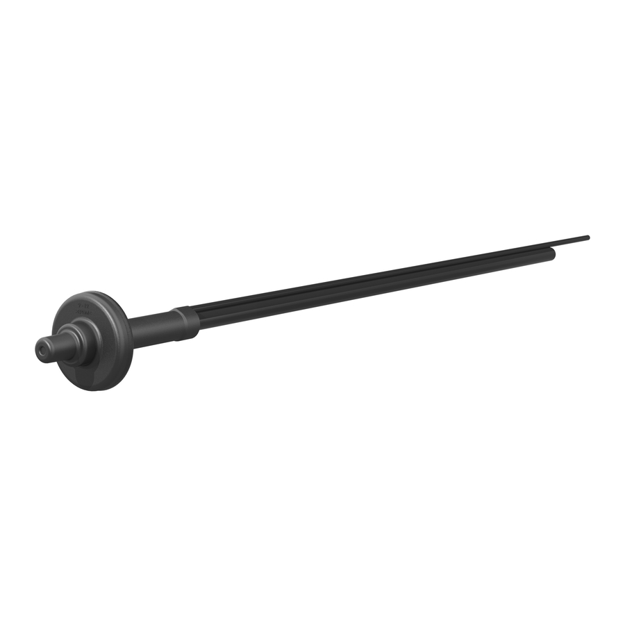
Description Pipe Tubular guide elbow External fl ange Resin fi ller hose Counter bearing Wall rosette Membrane hose Membrane opening Butyl strap 9–12 mm Scope of delivery The scope of delivery of the MIS 40/9 -12 for wall thicknesses of 200 - 900 mm includes: ... -
Page 4: Required Tool And Auxiliaries
Required tool and auxiliaries To install the MIS 40/9-12 correctly, you will need the following tools and auxiliaries in addition to the usual tools: • Drill, e.g. HILTI DD200 with drill bit or drilling tool (no fig.) for drill hole � 40–50 mm • Hauff MIS 40-SVS fast arrangement fixture, reusable, 1 included in each packing unit (= 10 pcs.) •... - Page 5 MIS installation Outside of building 7.1. Insert the MIS into the drill hole from the outside of the buil- ding. Arrange so that the resin injection hose is at the top. 7.2. Remove the protective film from the butyl strap of the rub- ber flange; push the MIS up to the external wall and gently press. The MIS rests against the outside of the building. Detail 7.3.
- Page 6 7.4. Insert the socket of the fast arrangement fixture into the drill hole. Then fix it using the vertical screw. The pipe is now fixed. 7.5. The MIS is tensioned against the external wall by tightening the two axial screws as far as they will go. Detail Screws are tightened as far as they will go Outside of building Checking on the outside of the building:...
- Page 7 7.6. Inside of building 150 mm Cut the resin filler hose to 150 mm (measured from the in- side wall of the building) with the aid of the side cutters (a shorter hose makes filling easier). Then firmly connect the mixing nozzle to the resin filling hose up to the stop. Detail 7.7. Unscrew the closing cover of the resin cartridge (Tangit iM 3000, 150 ml) and screw the cartridge into the mixing nozzle.
- Page 8 7.8. Remove the bottom cover from the resin cartridge. 7.9. Insert the resin cartridge into the cartridge gun. Fully inject the resin out of the cartridge into the MIS using even move- ments on the cartridge gun. During the curing time (5–7 min), do not dis- connect the entire resin system from the MIS wall entry! Detail...
- Page 9 7.11. The protruding pipe is shortened so that it is flush with the wall with the aid of a saw. 7.12. Outside of building From the outside of the building, a suitable tool (e.g. screwdriver) can now be used to pierce the membrane of the insertion opening. 7.13. It is advisable to grease the opening of the external flange and the SpeedNet pipe with lubricant so that the SpeedNet pipe slides smoothly.
- Page 10 7.15.1. Inside of building Guide the wall rosette on the inside of the building over the SpeedNet pipe and push it over the inlet pipe as far as it will go. 7.15.2. If walls are extremely uneven, slanted or cur- ved, the external ring of the wall rosette at the perforation is removed.
-
Page 11: Instructions De Sécurité
Sommaire 1 Informations générales et utilisation prévue 2 Instructions de sécurité 3 Description 4 Contenu de la livraison 5 Outils et auxiliaires requis 6 Préparation 7 Installation Informations générales et utilisation prévue MIS 40/9 -12 pour l'insertion d'1 tube SpeedNet ou câble pour l‘extérieur avec un diam�tre extérieur de 9 � 12 mm (tolérance ± 0,5 mm) pour des murs de 200 � 900 mm ou 900 � 1 200 mm. Instructions de sécurité Lors des travaux de montage, protéger la traversée murale contre tout endommagement, l'humidité et les saletés. Vérifi ... -
Page 12: Contenu De La Livraison
Description Tube Coude de guidage Bride extérieure Tube de remplissage de résine Rosace de raccordement Contre-palier mural Tuyau de membrane Bande en butyle Ouverture de membrane 9 -12 mm Contenu de la livraison Le contenu de la livraison pour la MIS 40/9 -12 pour murs de 200 � 900 mm comprend: 1 bride extérieure 40/9 -12 1 contre-palier 1 bande en butyle, 290 mm 1 tube de remplissage de résine, 950 mm 1 tuyau de membrane, 150 mm... - Page 13 �tre commandé séparément. Pour assurer une utilisation conforme, il convient d'utiliser le pistolet � mastic Ponal PP6/PP12. Il est disponible directement aupr�s de Hauff-Technik. Pour l'obtenir, contacter Hauff-Technik au +49 7322/1333-0 ou par e-mail � l'adresse office@hauff-technik.de. Préparation 6.1. Réalisation du perçage Percer un trou de � 40 � 50 mm. Le guidage peut �tre effectué manuellement ou au moyen d'un support de perceuse. Seuls des matériaux solides peuvent �tre percés. ...
- Page 14 Montage MIS Extérieur du bâtiment 7.1. Insérer la MIS dans le perçage � partir du côté extérieur du bâtiment. Placer le tube d‘injection de la résine en haut. 7.2. Retirer la feuille de protection de la bande en butyle de la bride en caoutchouc, pousser la MIS jusqu'au mur extérieur et appuyer légèrement.
- Page 15 7.4. Introduire la tubulure du dispositif de serrage rapide dans le perçage. Ensuite, fixer le dispositif au moyen de la vis vertica- le. Le tube est maintenant fixé. 7.5. Le serrage des deux vis axiales jusqu'� la butée serre la MIS contre le mur extérieur. Détail Les vis sont serrées jusqu'� la butée Extérieur du bâtiment Vérification côté extérieur du bâtiment: Au serrage du dispositif de serrage rapide, la bande en butyle s'écrase latéralement et Bande en butyle...
- Page 16 7.6. Intérieur du bâtiment 150 mm Couper le tube de remplissage de la résine � une longueur de 150 mm (mesurés � partir du mur intérieur du bâtiment) � l'aide d'une pince coupante diagonale (un tube plus court facilite le remplissage). Puis, raccorder solidement la buse de mélange au tube de remplissage, jusqu'� la butée. Détail 7.7. Dévisser le couvercle de fermeture de la cartouche de résine (Tangit iM 3000, 150 ml) et visser la cartouche sur la buse de mélange.
- Page 17 7.8. Retirer le couvercle de fond de la cartouche de résine. 7.9. Placer la cartouche de résine dans le pistolet. Injecter la to- talité de la cartouche de résine dans la MIS en actionnant le pistolet avec régularité. Ne pas retirer le syst�me d'injection de résine complet de la traversée murale MIS pendant tout le temps de durcissement (5 � 7 min).
- Page 18 7.11. Couper la portion de tube qui dépasse au ras du mur � l'aide d'une scie. 7.12. Extérieur du bâtiment La membrane de l'entrée peut maintenant �tre percée avec un outil adapté (par ex. un tournevis cruciforme) de l'extérieur du bâtiment. 7.13.
- Page 19 7.15.1. Intérieur du bâtiment Glisser la rosace de raccordement mural du côté intérieur du bâtiment sur le tube SpeedNet et jusqu'� la butée sur le tube d'insertion. 7.15.2. En présence de murs non lisses, inclinés ou bombés, la bague extérieure de la rosace de recouvrement mural est retirée au niveau de la perforation.
- Page 20 Hauff-Technik GmbH & Co. KG Robert-Bosch-Straße 9 Tel. +49 7322 1333-0 office@hauff-technik.de 89568 Hermaringen, GERMANY Fax +49 7322 1333-999 www.hauff-technik.de...
Need help?
Do you have a question about the MIS 40/9-12 and is the answer not in the manual?
Questions and answers