Table of Contents
Advertisement
Quick Links
Advertisement
Table of Contents

Related Manuals for IFM efector300 SD0523


Summary of Contents for IFM efector300 SD0523
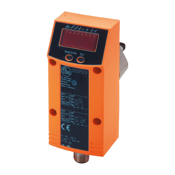
- Page 1 Operating instructions Compressed air meter SD0523...
-
Page 2: Table Of Contents
Contents 1 Preliminary note ���������������������������������������������������������������������������������������������������4 1�1 Symbols used ������������������������������������������������������������������������������������������������4 2 Safety instructions �����������������������������������������������������������������������������������������������5 3 Functions and features ����������������������������������������������������������������������������������������5 4 Function ���������������������������������������������������������������������������������������������������������������6 4�1 Process measured signals ����������������������������������������������������������������������������6 4�2 Volumetric flow monitoring �����������������������������������������������������������������������������6 4�3 Consumed quantity monitoring ����������������������������������������������������������������������6 4�3�1 Consumed quantity monitoring with pulse output ���������������������������������7 4�3�2 Consumed quantity monitoring with preset counter �����������������������������7 4�4 Temperature monitoring ���������������������������������������������������������������������������������7 4�5 Volumetric flow or temperature monitoring / switching function ���������������������8... - Page 3 9�1 Parameter setting in general �����������������������������������������������������������������������18 9�1�1 Extended menu 1 �������������������������������������������������������������������������������19 9�1�2 Extended menu 2 �������������������������������������������������������������������������������19 9�1�3 Locking / unlocking �����������������������������������������������������������������������������19 9�1�4 Timeout �����������������������������������������������������������������������������������������������20 9�2 Settings for volumetric flow monitoring ��������������������������������������������������������20 9�2�1 Adjustment to the internal pipe width ��������������������������������������������������20 9�2�2 Configure limit value monitoring with OUT1 ���������������������������������������20 9�2�3 Configure limit value monitoring with OUT2 ���������������������������������������20 9�2�4 Configure analogue value for volumetric flow �������������������������������������20 9�3 Settings for consumed quantity monitoring �������������������������������������������������21...
-
Page 4: Preliminary Note
10�2 Change display unit in the Run mode ��������������������������������������������������������27 10�3 Fault indications �����������������������������������������������������������������������������������������28 10�4 General operating conditions ���������������������������������������������������������������������28 11 Technical data and scale drawing ��������������������������������������������������������������������28 12 Factory setting �������������������������������������������������������������������������������������������������28 1 Preliminary note 1.1 Symbols used ► Instructions > Reaction, result […] Designation of pushbuttons, buttons or indications →... -
Page 5: Safety Instructions
2 Safety instructions • Please read this document prior to set-up of the unit� Ensure that the product is suitable for your application without any restrictions� • If the operating instructions or the technical data are not adhered to, personal injury and/or damage to property can occur�... -
Page 6: Function
4 Function 4.1 Process measured signals • The unit displays the current process values� • It generates 2 output signals according to the parameter setting� OUT1: 4 selection options Parameter setting - Switching signal for volumetric flow quantity limit (→ 9.2.2) value - or switching signal for flow velocity (→ 9.2.2) -
Page 7: 4�3�1 Consumed Quantity Monitoring With Pulse Output
• In addition the value before the last reset is saved� This value can also be displayed� The meter saves the totalled consumed quantity every 10 minutes� After a power failure this value is available as the current meter reading� If a time- controlled reset is set, the elapsed time of the set reset interval is also saved�... -
Page 8: 4�5 Volumetric Flow Or Temperature Monitoring / Switching Function
4.5 Volumetric flow or temperature monitoring / switching function OUTx changes its switching state if it is above or below the set switching limits (SPx, rPx)� The following switching functions can be selected: 4.5.1 Hysteresis function Normally open: [OUx] = [Hno] Normally closed: [OUx] = [Hnc] First the set point (SPx) is set, then the reset point (rPx) with the requested... -
Page 9: 4�6 Volumetric Flow Or Temperature Monitoring / Analogue Function
4.6 Volumetric flow or temperature monitoring / analogue function • Analogue start point [ASP] determines at which measured value the output signal is 4 mA� • Analogue end point [AEP] determines at which measured value the output signal is 20 mA� Minimum distance between [ASP] and [AEP] = 25 % of the final value of the measuring range�... -
Page 10: 4�8 Set Standard Conditions Of The Volume Flow
The unit can be set to different standard conditions: • Via the menu item [rEF�P] the standard pressure is set, which serves as a refer- ence for the measured and display values for volumetric flow (→ 9.5.8). • Via the menu item [rEF�T] the standard temperature is set, which serves as a reference for the measured and display values for volumetric flow (→ 9.5.9). -
Page 11: 5�2 Installation Conditions
• If compressed air is fed into the main pipe through parallel pipes, the unit should be mounted in the main pipe� • Installation downstream of the maintenance unit is also possible (if oil is used for the loads, the units must be mounted upstream of the oiler)� 5.2 Installation conditions Recommendation: ►... -
Page 12: 5�4 Installation Example Using The Process Adapter E40195
5.4 Installation example using the process adapter E40195 For an ideal alignment of the sensor's measuring probe to the direction of flow of the medium (fig� 4), observe the following notes on welding of the E40195 process adapter into the pipe: ►... -
Page 13: Electrical Connection
6 Electrical connection The unit must be connected by a qualified electrician� The national and international regulations for the installation of electrical equipment must be adhered to� Voltage supply according to EN 50178, SELV, PELV� ► Disconnect power� ► Connect the unit as follows: BK: black BN: brown OUT2... -
Page 14: Operating And Display Elements
7 Operating and display elements 1 2 3 4 5 6 7 8 Mode/Enter Set 1 to 8: indicator LEDs - LED 1 = current volumetric flow in standard cubic metres/minute(Nm /min)� - LED 2 = current volumetric flow in standard cubic metres/hour (Nm /h)�... -
Page 15: Menu
8 Menu 8.1 Menu structure /min Nm/h Nm/s °C = [Mode/Enter] / = [Set] = current meter reading in Nm / Nm * = saved meter reading in Nm... -
Page 16: 8�2 Explanation Of The Menu
8.2 Explanation of the menu SP1/rP1 Upper / lower limit value for volumetric flow� ImPS Pulse value� Pulse repetition active (= pulse output) or not active ImPR (= preset counter function)� Output function for OUT1 (volumetric flow or consumed quantity): - Switching signal for the limit values: hysteresis function or window function, either normally open or normally closed�... -
Page 17: 8�2�2 Extended Functions (2)
8.2.2 Extended functions (2) Extended menu 2� Setting of the inner pipe diameter in mm� CGA Calibration of the curve of measured values: define gradient� CAR Reset the calibration data� Standard pressure which serves as a reference for measured and display rEF�P values for volumetric flow�... -
Page 18: Parameter Setting
9 Parameter setting During parameter setting the unit remains in the operating mode� It continues to monitor with the existing parameters until the parameter setting has been com- pleted� 9.1 Parameter setting in general 3 steps must be taken for each parameter setting: Select the parameter ►... -
Page 19: 9�1�1 Extended Menu 1
9.1.1 Extended menu 1 ► Press [Mode/Enter] until [EF] is displayed� Mode/EnterSet ► Press [Set] briefly� > The first parameter of the submenu is Mode/EnterSet displayed (here: [HI])� 9.1.2 Extended menu 2 ► Press [Mode/Enter] until [EF] is displayed� ► Press [Set] briefly� >... -
Page 20: 9�1�4 Timeout
9.1.4 Timeout If no button is pressed for 15 s during parameter setting, the unit returns to the operating mode with unchanged values� 9.2 Settings for volumetric flow monitoring 9.2.1 Adjustment to the internal pipe width ► Select [diA] and set a numerical value in mm�... -
Page 21: 9�3 Settings For Consumed Quantity Monitoring
9.3 Settings for consumed quantity monitoring 9.3.1 Configure quantity monitoring via pulse output ► Select [OU1] and set [ImP]� ► Select [ImPS] and set the volumetric flow quantity at which 1 pulse is provided (→ 9.7). ► Select [ImPR] and set [YES] >... -
Page 22: 9�4 Settings For Temperature Monitoring
9.4 Settings for temperature monitoring 9.4.1 Configure limit value monitoring with OUT2 ► Select [SEL2] and set [TEMP]� ► Select [OU2] and set the switching function� - [Hno] = hysteresis function/normally open� - [Hnc] = hysteresis function/normally closed� - [Fno] = window function/normally open� - [Fnc] = window function/normally closed�... -
Page 23: 9�5�2 Configure Standard Display
9.5.2 Configure standard display ► Select [SELd] and set the standard unit of measurement: - [FLOW] = the current volumetric flow value in the standard unit of measurement is displayed� - [TOTL] = the current meter reading in Nm or Nm x 10 is displayed�... -
Page 24: 9�5�7 Reset Calibration Data
9.5.7 Reset calibration data ► Select [CAr]� ► Press and hold [SET] until [----] is displayed� ► Briefly press [Mode/Enter]� > The values are reset to the factory setting (CGA = 100)� 9.5.8 Set standard pressure which serves as a reference for measured and display values for volumetric flow ►... -
Page 25: 9�7 Set Preset Counter / Pulse Value (Imps)
9.7 Set preset counter / pulse value (ImPS) The unit has 4 setting ranges: Step Display Value increment 0 0 0 1 ��� 9 9 9 9 1���9999 Nm³ 1 Nm³ 4 + 6 1 0 �0 0 ��� 9 9 �9 9 10 000���99 990 Nm³... - Page 26 ► Press and hold The flashing digit is increased, 9 is followed by 0 and the next [Set]� digit on the left becomes active� 8 1� 8 3 [Set] permanently pressed 8 1� 9 3 [Set] held pressed 8 1� 0 3 If digit 1 is increased this way, the display changes to the next higher setting range (9 is followed by 10;...
-
Page 27: Operation
10 Operation Correct operation and compliance with the measurement accuracy can only be ensured if the environmental conditions specified in the technical data ((→ www. ifm.com → Data sheet search → Enter article number) are adhered to. Ensure that the maximum pressure range, measuring range and permitted ambient tem- perature are not exceeded� After power-on and expiry of the power-on delay time (approx� 0�5 s) the unit is in the Run mode (= normal operating mode)�... - Page 28 • If necessary, clean them at regular intervals� To do so, use a suitable cleaning liquid (e�g� alcoholic solution)� • Avoid mechanical damage to the measuring probes� 11 Technical data and scale drawing Technical data and scale drawing at www�ifm�com� 12 Factory setting Factory setting User setting...
- Page 29 (FLOW) SP2 (TEMP) 24.0 rP2 (TEMP) 23.8 ASP (FLOW) 0.00 AEP (FLOW) 2110 ASP (TEMP) AEP (TEMP) 60.0 DIn2 +EDG FOU1 FOU2 nm3h SELd FLOW SEL2 FLOW 0.04 rEF.P 1013 rEF.T More information at www�ifm�com...
Need help?
Do you have a question about the efector300 SD0523 and is the answer not in the manual?
Questions and answers