
Related Manuals for IFM efector300 SI0102


Summary of Contents for IFM efector300 SI0102
- Page 1 Bedienungsanleitung Operating instructions Notice utilisateurs Strömungswächter Flow monitor Contrôleur de débit SI0102 SI0505...
- Page 2 Kurzanleitung • Installieren Montage → Seite 6, elektrischer Anschluß → Seite 8. • HI-Abgleich Schalten Sie die Betriebsspannung ein. Nach etwa 15 s ist das Gerät betriebsbereit. Lassen Sie das Medium mit der gewünschten Maximal- strömung (HI) in der Anlage fließen. Drücken Sie die Taste Learn/Set und halten Sie sie gedrückt.
- Page 3 Bedien- und Anzeigeelemente Einstelltasten MODE / LEARN / ENTER FLOW RATE Betriebsanzeige Betriebsanzeige (Run-Modus) Aktuelle Strömung im Anzeigebereich (grüner LED-Balken) Überströmung (LED 9 blinkt) Unterströmung (LED 0 blinkt) Anzeige der Schaltpunkte (SPx): LED orange: Strömung ≥ SPx; LED rot: Strömung < SPx Einstelltasten Mode / Enter: •...
- Page 4 Menüstruktur Run-Modus Geräte- Abgleich / funktionen Werkseinstellung (ENTER-Taste) (SET-Taste) Abgleich Maximalströmung Schaltpunkt 1 einstellen >5...<10s >5s >5s Abgleich Minimalströmung >10...<15s Schaltpunkt 2 einstellen Rücksetzen Werkseinstellung >5s >15...<20s Überwachung Überströmung LED = grün LED = orange LED = rot Sachnr. 701947/00 SI0102/SI0505...
-
Page 5: Table Of Contents
Inhalt Bestimmungsgemäße Verwendung ....Seite 5 Montage ........Seite 6 Elektrischer Anschluß... -
Page 6: Montage
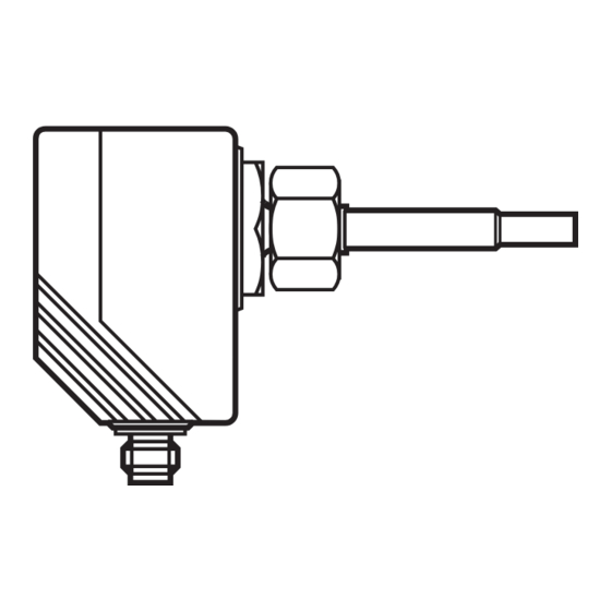
Montage Das Gerät ist adaptierbar an unterschiedliche Prozeßanschlüsse. (Adapter sind gesondert als Zubehör zu bestellen). • Montieren Sie das Gerät bei waagerecht verlaufenden Rohren möglichst seitlich (Abb 1). Bei Montage von unten sollte die Rohrleitung frei von Ablagerungen sein. Bei Montage von oben sollte die Rohrleitung vollständig mit dem zu überwachenden Medium gefüllt sein. - Page 7 Gewinde M18 x 1,5 1. Fetten Sie die Überwurfmutter (3) und alle Gewinde mit Schmier- paste ein, um mehrmaliges Lösen und Festziehen zu gewährleisten. Achtung: Es darf kein Fett auf die Sensorspitze (A) gelangen. 2. Schrauben Sie den passenden Adapter (2) auf den Prozeßanschluß (1). 3.
- Page 8 2 WH 3 BU 1 BN Adernfarben bei ifm-Kabeldosen: 1 = BN (braun), 2 = WH (weiß), 3 = BU (blau), 4 = BK (schwarz) Nach dem Einschalten der Versorgungsspannung leuchten alle LEDs auf und verlöschen wieder schrittweise.* Danach ist das Gerät betriebsbereit.
-
Page 9: Programmieren
Programmieren I I Überwachungsbereich Strömung einstellen HI-Abgleich • Medium mit gewünschter Maximalströmung in der Anlage fließen lassen. • >5...<10 s lang Taste Learn/Set drücken (= Abgleich auf Maximalströmung / oberes Ende des Überwachungsbereichs). Optional: LO-Abgleich Der HI-Abgleich genügt für die meisten wasserbasierten Applikationen. -
Page 10: Inbetriebnahme / Betrieb / Wartung
I I Für die Einstellvorgänge gilt: • Wird während des Einstellvorgangs 15 s lang keine Taste gedrückt, geht das Gerät mit unveränderten Werten in den Betriebsmodus zurück. • Ist der Abgleich nicht möglich, blinken alle roten LEDs. Danach geht das Gerät mit unveränderten Werten in den Betriebsmodus zurück. I I Verriegeln / Entriegeln Das Gerät läßt sich verriegeln, so daß... -
Page 11: Technische Daten
Technische Daten Betriebsspannung [V] ......20 ... 36 DC Strombelastbarkeit [mA] ... 2 x 250; Kurzschlußschutz, getaktet; verpolungssicher / überlastfest Spannungsabfall [V] . -
Page 12: Einstelldiagramme / Technik-Information
Einstelldiagramme / Technik-Information I I Überwachungsbereich Strömung einstellen Der Erfassungsbereich (Fenster) wird festgelegt durch • Abgleich gewünschte Maximalströmung (HI-Teach) = oberes Ende des Fensters. Dieser Abgleich genügt für die meisten wasserbasierten Sensor- Applikationen. signal • Abgleich gewünschte Minimalströmung / Strömungs- stillstand (LO-Teach) = unteres Ende des Fensters;... - Page 13 • Abgleich auf Minimalströmung / Strömungsstillstand (LO-Teach), optional Das Gerät erfaßt die vorhandene Strömung und setzt diesen Wert als unteren Anzeigewert für das LED-Display. Im Betriebszustand blinkt die erste grüne LED (LED 0), wenn die Strömung unter diesen Wert fällt (bzw. wenn Strömungsstillstand eintritt). ACHTUNG: LO-Teach darf nur nach HI-Teach durchgeführt werden.
- Page 14 I I Schaltpunkte einstellen Schaltpunkt 1 (SP1) = unterer Wert, Einstellbereich: LED 0 ... SP2 Schaltpunkt 2 (SP2) = oberer Wert, Einstellbereich: SP1 ... LED 9 Drücken Sie die Taste Mode/Enter . Der aktuelle Schaltpunkt wird angezeigt: 1 mal (= Einstellen SP1) leuchtende LED: Grobeinstellung, 2 mal (= Einstellen SP2) blinkende LED: Feineinstellung.
- Page 15 I I Überwachung auf Überströmung Mit dieser Funktion können Sie die Position des Anzeigefensters im Überwachungsbereich festlegen: Verschieben Sie die LED für den obe- ren Anzeigewert auf die Position 8, 7, 6 oder 5. Bei maximaler Betriebsströmung leuchten alle LEDs von 0 bis zu dieser LED. Die LEDs oberhalb dieses Bereichs signalisieren Überströmung.
- Page 16 I I Werkseinstellung wieder herstellen (Reset) Drücken Sie die Taste Learn/Set und halten Sie sie gedrückt. Die grünen LEDs rechts und links >15...<20 s blinken, nach 5 s füllt sich der LED-Balken (grün) von links nach rechts, nach weiteren 5 s füllt sich der LED-Balken (grün) von rechts nach links, nach weiteren 5 s füllt sich der...
- Page 17 Hysteresefunktion Strömung Maximalströmung Schaltpunkt (SPx) Hysterese Minimalströmung Steigt die Strömungsgeschwindigkeit, schalten der jeweilige Ausgang bei Erreichen des Schaltpunkts (SPx). Sinkt die Strömungsgeschwindigkeit wieder, schaltet der Ausgang zurück, wenn der Wert “SPx minus Hysterese” erreicht ist. Die Hysterese wird wesentlich beeinflußt von der Wahl des Arbeitsbereichs auf der Empfindlichkeitskurve des Sensors: •...
- Page 18 Brief adjustment instructions • Installation Mounting → page 22, electrical connection → page 24. • HI-Teach Apply the operating voltage. After approx. 15 s the unit is ready. Allow the medium to flow through the system at the required maximmum flow rate (HI). Press the Learn/Set button and keep it pressed.
- Page 19 Controls and visual indication setting buttons MODE / LEARN / ENTER FLOW RATE function display Function display (Run mode) current flow within the display range (LED bar green) excess flow (LED 9 flashes) underflow (LED 0 flashes) Indication of the switch points (SPx): LED orange: flow ≥...
- Page 20 Menu structure Run mode Adjustment / Unit functions factory setting (ENTER button) (SET button) Setting the switch point 1 Adjustment to maximum flow >5...<10s >5s >5s Adjustment to minimum flow >10...<15s Setting the switch point 2 Factory reset >5s >15...<20s Monitoring excess flow LED = green LED = orange...
-
Page 21: Function And Features
Contents Function and features ......page 21 Installation ........page 22 Electrical connection . -
Page 22: Installation
Installation The unit is adaptable for various process fittings (adapters to be ordered separately as accessories). • In the case of horizontal pipes mount the unit from the side, if pos- sible (fig. 1). When the unit is to be mounted at the bottom of the pipe, it should be free from deposits. - Page 23 thread M18 x 1.5 1. Lubricate the nut (3) and all threads with grease to ensure the nut can be loosened and tightened several times. Note: No grease must be applied to the sensor tip (A). 2. Screw the suitable adapter (2) onto the process fitting (1). 3.
-
Page 24: Electrical Connection
2 WH 3 BU 1 BN Core colours of ifm sockets: 1 = BN (brown), 2 = WH (white), 3 = BU (blue), 4 = BK (black) When the supply voltage is applied, all LEDs light and go off one after the other.* The unit is then ready for operation. -
Page 25: Programming
Programming I I Setting of the detection range HI-Teach • Allow the medium to flow through the system at the required maxi- mum flow rate. • Press the Learn/Set button for >5...<10 s (= adjustment to maxi- mum flow / upper limit of the detection range). Optional: LO-Teach The HI-Teach is sufficient for the majority of waterbased applica- tions. -
Page 26: Installation And Set-Up / Operation / Maintenance
I I The following applies to all setting procedures: • If no button is pressed for 15 s during the setting procedure, the unit returns to the operating mode with the parameter values unchanged. • If adjustment has not been possible, all the red LEDs flash. The unit returns to the operating mode with the parameter values unchanged. -
Page 27: Technical Data
Technical data Operating voltage [V] ......20 ... 36 DC Current rating [mA] ....2 x 250; short-circuit protection; reverse polarity protection / overload protection Voltage drop [V] . -
Page 28: Programming Diagrams / Technical Information
Programming diagrams / Technical information I I Setting of the detection range The detection range (window) is determined by: • Adjustment to the required maximum flow (HI-Teach) = upper limit of the window. This setting is sufficient for the majority of waterbased appli- sensor cations. - Page 29 • Adjustment to minimum flow / flow standstill (LO-Teach), optional The unit detects the current flow and sets this value as the minimum display value for the LED display. In normal operation the first green LED (LED 0) flashes when the flow falls below this value (or when it comes to a standstill).
- Page 30 I I Setting of the switch points Switch point 1 (SP1) = lower value, setting range: LED 0 ... SP2 Switch point 2 (SP2) = upper value, setting range: SP1 ... LED 9 Press the Mode/Enter button. The current switch point is indicated: 1 time (= setting of SP1) LED lit: coarse setting, LED...
- Page 31 I I Monitoring excess flow With this function the position of the display window within the detection range can be defined: Shift the LED for the maximum dis- play value to position 8, 7, 6 or 5. In the case of maximum flow all LEDs from 0 up to this LED are lit.
- Page 32 I I Return to factory setting Press the Learn/Set button and keep it pressed. The green LEDs on the right and >15...<20 s on the left flash, after 5 s the LED bar (green) fills from left to right, after a further 5 s the LED bar (green) fills from right to left, after a further 5 s the LED bar (orange) fills from left to right...
- Page 33 Hysteresis function flow maximum flow switch point (SPx) hysteresis minimum flow When the flow rises, the outputs switch when the corresponding switch point (SPx) has been reached. When the flow falls again, the output switches back when the value "SPx minus hysteresis" has been reached.. The hysteresis is considerably influenced by the choice of the operat- ing range on the sensitivity curve of the sensor: •...
- Page 34 Notice succincte de réglage • Installation Montage → page 38, raccordement électrique → page 40. • HI-Teach Mettre l’appareil sous tension L'appareil est opérationnel après env. 15 s. Le débit du fluide doit être à la valeur maximale (HI) souhaité. Appuyer sur le bouton Learn/Set et le maintenir appuyé.
- Page 35 Eléments de service et d’indication boutons-poussoir de réglage MODE / LEARN / ENTER FLOW RATE indication de fonction Indication de fonction (Mode RUN) débit actuel du fluide dans la plage de détection (rampe LED verte) débit excessif (LED 9 clignote) chute du débit (LED 0 clignote) Indication du seuils de commutation (SPx): LED orange: débit ≥...
- Page 36 Structure du menu Mode Run Fonctions d’appareil Réglage (Bouton ENTER) (Bouton SET) Réglage sur débit maximum Seuil de commutation 1 >5...<10s >5s >5s Réglage sur débit minimum >10...<15s Seuil de commutation 2 Réglages de base >5s >15...<20s Surveiller un débit excessif LED = verte LED = orange LED = rouge...
-
Page 37: Fonctionnement Et Caractéristiques
Contenu Fonctionnement et caractéristiques ....page 37 Montage ........page 38 Raccordement électrique . -
Page 38: Montage
Montage L'appareil est adaptable à différents types de raccords process (adap- tateurs à commander séparément comme accessoires). • Dans le cas des tubes horizontaux monter l'appareil latéralement, si possible (fig. 1). Lorsque l'appareil est monté par le bas le tube doit être dégagé de dépôts. - Page 39 filetage M18 x 1,5 1. Graisser l'écrou (3) et les filetages afin d'assurer que l'écrou peut être desserré et serré plusieurs fois. Remarque: Aucune graisse ne doit être appliquée au bout de la sonde (A). 2. Visser l'adaptateur approprié (2) sur le raccord process (1). 3.
-
Page 40: Raccordement Électrique
3 BU 1 BN Couleurs des fils conducteurs des connecteurs femelles ifm: 1 = BN (brun), 2 = WH (blanc), 3 = BU (bleu), 4 = BK (noir). Dès la mise sous tension toutes les LED s'allument et s'éteignent l'une après l'autre.* L'appareil est ensuite opérationnel. -
Page 41: Programmation
Programmation I I Réglage de la plage de détection débit HI-Teach • Le débit du fluide doit être à la valeur maximale souhaité. • Appuyer sur le bouton Learn/Set pendant >5...<10 s (= réglage sur débit maximum). Ce réglage suffit pour la plupart des applications à base d'eau. Option: réglage sur débit minimum (LO-Teach). -
Page 42: Mise En Service / Fonctionnement / Maintenance
I I Pour les réglages, les points suivants sont valables: • Si lors du réglage, aucun bouton n'est appuyé pendant 15 s, l'appareil redevient opérationnel sans aucune modification des valeurs. • Si le réglage est impossible, les LED rouges clignotent. Puis l'appa- reil redevient opérationnel sans aucune modification des valeurs. -
Page 43: Données Techniques
Données techniques Tension d'alimentation [V] ......20 ... 36 DC Courant de sortie [mA] ....2 x 250; protégé: courts-circuits protégé: inv. -
Page 44: Diagrammes De Réglage / Informations Techniques
Diagrammes de réglage / Informations techniques I I Réglage de la plage de détection débit La plage de détection est déter- minée par: • Réglage sur débit maximum souhaité (HI-Teach) . Ce réglage suffit pour la plu- part des applications à base signal d'eau. - Page 45 • Réglage sur débit minimum ou débit nul (LO-Teach; optionnel) L'appareil détecte le débit existant et l'utilise comme valeur minimale pour l'affichage à LED. En fonctionnement la première LED verte (LED 0) clignote lorsque le débit du fluide tombe en-dessous de cette valeur (ou lorsque le débit est nul).
- Page 46 I I Réglage du seuils de commutation Seuil 1 (SP1) = valeur basse, plage de réglage: LED 0 ... SP2 Seuil 2 (SP2) = valeur haute, plage de réglage: SP1 ... LED 9. Appuyer sur le bouton Mode/Enter. Le seuil de commu- tation actuel est affiché: 1 fois (= réglage du SP1) LED allumée: réglage grossier,...
- Page 47 I I Surveiller un débit excessif Grâce à cette fonction, une fenêtre d'affichage dans la plage de détection peut être définie: Déplacer la LED indiquant la valeur maxi- male à la position 8, 7, 6 ou 5. En débit maximum toutes les LED de cette échelle sont allumées.
- Page 48 I I Récupérer les réglages de base effectués en usine S'assurer d'être dans le mode Run débit. Appuyer sur le bouton Learn/Set et le maintenir appuyé. Les LED vertes à droite et à gauche >15...<20 s clignotent; après 5 s la rampe de LED s'allume de gauche à...
- Page 49 Fonction hystérésis débit débit maximum seuil de Hystérésis commutation (SPx) débit minimum Si le débit augmente, les sorties commutent lorsque le seuil de com- mutation correspondant (SPx) est atteint. Si le débit diminue de nouveau, la sortie ne commute que lorsque la valeur “SPx minus hystérésis”...
Need help?
Do you have a question about the efector300 SI0102 and is the answer not in the manual?
Questions and answers