Table of Contents
Advertisement
Quick Links
Advertisement
Table of Contents

Related Manuals for IFM SI0558


Summary of Contents for IFM SI0558
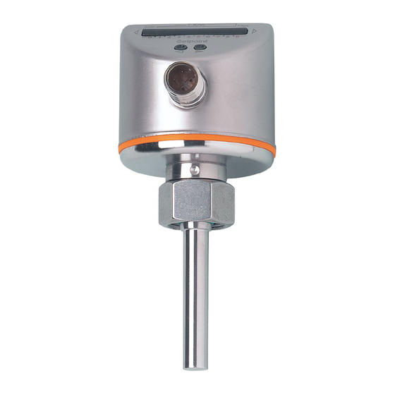
- Page 1 Operating instructions Flow monitor SI0558 SI0564...
-
Page 2: Table Of Contents
SI0558 SI0564 Flow monitor Contents Preliminary note ............. -
Page 3: Preliminary Note
Flow monitor SI0558 SI0564 1 Preliminary note You will find instructions, technical data, approvals and further information using the QR code on the unit / packaging or at www.ifm.com. 1.1 Symbols used Requirement Instructions Reaction, result [...] Designation of keys, buttons or indications... -
Page 4: Safety Instructions
SI0558 SI0564 Flow monitor 2 Safety instructions • The unit described is a subcomponent for integration into a system. – The system architect is responsible for the safety of the system. – The system architect undertakes to perform a risk assessment and to create documentation in accordance with legal and normative requirements to be provided to the operator and user of the system. -
Page 5: Intended Use
Flow monitor SI0558 SI0564 3 Intended use The device monitors liquids and gases. The device detects flow based on the calorimetric measuring principle and switches the output. The switch point is adjustable. The typical response time of the device is 1 ... 10 s. It can be influenced by the setting of the switch point: •... -
Page 6: Installation
SI0558 SI0564 Flow monitor 4 Installation CAUTION During installation or in case of mechanical failure, high pressure or hot media can leak from the system. w Risk of injury caused by pressure or burns. u Ensure that the system is free of pressure during installation. -
Page 7: Impermissible Installation Position
4.3 Process connection Using process adapters the unit can be adapted to different process connections. A correct fit of the unit and ingress resistance of the connection are only ensured using ifm adapters. For small flow rates, ifm adapter blocks are available. - Page 8 SI0558 SI0564 Flow monitor u Place the flow monitor onto the adapter and tighten the nut. Tightening torque 25 Nm. Ensure that the unit is correctly oriented.
-
Page 9: Electrical Connection
Flow monitor SI0558 SI0564 5 Electrical connection The unit must be connected by a qualified electrician. u Observe the national and international regulations for the installation of electrical equipment. u For the output circuit take the same protective measures as for the supply circuit. -
Page 10: Operating And Display Elements
SI0558 SI0564 Flow monitor 6 Operating and display elements Operation indication • The LEDs 0...9 represent the range of the monitored flow. • The green LEDs show the current flow. • An illuminated LED shows the position of the switching point: –... -
Page 11: Set-Up
Flow monitor SI0558 SI0564 7 Set-up u Switch on the supply voltage. w All LEDs light and go out again step by step. During this time the output is closed. w The device is in the operating mode. -
Page 12: Settings
SI0558 SI0564 Flow monitor 8 Settings The switch point is preset Ò Technical data at www.documentation.ifm.com. The preset switch point can be changed. 8.1 Switch point setting Changing the preset switch point is useful in the following cases: • The flow fluctuates strongly or pulsates. - Page 13 Flow monitor SI0558 SI0564 u Press both setting keys for 10 seconds. w The display goes off. w The unit is locked. u For unlocking repeat the process.
-
Page 14: Operation
SI0558 SI0564 Flow monitor 9 Operation After power on, the unit is ready for operation. The device detects the flow and switches the output according to the setting. • Output closed (LED = yellow) if flow ≥ switch point. • Output open (LED = red), if volumetric flow quantity < switch point. -
Page 15: Troubleshooting
Flow monitor SI0558 SI0564 10 Troubleshooting Indication Description Corrective measures u Unlock unit. See Lock / unlock The sensor is permanently locked. (Ò / 12) After approx. 0.6 seconds, the last oper- ating status is indicated. The display goes OFF briefly (LEDs go off when a button is pressed) Operating voltage too low (<... -
Page 16: Maintenance, Repair And Disposal
SI0558 SI0564 Flow monitor 11 Maintenance, repair and disposal Only the manufacturer is allowed to repair the unit. u Ensure that the sensor tip is free from build-up: • Check the sensor tip for build-up one month after set-up. • Repeat check regularly. Determine check intervals based on the application.
Need help?
Do you have a question about the SI0558 and is the answer not in the manual?
Questions and answers