Advertisement
Quick Links
HALSEY TAYLOR OWNERS MANUAL
OVL-I I
TM
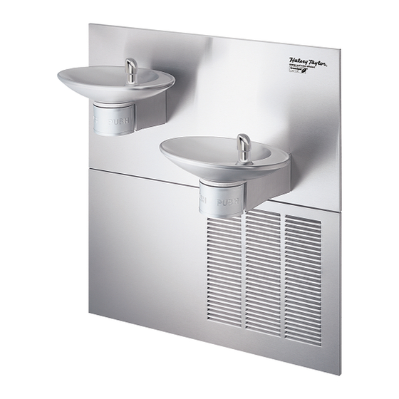
Fig.1 – OVL-II-EREE-Q
Figure
1
2
3
4
INSTALLER
NOTE: It is common practice to ground electrical hardware such as telephones, computers and other devices to
available water lines. This can, however, cause electrical feedback in the plumbing circuit, which results in an
"electrolysis" effect occurring in the fountain. This may result in water which has a metallic taste to it or has a
noticeable increase in the metallic content of the water.
When inspecting plumbing circuit, remember the line may be grounded some distance from the installation,
and may occur outside the building or area in which the unit is being installed.
This condition can be avoided (in most cases) by using recommended materials during installation. Any drain
fittings provided by the installer should be made of plastic which will electronically isolate the fountain from the
remainder of the building's plumbing circuits.
OVLEREEQ*G OVLSREEQ*G OVLESREEQ*G OVLSEREEQ*G
Series Electronic Eye Barrier-Free Water Coolers
Refrigerated Fountains with Back Panel
Fig. 2 – OVL-II-SREE-Q
Model
OVL-II-EREE-Q
OVL-II-SREE-Q
OVL-II-SEREE-Q
OVL-II-ESREE-Q
Review these instructions before beginning installation. Be sure that installation
conforms to all plumbing, electrical and other applicable codes.
When installation is complete, ensure these instructions are left in the plastic bag
provided inside the installed unit for future reference.
Service to be performed by authorized service personnel only.
Fig. 3 – OVL-II-SEREE-Q
Description
OVL-II Series - Extended Reach
OVL-II Series - Standard Reach
OVL-II Series - Dual Installation
OVL-II Series - Dual Installation
1
Fig. 4 – OVL-II-ESREE-Q
97882C - (Rev. F - 7/09)
Advertisement

Subscribe to Our Youtube Channel
Related Manuals for Halsey Taylor OVL-I I Series


Summary of Contents for Halsey Taylor OVL-I I Series
- Page 1 OVLEREEQ*G OVLSREEQ*G OVLESREEQ*G OVLSEREEQ*G HALSEY TAYLOR OWNERS MANUAL OVL-I I Series Electronic Eye Barrier-Free Water Coolers Refrigerated Fountains with Back Panel Fig.1 – OVL-II-EREE-Q Fig. 2 – OVL-II-SREE-Q Fig. 3 – OVL-II-SEREE-Q Fig. 4 – OVL-II-ESREE-Q Figure Model Description OVL-II-EREE-Q...
- Page 2 OVLEREEQ*G OVLSREEQ*G OVLESREEQ*G OVLSEREEQ*G Installation Package 3/8" O.D. UNPLATED 1/4" O.D. TUBE BUILDING WATER The components for installation are packed in three COPPER TUBE CONNECT WATER INLET INLET separate boxes, regardless of the type of unit being COLD WATER SUPPLY TO COOLER installed.
- Page 3 OVLEREEQ*G OVLSREEQ*G OVLESREEQ*G OVLSEREEQ*G Parts List Continued OVL-II OVL-II OVL-II OVL-II Part No. Description EREE-Q SREE-Q SEREE-Q ESREE-Q Fig. Item 27008C Reaction Bracket 70856C Screw - #10-24 x .38 PHMS 70854C Rod - Pivot 50198C Bushing Snap 51667C Bumper - Regulator Valve Assy 28327C Arm - Regulator Activating 28326C...
- Page 4 OVLEREEQ*G OVLSREEQ*G OVLESREEQ*G OVLSEREEQ*G Models OVL-II SEREE-Q – OVL-II ESREE-Q Cut a rectangular wall opening 37-1/2” (953 mm) W x 37-3/4” H (959 mm) and 4-1/2” (114 mm) above the floor line (see Figure 7). The dimensions are required to obtain proper rim and bubbler heights for compliance with ANSI standard A117.1.
- Page 5 OVLEREEQ*G OVLSREEQ*G OVLESREEQ*G OVLSEREEQ*G Install the frame assembly squarely in wall opening Attach the chiller shelf support rods to the right side of with frame upright support edges flush with the finished wall the frame uprights at the second set of holes counting from face.
- Page 6 OVLEREEQ*G OVLSREEQ*G OVLESREEQ*G OVLSEREEQ*G Models OVL-II EREE-Q – OVL-II SREE-Q Cut a rectangular wall opening 18-3/4” (475 mm) W x 37-3/4” H (959 mm) and 4-1/2” (114 mm) above the floor line (see Figure 10). The dimensions are required to obtain proper rim and bubbler heights for compliance with ANSI standard A117.1.
- Page 7 OVLEREEQ*G OVLSREEQ*G OVLESREEQ*G OVLSEREEQ*G Install the frame squarely in wall opening with frame Secure the frame sides and top to the wall opening using upright edges flush with the finished wall surface. Place (10) 5/16” bolts or screws (not provided). shelf inside frame and line up the (2) holes on each.
-
Page 8: Required Tools And Materials
OVLEREEQ*G OVLSREEQ*G OVLESREEQ*G OVLSEREEQ*G REQUIRED TOOLS AND MATERIALS Install fountain. Remove bottom access panel on underside of fountains and SAVE the screws. Mount the fountains to the upper panel and frame with These tables show special tools and/or additional materials (not (4) 5/16”... - Page 9 OVLEREEQ*G OVLSREEQ*G OVLESREEQ*G OVLSEREEQ*G 11. Turn on water supply and check for leaks. Release air from tank by interrupting infrared beam; a steady stream of water assures all air is removed. The sensor has a 30 second maximum ON time. It may be necessary to step away from beam a few times to allow chiller tank to fill.
-
Page 10: Troubleshooting And Maintenance
OVLEREEQ*G OVLSREEQ*G OVLESREEQ*G OVLSEREEQ*G TROUBLESHOOTING & MAINTENANCE Orifice Assembly: Mineral deposits on orifice can cause water flow to spurt or not regulate. Mineral deposits may be removed from the orifice by poking with a small round file not over 1/8” diameter, or using a small diameter wire. - Page 11 OVLEREEQ*G OVLSREEQ*G OVLESREEQ*G OVLSEREEQ*G See Fig. 22 3, 4 See Fig. 20 See Fig. 21 Figure 24 – Push Bar Fountain Assembly - Side View 97882C - (Rev. F - 7/09)
- Page 12 OVLEREEQ*G OVLSREEQ*G OVLESREEQ*G OVLSEREEQ*G Connect To Sensor Assy. Figure 25 – View of Electronic Sensor Figure 26 – View of Solenoid Valve 3, 4 Figure 27 – Electronic Sensor Fountain Assembly - Side View 2222 CAMDEN COURT OAK BROOK, IL 60523 630.574.3500 REPAIR SERVICE INFORMATION TOLL FREE NUMBER 1.800.260.6640 PRINTED IN U.S.A.
Need help?
Do you have a question about the OVL-I I Series and is the answer not in the manual?
Questions and answers