
Related Manuals for Supermicro SC513B Series


Summary of Contents for Supermicro SC513B Series
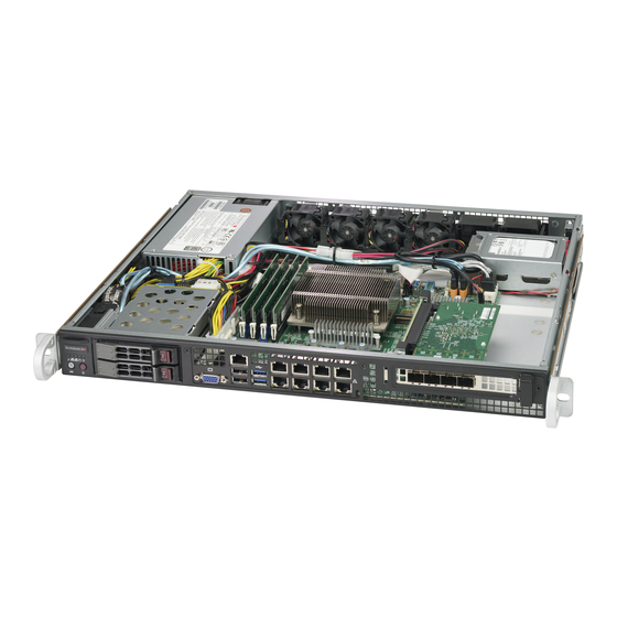
- Page 1 SC513B Chassis SC513BTQC-350B SC513BTQC-350WB SC513BTQC-505WB USER’S MANUAL Revision 1.0...
- Page 2 State of California, USA. The State of California, County of Santa Clara shall be the exclusive venue for the resolution of any such disputes. Supermicro's total liability for all claims will not exceed the price paid for the hardware product.
- Page 3 This document lists compatible parts available when this document was published. Refer to the Supermicro web site for updates on supported parts and configurations.. Warnings Special attention should be given to the following symbols used in this manual.
-
Page 4: Table Of Contents
Contents Chapter 1 Introduction 1-1 Overview ........................... 1-1 1-2 Shipping List ........................1-1 1-3 Contacting Supermicro ..................... 1-2 1-4 Returning Merchandise for Service .................. 1-3 Chapter 2 Standardized Warning Statements for AC Systems Chapter 3 Chassis Components 3-1 Overview ........................... 3-1 3-2 Components ........................ - Page 5 Preface 5-9 Installing Expansion Cards ..................... 5-12 5-10 Checking the Airflow ..................... 5-13 Installation Complete ..................... 5-13 Chapter 6 Rack Installation 6-1 Overview ........................... 6-1 6-2 Unpacking the System ..................... 6-1 6-3 Preparing for Setup ......................6-1 Choosing a Setup Location ..................... 6-1 Rack Precautions ......................
- Page 6 SC513B Chassis User's Manual Notes...
-
Page 7: Chapter 1 Introduction
Tooless serviceability and quick release sliding rails are also available for use in HPC and data center environments. 1-2 Shipping List Please visit Supermicro's website for the latest shipping lists and part numbers for your par- ticular chassis model: www.supermicro.com Power... -
Page 8: Contacting Supermicro
SC513B Chassis User's Manual 1-3 Contacting Supermicro Headquarters Address: Super Micro Computer, Inc. 980 Rock Ave. San Jose, CA 95131 U.S.A. Tel: +1 (408) 503-8000 Fax: +1 (408) 503-8008 marketing@supermicro.com (General Infor- Email: mation) support@supermicro.com (Technical Sup- port) Website: www.supermicro.com... -
Page 9: Returning Merchandise For Service
For faster service, RMA authorizations may be requested online (http://www.supermicro.com/ support/rma/). Whenever possible, repack the chassis in the original Supermicro carton, using the original packaging material. If these are no longer available, be sure to pack the chassis securely, using packaging material to surround the chassis so that it does not shift within the carton and become damaged during shipping. - Page 10 SC513B Chassis User's Manual Notes...
-
Page 11: Chapter 2 Standardized Warning Statements For Ac Systems
Supermicro's Technical Support department for assistance. Only certified technicians should attempt to install or configure components. Read this appendix in its entirety before installing or configuring components in the Supermicro chassis. These warnings may also be found on our website at http://www.supermicro.com/about/... - Page 12 Chapter 2: Standardized Warning Statements for AC Systems Warnung WICHTIGE SICHERHEITSHINWEISE Dieses Warnsymbol bedeutet Gefahr. Sie befinden sich in einer Situation, die zu Verletzungen führen kann. Machen Sie sich vor der Arbeit mit Geräten mit den Gefahren elektrischer Schaltungen und den üblichen Verfahren zur Vorbeugung vor Unfällen vertraut. Suchen Sie mit der am Ende jeder Warnung angegebenen Anweisungsnummer nach der jeweiligen Übersetzung in den übersetzten Sicherheitshinweisen, die zusammen mit diesem Gerät ausgeliefert wurden.
- Page 13 SC513B Chassis User's Manual . ٌ ا ك ً ف حالة و ٌ يك أى تتسبب ف اصابة جسذ ة ٌ هذا الزهز ع ٌ خطز !تحذ ز قبل أى تعول عىل أي هعذات،يك عىل علن بالوخاطز ال ا ٌجوة عي الذوائز ٍ...
- Page 14 Chapter 2: Standardized Warning Statements for AC Systems Warnung Vor dem Anschließen des Systems an die Stromquelle die Installationsanweisungen lesen. ¡Advertencia! Lea las instrucciones de instalación antes de conectar el sistema a la red de alimentación. Attention Avant de brancher le système sur la source d'alimentation, consulter les directives d'installation. .יש...
- Page 15 SC513B Chassis User's Manual Warnung Dieses Produkt ist darauf angewiesen, dass im Gebäude ein Kurzschluss- bzw. Überstromschutz installiert ist. Stellen Sie sicher, dass der Nennwert der Schutzvorrichtung nicht mehr als: 250 V, 20 A beträgt. ¡Advertencia! Este equipo utiliza el sistema de protección contra cortocircuitos (o sobrecorrientes) del edificio.
- Page 16 Chapter 2: Standardized Warning Statements for AC Systems Power Disconnection Warning Warning! The system must be disconnected from all sources of power and the power cord removed from the power supply module(s) before accessing the chassis interior to install or remove system components. 電源切断の警告...
- Page 17 SC513B Chassis User's Manual يجب فصم اننظاو من جميع مصادر انطاقت وإ ز انت سهك انكهرباء من وحدة امداد انطاقت قبم انىصىل إىن امنناطق انداخهيت نههيكم نتثبيج أو إ ز انت مكىناث الجهاز 경고! 시스템에 부품들을 장착하거나 제거하기 위해서는 섀시 내부에 접근하기 전에 반드시 전원 공급장치로부터...
- Page 18 Chapter 2: Standardized Warning Statements for AC Systems Attention Il est vivement recommandé de confier l'installation, le remplacement et la maintenance de ces équipements à des personnels qualifiés et expérimentés. !אזהרה .צוות מוסמך בלבד רשאי להתקין, להחליף את הציוד או לתת שירות עבור הציוד واملدربيه...
- Page 19 SC513B Chassis User's Manual Warnung Diese Einheit ist zur Installation in Bereichen mit beschränktem Zutritt vorgesehen. Der Zutritt zu derartigen Bereichen ist nur mit einem Spezialwerkzeug, Schloss und Schlüssel oder einer sonstigen Sicherheitsvorkehrung möglich. ¡Advertencia! Esta unidad ha sido diseñada para instalación en áreas de acceso restringido. Sólo puede obtenerse acceso a una de estas áreas mediante la utilización de una herramienta especial, cerradura con llave u otro medio de seguridad.
- Page 20 Chapter 2: Standardized Warning Statements for AC Systems Battery Handling Warning! There is the danger of explosion if the battery is replaced incorrectly. Replace the battery only with the same or equivalent type recommended by the manufacturer. Dispose of used batteries according to the manufacturer's instructions 電池の取り扱い...
- Page 21 SC513B Chassis User's Manual هناك خطر من انفجار يف حالة اسحبذال البطارية بطريقة غري صحيحة فعليل اسحبذال البطارية فقط بنفس النىع أو ما يعادلها مام أوصث به الرشمة املصنعة جخلص من البطاريات املسحعملة وفقا لحعليامت الرشمة الصانعة 경고! 배터리가 올바르게 교체되지 않으면 폭발의 위험이 있습니다. 기존 배터리와 동일하거나 제 조사에서...
- Page 22 Chapter 2: Standardized Warning Statements for AC Systems ¡Advertencia! Puede que esta unidad tenga más de una conexión para fuentes de alimentación. Para cortar por completo el suministro de energía, deben desconectarse todas las conexiones. Attention Cette unité peut avoir plus d'une connexion d'alimentation. Pour supprimer toute tension et tout courant électrique de l'unité, toutes les connexions d'alimentation doivent être débranchées.
- Page 23 SC513B Chassis User's Manual Backplane Voltage Warning! Hazardous voltage or energy is present on the backplane when the system is operating. Use caution when servicing. バックプレーンの電圧 システムの稼働中は危険な電圧または電力が、 バックプレーン上にかかっています。 修理する際には注意く ださい。 警告 当系统正在进行时,背板上有很危险的电压或能量,进行维修时务必小心。 警告 當系統正在進行時,背板上有危險的電壓或能量,進行維修時務必小心。 Warnung Wenn das System in Betrieb ist, treten auf der Rückwandplatine gefährliche Spannungen oder Energien auf.
- Page 24 Chapter 2: Standardized Warning Statements for AC Systems هناك خطز مه التيار الكهزبايئ أوالطاقة املىجىدة عىل اللىحة عندما يكىن النظام يعمل كه حذ ر ا عند خدمة هذا الجهاس 경고! 시스템이 동작 중일 때 후면판 (Backplane)에는 위험한 전압이나 에너지가 발생 합니다. 서비스...
- Page 25 SC513B Chassis User's Manual תיאום חוקי החשמל הארצי !אזהרה .התקנת הציוד חייבת להיות תואמת לחוקי החשמל המקומיים והארציים تركيب املعدات الكهربائية يجب أن ميتثل للقىاويه املحلية والىطىية املتعلقة بالكهرباء 경고! 현 지역 및 국가의 전기 규정에 따라 장비를 설치해야 합니다. Waarschuwing Bij installatie van de apparatuur moet worden voldaan aan de lokale en nationale elektriciteitsvoorschriften.
- Page 26 Chapter 2: Standardized Warning Statements for AC Systems Attention La mise au rebut ou le recyclage de ce produit sont généralement soumis à des lois et/ou directives de respect de l'environnement. Renseignez-vous auprès de l'organisme compétent. סילוק המוצר !אזהרה .סילוק סופי של מוצר זה חייב להיות בהתאם להנחיות וחוקי המדינה التخلص...
- Page 27 SC513B Chassis User's Manual Warnung Gefährlich Bewegende Teile. Von den bewegenden Lüfterblätter fern halten. Die Lüfter drehen sich u. U. noch, wenn die Lüfterbaugruppe aus dem Chassis genommen wird. Halten Sie Finger, Schraubendreher und andere Gegenstände von den Öffnungen des Lüftergehäuses entfernt.
- Page 28 Electrical Appliance and Material Safety Law prohibits the use of UL or CSA -certified cables (that have UL/CSA shown on the code) for any other electrical devices than products designated by Supermicro only. 電源コードとACアダプター...
- Page 29 .قيرح وأ لطع يف ببستي دق ىرخأ تالوحمو تالباك يأ مادختسا .ميلسلا سباقلاو لصوملا مجح لبق نم ةدمتعملا تالباكلا مادختسا تادعملاو ةيئابرهكلا ةزهجألل ةمالسلا نوناق رظحيUL وأCSA ( ةمالع لمحت يتلاوUL/CSA) لبق نم ةددحملاو ةينعملا تاجتنملا ريغ ىرخأ تادعم يأ عمSupermicro. 2-19...
- Page 30 사항을 준수하여 제공되거나 지정된 연결 혹은 구매 케이블, 전원 케이블 및 AC 어댑터를 사용하십시오. 다른 케이블이나 어댑터를 사용하면 오작동이나 화재가 발생할 수 있습니다. 전기 용품 안전법은 UL 또는 CSA 인증 케이블 (코드에 UL / CSA가 표시된 케이블)을 Supermicro 가 지정한 제품 이외의 전기 장치에 사용하는 것을 금지합니다. Stroomkabel en AC-Adapter...
-
Page 31: Chapter 3 Chassis Components
This chassis includes three or four fans (with two or three optional fans if necessary) and a power supply. For the latest shipping lists, visit our web site at: www.supermicro.com. 3-2 Components Drives The SC513B chassis supports two hot swappable 2.5"... -
Page 32: Where To Get Replacement Components
Although not frequently, you may need replacement parts for your system. To ensure the highest level of professional service and technical support, we strongly recommend purchas- ing exclusively from our Supermicro Authorized Distributors/System Integrators/Resellers. A list of Supermicro Authorized Distributors/System Integrators/Reseller can be found at: http:// www.supermicro.com. Click the Where to Buy link. -
Page 33: Chapter 4 System Interface
Chapter 4: System Interface Chapter 4 System Interface 4-1 Overview There are several LEDs on the control panel to monitor the overall status of the system as well as the activity and health of specific components. Power is controlled by an on/off push- button on the control panel. -
Page 34: Control Panel Buttons
SC513B Chassis User's Manual 4-2 Control Panel Buttons There are two push-buttons located on the front of the chassis. These are (in order from left to right) a UID button and a power on/off button. UID: The UID is used to turn on the Unit ID LED. Power: The main power switch is used to apply or remove power from the power supply to the server system. - Page 35 Chapter 4: System Interface NIC2: Indicates network activity on GLAN2 when flashing. NIC1: Indicates network activity on GLAN1 when flashing. HDD: Indicates hard disk drive activity. SAS/SATA drive and/or DVD-ROM drive activity when flashing. Power: Indicates power is being supplied to the system's power supply units. This LED should normally be illuminated when the system is operating.
-
Page 36: Power Supply Leds
SC513B Chassis User's Manual 4-4 Power Supply LEDs On the rear of the power supply module, an LED displays the status. • Solid Green: When illuminated, indicates that the power supply is on. • Solid Amber: When illuminated, indicates the power supply is plugged in and turned off, or the system is off but in an abnormal state. -
Page 37: Chapter 5 Chassis Setup And Maintenance
Chapter 5: Chassis Setup and Maintenance Chapter 5 Chassis Setup and Maintenance 5-1 Overview This chapter covers the steps required to install components and perform maintenance on the chassis. The only tool required is a Phillips screwdriver, and under certain circumstances, a hex wrench. -
Page 38: Installing Hot Swappable Hard Drives
SC513B Chassis User's Manual 5-3 Installing Hot Swappable Hard Drives The SC513B supports two 2.5" hot swappable hard disk drives. Only enterprise-level hard drives are recommended. The hard drives in your chassis may look slightly different than the ones shown in this manual. Installing a 2.5"... - Page 39 Chapter 5: Chassis Setup and Maintenance Install the HDD into the drive tray. Insert and lock the drive tray. SC513BTQC-350B Figure 5-1. Installing the Hot Swappable Drive...
-
Page 40: Installing An Optional Hard Drive
SC513B Chassis User's Manual 5-4 Installing an Optional Hard Drive Installing an Optional 2.5" Hard Disk Drive with a Fixed Bracket Obtain the mounting enclosure and secure the drive(s) to the bracket. Secure the bracket to the optional HDD mounting enclosure. Secure the HDD enclosure to the chassis floor. -
Page 41: Removing The Chassis Cover
Chapter 5: Chassis Setup and Maintenance SC513BTQC-350B Figure 5-4. Securing the Mounting Enclosure with Hard Drive to the floor of the Bottom of the Chassis 5-5 Removing the Chassis Cover SC513BTQC-350B Figure 5-5. Removing the Chassis Cover Removing the Chassis Cover Power down the system as described in section 5-2. -
Page 42: Power Supply
SC513B Chassis User's Manual 5-6 Power Supply The SC513B chassis has either one 350W or one 500W power supply. The power supply is auto-switching capable. This enables it to automatically sense and operate at a 100v to 240v input voltage. It will be necessary to shut down the system in order to change the power supply. Changing a Fixed Power Supply Power down the system as described in section 5-2. -
Page 43: System Fans
Chapter 5: Chassis Setup and Maintenance 5-7 System Fans The SC513B chassis comes with four heavy-duty fans and supports a total of up to six. It has additional sockets for two more optional fans to provide additional cooling, if needed. Replacing a System Fan If necessary, open the chassis cover as described in section 5-4 while the power is running to determine which fan requires changing. - Page 44 SC513B Chassis User's Manual Installing Optional System Fans If necessary, open the chassis cover as described in section 5-4 (Never run the server for an extended period of time with the chassis open.) Power down the system as described in section 5-2. Remove all the fans' cables from the connector on the motherboard.
-
Page 45: Installing The Motherboard
Chapter 5: Chassis Setup and Maintenance 5-8 Installing the Motherboard The I/O Shield The I/O shield provides a shield that prevents electrical interference from leaking around the I/O ports. Install the I/O shield before installing the motherboard. If the motherboard you purchased did not include a standard I/O shield, contact the motherboard vendor for a compatible shield. -
Page 46: Removable And Optional Standoffs
SC513B Chassis User's Manual Removable and Optional Standoffs Standoffs prevent short circuits by securing space between the motherboard and the chassis surface. The SC513B chassis includes removable standoffs in locations used by most motherboards. These standoffs accept the rounded Phillips head screws included in the SC513B accessories packaging. -
Page 47: Motherboard Installation
Chapter 5: Chassis Setup and Maintenance Motherboard Installation Installing the Motherboard Review the documentation that came with your motherboard. Become familiar with component placement, requirements, precautions, and cable connections. Power down the system as described in section 5-2. Open the chassis cover as described in Section 5-3. -
Page 48: Installing Expansion Cards
SC513B Chassis User's Manual 5-9 Installing Expansion Cards Installing Expansion Cards Confirm that you have the correct riser card (1-slot or 2-slots) for your chassis model, and that the expansion card includes a standard bracket. Power down the system as described in section 5-2 and open the chassis cover. Remove the riser card bracket from the chassis. -
Page 49: Checking The Airflow
Chapter 5: Chassis Setup and Maintenance Insert the riser card into the serverboard expansion slots while aligning the expansion card bracket with the openings in the rear of the chassis. Note: Always, make sure the expansion card bracket is straight when either pulling up or pushing down. Secure the riser card bracket to the chassis and the expansion card bracket to the rear of the chassis. -
Page 50: Chapter 6 Rack Installation
Chapter 6: Rack Installation Chapter 6 Rack Installation 6-1 Overview This chapter provides a quick setup checklist to get your chassis up and running. Following these steps in the order given should enable you to have the system operational within a minimum amount of time. -
Page 51: Rack Precautions
SC513B Chassis User's Manual Rack Precautions • Ensure that the leveling jacks on the bottom of the rack are fully extended to the floor with the full weight of the rack resting on them. • In single rack installation, stabilizers should be attached to the rack. •... -
Page 52: Mechanical Loading
Chapter 6: Rack Installation Mechanical Loading Equipment should be mounted into a rack so that a hazardous condition does not arise due to uneven mechanical loading. Circuit Overloading Consideration should be given to the connection of the equipment to the power supply circuitry and the effect that any possible overloading of circuits might have on overcurrent protection and power supply wiring. -
Page 53: Identifying The Sections Of The Rack Rails
SC513B Chassis User's Manual 6-4 Rack Mounting Instructions This section provides information on installing the SC513B chassis into a rack unit with the rails provided. There are a variety of rack units on the market, which may mean the assembly procedure will differ slightly. -
Page 54: Installing The Inner Rail
Chapter 6: Rack Installation SC513BTQC-350B Figure 6-2. Installing the Inner Rail (Right side inner rail shown) Installing The Inner Rail The inner rails are pre-attached to the chassis, but should the need arise to remove them reinstallation of the rails is simple and can be accomplished with a standard head screwdriver. Installing the Inner Rails Place the inner rail on the side of the chassis aligning the hooks of the chassis with the inner rail holes. -
Page 55: Outer Rack Rails
SC513B Chassis User's Manual Secure to the Front of the Rack Secure to the Attach Outer Rails Rear of the Rack Together Figure 6-3. Assembling the Outer Rails Outer Rack Rails Outer rails attach to the server rack and hold the server in place. The outer rails for the SC513B chassis extend between 30 inches and 33 inches. - Page 56 Chapter 6: Rack Installation Figure 6-4. Installing into a Rack Note: figures are for illustrative purposes only. Always install servers into racks from the bot- tom up. Installing the Chassis into a Rack Confirm that chassis includes the inner rails and rail extensions. Also, confirm that the outer rails are installed on the rack.
- Page 57 SC513B Chassis User's Manual Figure 6-5. Installing into an Open Rack Note: These figures are for illustrative purposes only. Always install servers into racks from the bottom up. The chassis shown may differ from the one you have purchased. Installing the Chassis into a Mid-Mount Position (Telco) Rack Use the two L-shaped brackets (four total) to suspend the sides of the chassis within the rack.
-
Page 58: Appendix A Sc513B Chassis Cables
This appendix lists supported cables for your chassis system. It only includes the most commonly used components and configurations. For more compatible cables, refer to the manufacturer of the motherboard you are using and our Web site at: www.supermicro.com. A-2 Cables Included with SC513B Chassis... -
Page 59: Compatible Cables
SC513B Chassis User's Manual A-3 Compatible Cables These cables are compatible with the SC513B chassis. Alternate SAS/SATA Cables Some compatible motherboards have different connectors. If your motherboard has only one SAS connector that the SAS/SATA cables must share, use one of the following cables. These cables must be purchased separately. -
Page 60: Extending Power Cables
Appendix A: SC513B Chassis Cables Extending Power Cables Although Supermicro chassis are designed with to be efficient and cost-effective, some com- patible motherboards have power connectors located in different areas. To use these motherboards you may have to extend the power cables to the mother boards. - Page 61 SC513B Chassis User's Manual Notes...
-
Page 62: Appendix B Power Supply Specifications
Appendix B: Power Supply Specifications Appendix B Power Supply Specifications This appendix lists power supply specifications. 350 W MFR Part # PWS-351-1H AC Input 100-240 V, 4.2-1.8 Amps 50-60 Hz DC Output 18 Amps DC Output +12V 350 W: 29A at 100-240Vac DC Output 3.3V 15 Amps DC Output 3 Amps... - Page 63 SC513B Chassis User's Manual Notes...
Need help?
Do you have a question about the SC513B Series and is the answer not in the manual?
Questions and answers