Table of Contents
Advertisement
Quick Links
Проконсультироваться и купить данное оборудование вы можете в компании «АНД-Системс»
адрес: 125480, г.Москва, ул.Туристская, д.33/1; site: https://andpro.ru тел: +7 (495) 545-4870 email: info@andpro.ru
При обращении используйте промокод AND-PDF и получите скидку.
SC523 Chassis Series
!
SC523L-520B
SC523L-505B
SC523L-410B
USER'S MANUAL
1.0b
Advertisement
Table of Contents

Related Manuals for Supermicro SC523 Series


Summary of Contents for Supermicro SC523 Series
- Page 1 Проконсультироваться и купить данное оборудование вы можете в компании «АНД-Системс» адрес: 125480, г.Москва, ул.Туристская, д.33/1; site: https://andpro.ru тел: +7 (495) 545-4870 email: info@andpro.ru При обращении используйте промокод AND-PDF и получите скидку. SC523 Chassis Series SC523L-520B SC523L-505B SC523L-410B USER’S MANUAL 1.0b...
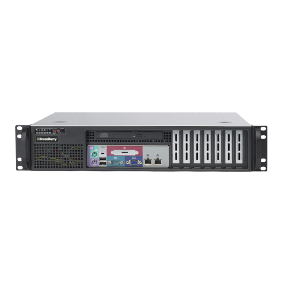
- Page 2 This product, including software and documentation, is the property of Supermicro and/or its licensors, and is supplied only under a Supermicro’s SC523 chassis features easy-access front I/O ports and a depth of license.
- Page 3 SC523 Chassis Manual Preface Manual Organization Notes Chapter 1 Introduction The first chapter provides a description of the main components included with this chassis and describes the primary features of the SC523 chassis. This chapter also includes contact information. Chapter 2 System Safety This chapter lists warnings, precautions, and system safety.
-
Page 4: Table Of Contents
Removing and Installing Hard Drives ............. 5-4 Part Numbers ....................1-1 Removing and Installing the DVD or CD-ROM ..........5-7 Contacting Supermicro ..................1-2 Installing the Motherboard ................5-8 Chapter 2 Standardized Warning Statements for AC/DC Systems Installing the I/O Shield ................... 5-8 About Standardized Warning Statements ............ - Page 5 SC523 Chassis Manual Appendix A SC523 Power Supply Specifications viii...
-
Page 6: Overview
Two fixed 3.5" drives offer maximum storage capacity in a 2U short-depth form factor. Shipping List Part Numbers Please visit the Supermicro website for the latest shipping lists and part numbers for your particular chassis model at www.supermicro.com. SC523L-410B Chassis Model... -
Page 7: Contacting Supermicro
Super Micro Computer, Inc. 980 Rock Ave. San Jose, CA 95131 U.S.A. Tel: +1 (408) 503-8000 Fax: +1 (408) 503-8008 Email: marketing@supermicro.com (General Information) support@supermicro.com (Technical Support) Website: www.supermicro.com Europe Address: Super Micro Computer B.V. Het Sterrenbeeld 28, 5215 ML... -
Page 8: Chapter 2 Standardized Warning Statements For Ac/Dc Systems
Only certified technicians should attempt to install or configure components. Read this appendix in its entirety before installing or configuring components in the Supermicro chassis. These warnings may also be found on our web site at http://www.supermicro.com/ about/policies/safety_information.cfm. Warning Definition Warning! This warning symbol means danger. - Page 9 SC523 User's Manual Warning Statements for AC Systems Warnung جسذٌة اصابة ًتتسبب ف حالة ٌوكي أى ًاًك ف خطز ًٌٌع هذا الزهز !تحذٌز WICHTIGE SICHERHEITSHINWEISE الذوائز بالوخاطز الٌاجوة عي ي على علن ، ك هعذات تعول على أي قبل أى Dieses Warnsymbol bedeutet Gefahr.
-
Page 10: Installation Instructions
SC523 User's Manual Chapter 2: Warning Statements for AC/DC Systems Installation Instructions Circuit Breaker Warning! Warning! This product relies on the building's installation for short-circuit (overcurrent) Read the installation instructions before connecting the system to the power source. protection. Ensure that the protective device is rated not greater than: 60VDC, 20 A. 設置手順書... -
Page 11: Power Disconnection Warning
SC523 User's Manual Chapter 2: Warning Statements for AC/DC Systems ¡Advertencia! 경고! El sistema debe ser disconnected de todas las fuentes de energía y del cable 이 제품은 전원의 단락(과전류)방지에 대해서 전적으로 건물의 관련 설비에 eléctrico quitado de los módulos de fuente de alimentación antes de tener acceso 의존합니다. -
Page 12: Equipment Installation
SC523 User's Manual Chapter 2: Warning Statements for AC/DC Systems Equipment Installation Waarschuwing Deze apparatuur mag alleen worden geïnstalleerd, vervangen of hersteld door Warning! geschoold en gekwalificeerd personeel. Only trained and qualified personnel should be allowed to install, replace, or service Restricted Area this equipment. -
Page 13: Battery Handling
SC523 User's Manual Chapter 2: Warning Statements for AC/DC Systems Warnung אזור עם גישה מוגבלת Bei Einsetzen einer falschen Batterie besteht Explosionsgefahr. Ersetzen Sie die Batterie nur durch den gleichen oder vom Hersteller empfohlenen Batterietyp. !אזהרה Entsorgen Sie die benutzten Batterien nach den Anweisungen des Herstellers. יש... -
Page 14: Redundant Power Supplies
SC523 User's Manual Chapter 2: Warning Statements for AC/DC Systems Redundant Power Supplies امداد الطاقة بوحدات عدة اتصاالت جهاز ال يكون لهذا قد الكهرباء عن وحدة ال لعسل كافة االتصاالت يجب إزالة 경고! Warning! This unit might have more than one power supply connection. All connections must 이... -
Page 15: Comply With Local And National Electrical Codes
SC523 User's Manual Chapter 2: Warning Statements for AC/DC Systems Attention מתח בפנל האחורי L'équipement doit être installé conformément aux normes électriques nationales et locales. !הרה אז קיימת סכנת מתח בפנל האחורי בזמן תפעול המערכת. יש להיזהר במהלך תיאום חוקי החשמל הארצי .העבודה... -
Page 16: Hot Swap Fan Warning
SC523 User's Manual Chapter 2: Warning Statements for AC/DC Systems ¡Advertencia! 警告 當您從機架移除風扇裝置,風扇可能仍在轉動。小心不要將手指、螺絲起子和其他 Al deshacerse por completo de este producto debe seguir todas las leyes y 物品太靠近風扇。 reglamentos nacionales. Warnung Attention Die Lüfter drehen sich u. U. noch, wenn die Lüfterbaugruppe aus dem Chassis La mise au rebut ou le recyclage de ce produit sont généralement soumis à... -
Page 17: Dc Power Supply
SC523 User's Manual Chapter 2: Warning Statements for AC/DC Systems DC Power Supply Attention Quand des fils torsadés sont nécessaires, utiliser des douilles terminales homologuées telles que celles à circuit fermé ou du type à plage ouverte avec Warning! cosses rebroussées. Ces douilles terminales doivent être de la taille qui convient When stranded wiring is required, use approved wiring terminations, such as aux fils et doivent être refermées sur la gaine isolante et sur le conducteur. -
Page 18: Dc Power Disconnection
SC523 User's Manual Chapter 2: Warning Statements for AC/DC Systems DC Power Disconnection 주의! Warning! 다음 절차들을 수행하기 전에, 전원이 DC회로로부터 제거되었는지를 확인해 Before performing any of the following procedures, ensure that power is removed 주십시오. from the DC circuit. 警告... - Page 19 SC523 User's Manual ¡Advertencia! Puede haber energía o voltaje peligrosos en los terminales eléctricos de CC. Reemplace siempre la cubierta cuando no estén utilizándose los terminales. Asegúrese de que no haya acceso a conductores descubiertos cuando la cubierta esté colocada. Attention Le voltage ou l'énergie électrique des terminaux à...
-
Page 20: Chapter 3 Chassis Components
Components Chassis The chassis includes one slim DVD dummy cover, and two 3.5" fixed hard drives. For the latest shipping lists, visit our website at: www.supermicro.com. Fans The SC523 chassis accepts two system fans. System fans for the SC523 chassis are powered from the serverboard. -
Page 21: Air Shroud
Supermicro Authorized Distributors/ System Integrators/Resellers. A list of Supermicro Authorized Distributors/System Integrators/Reseller can be found at: http://www.supermicro.com. Click the Where to Buy link... -
Page 22: Chapter 4 System Interface
Chapter 4: System Interface Chapter 4 System Interface Overview This chasis includes LEDs on the control panel and drive carriers that indicate the activity and health of specific components. Control Panel Buttons There are two buttons located on the front of the chassis: a reset button and a power on/off button. -
Page 23: Control Panel Leds
SC523 Chassis Manual Chapter 4: System Interface 3. Verify that the heatsinks are installed properly. 4. If the chassis cover is not aligned correctly, the airflow may be disrupted. This leads to overheating. Confirm that the chassis cover is placed correctly. Reset: The reset button is used to reboot the system. - Page 24 SC523 Chassis Manual Notes...
-
Page 25: Chapter 5 Chassis Setup And Maintenance
Chapter 5: Chassis Setup and Maintenance Chapter 5 Chassis Setup and Maintenance Overview This chapter covers the steps required to install components and perform mainte- nance on the chassis. The only tools needed to install components and perform maintenance is a Phillips screwdriver and under certain circumstances, a hex wrench. -
Page 26: Removing The Chassis Cover
SC523 Chassis Manual Chapter 5: Chassis Setup and Maintenance Removing the Chassis Cover Removing and Installing the Air Shroud Air Shroud Perforated Tabs Figure 5-2. Removing the Air Shroud Air shrouds concentrate airflow to maximize fan efficiency. The SC523 chassis air shroud does not require screws to set it up. -
Page 27: Removing And Installing Hard Drives
SC523 Chassis Manual Chapter 5: Chassis Setup and Maintenance Removing and Installing Hard Drives Hard Drives Figure 5-4. Removing the Hard Drive Tray from the Chassis Figure 5-3. Locating the Fixed Hard Drives within the Chassis Removing the Hard Drives and Hard Drive Trays from the Chassis 5. -
Page 28: Removing And Installing The Dvd Or Cd-Rom
1. Carefully slide the DVD or CD-ROM and comport tray into the opening in the 5. Reconnect the wiring to the hard drive. front of the chassis. Warning: Only enterprise level hard drives are recommended for use in 2. Secure the drive with the screws previously set aside and reattach the wiring. Supermicro chassis. -
Page 29: Installing The Motherboard
SC523 Chassis Manual Chapter 5: Chassis Setup and Maintenance Flat head Round head Pan head Round head 6-32 x 5 mm 2.6 x 5 mm 3 x 5 mm 6-32 x 5 mm Installing the Motherboard Permanent and Optional Standoffs [0.197] [0.197] [0.197]... - Page 30 SC523 Chassis Manual Chapter 5: Chassis Setup and Maintenance PCI Slot Setup PCI Slot Cover Expansion Card Slots Figure 5-10. Remove the Expansion Card Slot Screw SC523 chassis include seven PCI slots for expansion cards. Installing Expansion Cards: Figure 5-9. Installing the Motherboard 1.
-
Page 31: Checking The Airflow In The System
SC523 Chassis Manual Chapter 5: Chassis Setup and Maintenance Checking the Airflow in the System Proper airflow allows the chassis to keep the server components cooled and prevent damage. Use the following steps to check the airflow after setting up the system or servicing. -
Page 32: System Fans
Power Supply Replacement SC523L-520B or SC523L-410B The SC523L-520B and SC523L-410B chassis models include one power supply. Replacement units can be ordered directly from Supermicro (see contact informa- tion in the Preface). Removing the Power Supply 1. Power down the system and remove the power cord as described in Section 5-2 and remove the cover as described in Section 5-3. - Page 33 SC523 Chassis Manual Chapter 5: Chassis Setup and Maintenance Power Supply Power Supply Bracket Screws Bracket Screws Power Supply Power Supply Mounting Screws Mounting Screws Bracket Bracket Figure 5-15. Removing the Power Supply Figure 5-14. Removing the Power Supply 4. Remove the mounting screws holding the power supply to the floor of the chassis and set them aside for later use.
-
Page 34: Power Supply Replacement Sc523L-505B
Chapter 5: Chassis Setup and Maintenance Power Supply Replacement SC523L-505B The SC523L-505B chassis model includes one power supply. Replacement units can be ordered directly from Supermicro (see contact information in the Preface). Power Supply Bracket Screws Removing the Power Supply 1. - Page 35 SC523 Chassis Manual Power Supply Bracket Screws Mounting Screws Power Supply Bracket Figure 5-15. Removing the Power Supply Installing the Power Supply 1. Place the power supply bracket on the rear of the power supply 2. Use the power supply bracket screws previously set aside to attach the power supply bracket to the rear of the power supply.
-
Page 36: Chapter 6 Rack Installation
Chapter 6: Rack Installation Chapter 6 Rack Installation Overview This chapter provides instructions for mounting the SC523 chassis onto a rack. Unpacking the System You should inspect the box the chassis was shipped in and note if it was damaged in any way. -
Page 37: Rack Precautions
SC523 Chassis Manual Chapter 6: Rack Installation Rack Precautions Rack Mounting Considerations • Ensure that the leveling jacks on the bottom of the rack are fully extended to the floor with the full weight of the rack resting on them. Ambient Operating Temperature If installed in a closed or multi-unit rack assembly, the ambient operating tempera- •... -
Page 38: Rack Mounting Instructions
SC523 Chassis Manual Chapter 6: Rack Installation Rack Mounting Instructions This section provides information on installing the SC523 chassis into a rack unit with the rails provided. There are a variety of rack units on the market, which may mean the assembly procedure will differ slightly. You should also refer to the instal- lation instructions that came with the rack unit you are using. -
Page 39: Installing The Chassis Into A Rack
SC523 Chassis Manual Chapter 6: Rack Installation Outer Rails Rail Brackets Figure 6-3. Rack Brackets Installing the Outer Rails to the Rack 1. Confirm that the inner rails have been separated from the outer rails. 2. Locate the rail brackets in the accessories box. The chassis package includes four rail brackets and two chassis mounts. -
Page 40: Installing The Server Into A Telco Rack
SC523 Chassis Manual Chapter 6: Rack Installation L-Brackets L-Brackets Figure 6-6. Mounting the Chassis onto an Open (Telco) Rack Installing the Server into a Telco Rack Installing the chassis into a Telco type rack 1. Use two L-brackets on either side of the chassis (four total). Determine how far the server will extend out the front of the rack. - Page 41 SC523 Chassis Manual Notes 6-10...
- Page 42 Appendix A: Power Supply Specifications Appendix A SC523 Power Supply Specifications This appendix lists power supply specifications for your chassis system. SC523L-410B 410W MFR Part # PWS-0061 Voltage Range: -36 to -72V Nominal Voltage: -.48V Rated DC Voltage Max Input Current: 18A @ -48V 9.5 - 4.5 Amp DC Output 5V + 3.3V ≤...
- Page 43 SC523 Chassis Manual SC523L-520B 520W MFR Part # PWS-521-1H 100 to 240V AC Voltage 50-60 Hz 7-3 Amp 20 Amp +5V standby 3 Amp +12V 39 Amp 0.5 Amp -12V 16 Amp +3.3V...
Need help?
Do you have a question about the SC523 Series and is the answer not in the manual?
Questions and answers