Table of Contents
Advertisement
Quick Links
Проконсультироваться и купить данное оборудование вы можете в компании «АНД-Системс»
адрес: 125480, г.Москва, ул.Туристская, д.33/1; site: https://andpro.ru тел: +7 (495) 545-4870 email: info@andpro.ru
S
При обращении используйте промокод AND-PDF и получите скидку.
UPER
®
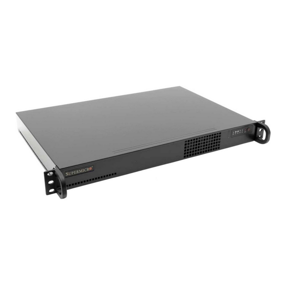
SC510 Chassis Series
SC510-200B
SC510L-200B
SC510T-200B
SC510-203B
SC510T-203B
USER'S MANUAL
1.0c
Advertisement
Table of Contents


Need help?
Do you have a question about the SC510-200B and is the answer not in the manual?
Questions and answers