Advertisement
Advertisement
Table of Contents

Related Manuals for Mac allister MJ10250XI


Summary of Contents for Mac allister MJ10250XI
-
Page 2: Safety Instructions
SAFETY INSTRUCTIONS WARNING! When using electric tools basic safety precautions should always be followed to reduce the risk of fire, electric shock and personal injury including the following. Read all these instructions before attempting to operate this product and save these instructions. - Page 3 hand. 13. Do not overreach. - Keep proper footing and balance at all times. 14. Maintain tools with care. - Keep cutting tools sharp and clean for better and safer performance. - Follow instruction for lubricating and changing accessories. - Inspect tool cords periodically and if damaged have them repaired by an authorized service facility.
- Page 4 – for tools provided with an isolating transformer: Never use the tool without the transformer delivered with the tool or of the type as specified in these instructions. – Replacement of the plug or the supply cord shall always be carried out by the manufacturer of the tool or his service organisation.
- Page 5 - Remove wrenches, cut-off pieces, etc. from the table before the switch is turned on. - NEVER wear gloves during operation. - Keep hands out of the line of the saw blade. - NEVER stand or permit anyone else to stand in line with the path of the saw blade. - Make sure the blade is not contacting the riving knife or workpiece before the switch is turned on.
- Page 6 - Always use clean, sharp, and properly set blades. Never make cuts with dull blades. - To avoid pinching the blade, support the work properly before beginning a cut. - When making a cut, use steady, even pressure. Never force cuts. - Do not cut wet or warped lumber.
- Page 7 all parts of the operating cycle such as the times when the tool is switched off and when it is running idle in addition to the trigger time).Note The use of other tools will reduce the users’ total working period on this tool. Helping to minimise your vibration exposure risk.
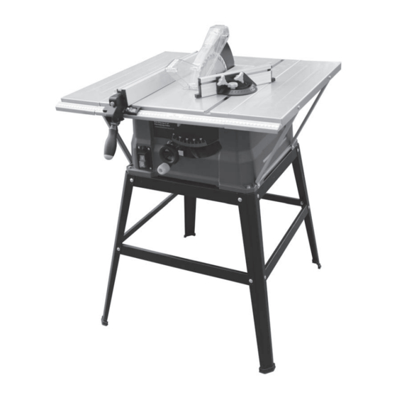
- Page 8 1. Push stick hold 11. Blade 2. Stand 12. Miter gauge 3. On/Off switch 13. Right extension table 4. Overload reset switch 14. Bevel-locking handle 5. Rip fence locking handle 15. Bevel adjusting handwheel 6. Working table 16. Height adjustment knob 7.
-
Page 9: Technical Data
TECHNICAL DATA Volts: 220V~50Hz Power Input: 1500W No load speed: 4500min Blade size: Ø254x2.8xØ15.9mm Max cutting capacity: 85mm (90°) / 60mm (45°) Table size: 430x638mm Blade tilting range: 0- 45 Weight: 24.6kg... - Page 10 Warning: Before using your table saw, read the instruction manual carefully. Stand legs (4pcs) Warning: Carefully remove the table saw from the carton and remove the protective polyfoam from around the long top leg brackets (2pcs) motor. Warning: Do not connect to the power Short top leg brackets (2pcs) supply before assembly, adjustment and maintenance.
- Page 11 - Insert the rubber foot (6) into the bottom of each leg. (Fig. 5) - Place the stand on a level surface, and adjust it so that all of the legs are contacting the floor and are at similar angles to the floor. Tighten all of the screws.
- Page 12 NOTE: One hole (1) on the extension table must be in the front after finished. - Attach two supporting bars with the extension table with flat washers 6, spring washers 6, hex nuts M6 and hex bolts M6 x 16. Position the other end of bars to cabinet with flat washers 6, hex nuts 6 and hex bolts M6 x 16.
- Page 13 5. To assemble the push stick hold (Fig. 14) There is a push stick hold on the left side of the machine. You can connect the push stick hold Push stick hold (2pcs) with four screws supplied and you can put the push stick on the hold when you do not use it.
- Page 14 7. To assemble the blade gurad (Fig. 17-18) WARNING: The saw blade guard must be in position at all times to prevent contact with the blade. It should lift up and onto the workpiece when the workpiece is passed through the saw. - Attach the blade guard over the riving knife so that the hole in the guard and the hole in the riving knife are aligned.
- Page 15 9. To use dust extraction port (Fig. 22) WARNING: To prevent fire hazard, clean and remove sawdust from under the saw frequently. - To prevent sawdust buildup inside the saw housing, for best result, attach a vacumm hose (not included) to the dust extraction port. DO NOT operate the saw with hose in place unless the vacuum is turned on.
-
Page 16: Operation Controls
OPERATION CONTROLS 1. On-Off safety switch (Fig. 23) WARNING: Before turning on the switch make sure the blade guard is correctly installed and Operating properly. To start the machine push the switch (1) to the ON position. (See Fig. 23) When turning the switch ON stand on either side of the blade and never in front of it. - Page 17 5. Bevel-locking handle (Fig. 24) The bevel-locking handle (3) locks the blade in the desired tilting angle. To loosen turn it anti-clockwise. When setting the angle of the cut fully loosen it. Before turning the table saw ON, be sure it is securely tightened so that the blade will not shift during the table saw operation.
-
Page 18: Basic Table Saw Operations
BASIC TABLE SAW OPERATIONS For safety reasons, verify that the operator has read the section entitled general safety guidelines for the table saw before operating this saw. Verify the following before every time the table saw is used: - The blade is tight. - The blade bevel lock knob is locked. - Page 19 the work piece is between the blade and the fence. Keep the work piece approximately 1” (2.5 cm) away from the blade. - Turn the saw ON, and wait for the blade to reach full speed. - Slowly feed the work piece into the blade by pushing forward on the section of the work piece that will pass between the blade and the fence.
- Page 20 - Raise the blade until it is approximately 1/8” (3.2 mm) above the top of the work piece. - Hold the work piece firmly against the miter gauge, with the path of the blade in line with the desired cutting line. Move the work piece to within 1”...
- Page 21 - Set the miter gauge to the desired miter angle, and secure it in position by tightening the miter gauge locking handle. - Hold the work piece firmly against the face of the miter gauge throughout the cutting operation.
- Page 22 ADJUSTMENT 90° Set screw 90° Set screw 1. Adjusting the bevel stops (Fig. 32-34) This saw has positive stops that will quickly 45° Set screw 45° Set screw position the saw blade at 90° or 45° to the table. The angle settings of the saw have been set at the factory and, unless damaged in shipping, should not require setting during assembly.
-
Page 23: Maintenance
MAINTENANCE Always disconnect the device before performing any adjustment or maintenance operation. If the supply cord is damaged, it must be replaced by the manufacturer or its service agent in order to avoid a hazard. Disconnect from the power supply immediately if the supply cord is damaged. - Page 24 CAUTION: If one of these parts: blade guard / blade / table insert is damaged, you can replace yourself. 5. To replace the blade (Fig.15, 18, 35-36) When you need replace the saw blade, please follow the procedure as belowing: - Unplug the saw.
-
Page 25: Exploded View
EXPLODED VIEW... -
Page 27: Part Lists
PART LISTS Description Description Hex bolt Riving knife Big flat washer Bolt Hex nut Right extension table Screw Stopper B Stand leg Guide tube Flat washer Bolt Spring washer holder Bracket A Screw Bracket B Pointer Rubber foot Compress spring Bracket D Screw B Bracket C... - Page 28 Description Description Saw blade Anti-bending jacket Closure plate A Plug wires Liner Screw Inner flange Switch box assembly Bolt Capacitance Screw Overload protection Spring washer Switch box cover Flat washer Tight line Screw Screw Rotating plate B Shaft Collar Friction plate Bevel gear Holder A Position block...
- Page 29 Description Description Comfort Cover Bearing Screw Rotor assembly Blade wrench A Screw Blade wrench B Stator Push stick hold Bearing Screw Damping ring Push stick Case Screw Brush holder Big flat washer Brush Vane Gap film Electrical motor Holder A Crimping board Screw Screw...
Need help?
Do you have a question about the MJ10250XI and is the answer not in the manual?
Questions and answers