Table of Contents
Advertisement
Advertisement
Table of Contents

Related Manuals for AVMATRIX PVS0605


Summary of Contents for AVMATRIX PVS0605
- Page 1 VIDEO SWITCHER PVS0605 User Manual VER 0.1...
-
Page 2: Table Of Contents
Contents 1.Brief Introduction .............................1 1.1 Overview ..............................1 1.2 Main Features ............................1 2. Connections ..............................2 2.1 Interfaces ..............................2 2.2 Specification .............................3 3. Control Panel ..............................5 3.1 Description ...............................5 3.2 Keyboard Button ............................6 4. Operation Instruction .............................9 4.1 Multiview Output Layout .........................9 4.2 T-Bar Calibration .......................... -
Page 3: Brief Introduction
1.Brief Introduction 1.1 Overview The video switcher is an all-in-one 6-channel video switcher that allows video switching, audio mixing, and video recording. 1.2 Main Features 6 channel inputs: 4xSDI and 2xDVI-I/HDMI/VGA/USB player inputs ⚫ ⚫ 2xSDI & 1xHDMI PGM outputs, 1xSDI AUX output, 1xSDI & 1xHDMI multiview outputs ⚫... -
Page 4: Connections
2. Connections 2.1 Interfaces Power Switch 1×SDI AUX Output 12V DC Power Input 2×SDI PGM Outputs 12V DC Power Output 4×SDI Inputs RS422 for Camera Remote Control 2×DVI-I(VGA) Input RJ45 For Sync Time & Firmware Upgrade 2×HDMI Input XLR Balanced Audio(L/R) Input 1×SD Slot for Record... -
Page 5: Specification
2.2 Specification Video Inputs SDI×4, HDMI/DVI-I/VGA/USB×2 Bit Rate 270Mbps~3Gbps Return Loss >15dB, 5MHz~3GHz Signal Amplitude 800mV±10% (SDI/HDMI/DVI/VGA) Impedance 75Ω (SDI/VGA), 100Ω (HDMI/DVI) 1080p 60/59.94/50/30/29.97/25/24/23.98 1080psF 30/29.97/25/24/23.98 SDI Input Format 1080i 60/59.94/50 720p 60/59.94/50/30/29.97/25/24/23.98 625i 50 PAL, 525i 59.94 NTSC 4K 60/50/30, 2K 60/50/30 1080p 60/59.94/50/30/29.97/25/24/23.98/23.976... - Page 6 PGM Outputs 2×HD/3G-SDI; 1×HDMI Type A AUX Output 1×HD/3G-SDI 1080p 50/60/30/25/24 PGM Output Format 1080i 50/60 Multiview Output 1×HD/3G-SDI; 1×HDMI Type A Outputs Multiview Output Format 1080p 60 Return Loss >15dB 5MHz~3GHz Signal Amplitude 800mV±10% (SDI/HDMI/DVI-I/VGA) Impedance SDI: 75Ω; HDMI: 100Ω...
-
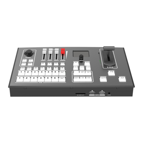
Page 7: Control Panel
3. Control Panel 3.1 Description Camera Control Audio Mixer Menu Control and Display T-bar Manual Transition Auto, Cut, FTB Transition Effects, MIX, WIPE, DP Luma Key, Chroma Key, PIP, POP, SHIFT USB Media Player Control Program Row Preview Row... -
Page 8: Keyboard Button
3.2 Keyboard Button Camera Control ◼ CAM1 and CAM2 buttons are for Camera 1, Camera 2. ZOOM IN and ZOOM OUT to adjust the size of the picture. Press the button, the button LED will be turned on to indicate that the manual mode is enabled. - Page 9 ◼ PGM PVW Channel Selection PGM row is for selecting the signal source for program. Selected PGM button turns on the red LED. PVW row is for selecting the signal source for preview. Selected PVW button will turns on the Green LED.
- Page 10 ◼ Chroma Key In a chroma key two images are combined using a special technique and a color from one image is removed, revealing another image behind it. Chroma key is commonly used for weather broadcasts, where the meteorologist appears to be standing in front of a large map.
-
Page 11: Operation Instruction
4. Operation Instruction 4.1 Multiview Output Layout 1) PGM and PVW as Preview and Program displayed as following image. The level meter of PGM audio is shown only in multiview. SDI/HDMI PGM out is without any overlays. 2) The following 6 windows come from the 6 input signals. The signal source of window 5 and 6 can be selected from HDMI, DVI, VGA, USB. -
Page 12: T-Bar Calibration
4.2 T-Bar Calibration The T-Bar of the video switcher may happen to misalignment, when the origin of the coordinates offset the T-Bar calibration is necessary before using. 1) Power off the video switcher and press button 1 and 2 of PVW at same time. KEEP pressing the buttons until all calibration process finish. -
Page 13: Transition Control
The selected PGM source will circled in red border, while the selected PVW source will be circled in green border. For example, switching the PGM source to SDI 1 and PVW source to SDI 2. The button selection as below image. -
Page 14: Ftb (Fade To Black)
4.3.3 FTB (Fade to Black) Press FTB button it will fade the current video Program source to black. The button will flash to indicate that it’s active. When press the button again it acts in reverse from complete black to the currently selected Program video source, and button stop flashing. -
Page 15: Transition Effects
2) Video Format Supporting MPEG4(Divx), MPEG4(Xvid), AVC(H264), MPEG4(Divx), AVC(H264), FLV1 HEVC(H265) MPEG4(Divx), MPEG4(Xvid), AVC(H264), MPEG4(Divx), MPEG4(Xvid), AVC(H264), HEVC(H265), MPEG2 HEVC(H265) MPEG1 MPEG4(Divx), AVC(H264), HEVC(H265) 3) Image format support: BMP, JPEG, PNG. 4.4 Transition Effects 4.4.1 MIX Transition Pressing the MIX button selects a basic A/B Dissolve for the next transition. -
Page 16: Pip And Pop
4.5 PIP and POP When the T-Bar located at B-BUS to active the PIP/POP, there will be a small image display on the top left corner of the PVW window as following image: Press button 1-6 from PVW row to switch the video source of PIP/POP. -
Page 17: Chroma Key
4.6 Chroma Key Turn on the Chroma Key, a color from the key source will be removed, revealing another background image behind it. Chroma Key is usually used for virtual studio, such as weather broadcasts, where the meteorologist appears to be standing in front of a large map. In the studio the presenter is standing in front of a blue or green background. -
Page 18: Camera Remote Control
When turn on the Luma Key, all the black areas defined by the luminance in the video signal will be made transparent so that the background can be revealed underneath. Therefore, the final composition does not retain any black from the graphic because all the black parts have been cut out of the image. This function is often used for subtitle overlay of virtual studio. -
Page 19: Main Menu Settings
6. Main Menu Settings When STATUS menu is not selected, press the MENU button to go to main menu directly. In case one of the items is selected (see below), rotate the MENU button rotate anticlockwise to exit the choice, then press the MENU button to go to the main menu. -
Page 20: System Settings
2) Following Mode After that the video switcher will remember your last choice. Press Master button to enable the following mode audio control. When the audio is in Following mode the audio is coming from the embedded audio of Program video source. Adjust the master fader to control the audio volume. -
Page 21: Language
Access to system settings from the menu to switch the real-time clock shown in Analog or Digital. 6.3.3 Clock Time Setting Connect video switcher to a PC and download a time control software from AVMATRIX official website www.avmatrix.net/download/ Open the software and click Scan to search and connect the device, then the clock time will be changed to same time to the PC’s time. -
Page 22: Sd Card Install And Uninstall
6.5.2 SD Card Install and Uninstall 1. Install SD card: First, format SD card to exFAT/ FAT32 file system format. Install Plug and press the SD card into the slot from the side of video switcher. Wait 3 sec, the LED indicator beside it will turn on.
Need help?
Do you have a question about the PVS0605 and is the answer not in the manual?
Questions and answers