
Subscribe to Our Youtube Channel
Related Manuals for Bentone B30A RME


Summary of Contents for Bentone B30A RME
- Page 1 178 080 51 2015-03–11 Providing sustainable energy solutions worldwide Installation- and maintenance instruction B30A RME, B40A RME...
-
Page 3: Table Of Contents
OIL BURNER CONTROL: LOA21... / LOA24... ____ NOZZLE TABLE ___________________________________________________ FAULT LOCATION _______________________________________________ Burner will not start __________________________________________ Burner will not start after normal use __________________ Delayed ignition, burner starts; pulsation _____________ 10. DECLARATION OF CONFORMITY ____________________ Bentone B30A RME, B40A RME... -
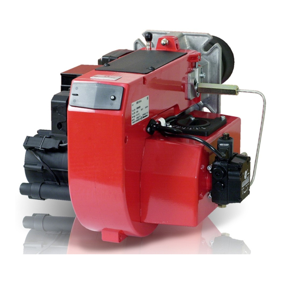
Page 4: Description
14. Blast tube Ignition cable 15. Air adjustment Ignition transformer 16. Air damper 17. Solenoid valve on connection hose Photo cell Control box 18. Air intake Reset button 19. Pump 10. Cover, inspection glass 20. Connection hose Bentone B30A RME, B40A RME... -
Page 5: Technical Data
2. TECHNICAL DATA Dimensions B30A Dimensions B40A Burner tube B30 Length of burner tube Measure B Standard Burner tube B40 Standard Flange measure ø 108 160-190 ø 114 200-230 Bentone B30A RME, B40A RME... -
Page 6: Output Range And Nozzles Recommended
1,0-2,0 2,5-3,5 Note that the spray angle and the spray pattern change with the pump pressure. 7,0-9,0 Bentone B30A RME, B40A RME... -
Page 7: General Instructions
Then the volume of air is reduced until soot occurs and increased again to reach a combustion free of soot. By this procedure an optimum adjustment is obtained. If larger nozzles are used the preadjustment of both the air volume and the nozzle assembly must be increased. Bentone B30A RME, B40A RME... - Page 8 The oil pipe and electric cable should be fitted so that the burner can be placed on the floor for inspection of the combustion device. Oil hoses must be of a quality designed for FAME (RME). Bentone B30A RME, B40A RME...
- Page 9 Lock the screw B again. Air adjustment 0-10 Loosen the stop screw B and turn the knob along the scale to the desired position and tighten the screw. Check the air adjustment by making a flue gas analysis. Bentone B30A RME, B40A RME...
-
Page 10: Maintenance Of Oil Burner B30
Service of burner head Open the cover plate and remove the connection hose by undoing screw A. Loosen or swing out the burner from the boiler. Turn the blast tube to the left and withdraw it. Bentone B30A RME, B40A RME... -
Page 11: Maintenance Of Oil Burner B40
Service of burner head Open the cover plate and remove the connection hose by undoing screw A. Loosen or swing out the burner from the boiler. Loosen 2 fixing screws and withdraw the blast tube. Bentone B30A RME, B40A RME... -
Page 12: Oil Circuit Diagram
6. OIL CIRCUIT DIAGRAM Nozzle Safety valve Oil pump Bentone B30A RME, B40A RME... -
Page 13: Electric Equipment
* If there is no plug-in contact (X2) on the boiler, connect to the contact enclosed. In case the twin thermostat is in series on incoming phase L1, a loop between the terminals T1 and T2 is necessary. Bentone B30A RME, B40A RME... - Page 14 Max. photo current at start: 5µ A Enclosure: IP 40 Control of photo current Current through photo unit is measured with a d.c. ammeter (a moving coil instrument connected in series with the photo unit). Bentone B30A RME, B40A RME...
-
Page 15: Nozzle Table
- Design of nozzle - Capacity (high capacity - small difference) - Expect the output from the burner to reduce by 10–20% when fuelled by FAME (RME) due to the lower energy content of the oil. Bentone B30A RME, B40A RME... - Page 16 - Design of nozzle - Capacity (high capacity - small difference) - Expect the output from the burner to reduce by 10–20% when fuelled by FAME (RME) due to the lower energy content of the oil. Bentone B30A RME, B40A RME...
-
Page 17: Fault Location
Delayed ignition Check ignition electrodes Too strong a draught not damaged Too great a pressure drop at brake plate Check high voltage wiring Check position of nozzle assembly adjustment Correct the boiler draught Adjust the burner Bentone B30A RME, B40A RME... -
Page 18: Declaration Of Conformity
In that the burner conforms to the above mentioned standards it is awarded the CE mark. Indem der Brenner die obengenannten Normen und Richtlinien erfüllt, erhält der Brenner die CE-Kennzeichnung. Du fait de leur conformité aux directives mentionnées ci-dessus, les brûleurs Bentone bénéfi cient du marquage CE. Enertech AB, Bentone Division/ Ljungby, Sweden, 150227 (27/02/15) är kvalitetscertifi erat enligt/... - Page 19 OIL BURNERS MAINTENANCE INSTRUCTIONS General information If the burner starts but does not ignite Make an attempt to start the burner. Keep the boiler room clean. Ensure that the boiler room has permanent fresh air intake. Switch off before Never make close repeated start attempts. dismantling the oil burner.
- Page 20 Enertech AB. P.O Box 309, SE-341 26 Ljungby. www.bentone.se, www.bentone.com...
Need help?
Do you have a question about the B30A RME and is the answer not in the manual?
Questions and answers