Bentone BG 700 Installation And Maintenance Instruction
Hide thumbs
Also See for BG 700:
- Installation and maintenance instruction (148 pages) ,
- Manual (25 pages) ,
- Installation and maintenance instruction (52 pages)

Related Manuals for Bentone BG 700


Summary of Contents for Bentone BG 700
- Page 1 178 006 85-2 2016-11-21 Providing sustainable energy solutions worldwide Installation- and maintenance instruction BG 700/800/950...
-
Page 3: Table Of Contents
5.3 Funktion LFL1... _____________________________________________________ 5.4 Control programme under fault conditions and lockout indication LFL1..____________________________________________ 6. Measures and checks before start-up ________________________________________________________ 6.1 2-Stage or modulating burners ________________________________ 6.2 Gas nozzle BG 700/800 __________________________________________ 6.3 Gas nozzle BG 950 ________________________________________________ Bentone BG700M,800M,950M... -
Page 4: General
• It is not permitted to use the burner outside the intended area of use. • The burner may not be commissioned with safety or protective devices that are not it for purpose. Nor are custom design modiications or the installation of accessories not tested together with the Bentone BG700M,800M,950M... - Page 5 Ensure that local rules and regulations are observed. • Separate boiler rooms and fuel stores immediately next to a separate boiler room should be designed as individual ire compartments. Ensure that local rules and regulations are observed. Bentone BG700M,800M,950M...
-
Page 6: Safety Instructions
• Make sure everything is delivered and the goods have not been damaged during transit. • If something is wrong with the delivery, report it to the supplier. • Transport damage must be reported to the shipping company. Bentone BG700M,800M,950M... -
Page 7: Technical Data
1. Technical data Dimensions Length of Flange Burner tube Burner tube Type burner tube measure A measure B measure C Standard BG 700 Long design Standard BG 800 Long design Standard 1 Standard 2 BG 950 Standard 3 *730 *970 BG 700... -
Page 8: Capacity Range
Gas quantity Gas quantity Max. Nominal of gas at min. power at max. connection connection power Nm pressure pressure mbar mbar BG 700 300–1500 BG 700 360–1500 187,5 100–360 BG 700 380–1650 14,6 BG 800 380–2400 BG 800 380–2400 47,5 BG 800 380–2400... - Page 9 General BG 700 G20, G21 300-1500 kW 380-1650 1000 1200 1400 1600 BG 800 380-2400 kW 1000 1200 1400 1600 1800 2000 2200 2400 BG 950 mbar 500-3200 kW 1400 1900 2400 2900 3400 Bentone BG700M,800M,950M...
-
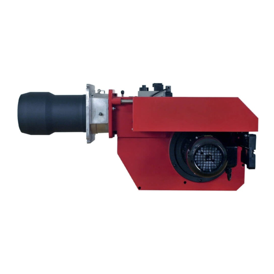
Page 10: Description Bg 700/800/950
General 1.2 Description BG 700/800/950 Bentone BG700M,800M,950M... - Page 11 Time meter (optional) Ignition electrode Nozzle Contactor with thermal overload protection Ionisation electrode Control box Motor Filter Connection gas ittings MultiBloc Connection lange Ignition transformer Air damper Impulse line ire room Air damper motor 29. Ball valve Air pressure switch Bentone BG700M,800M,950M...
-
Page 12: General Instruktions
Adjust the burner to appr. 20% excess air in accordance with the table. Check the lue gas temperature. Calculate the eficiency. Check also the actual gas volume on the gas meter so that the correct input is achieved. Bentone BG700M,800M,950M... -
Page 13: Installation
If not, use the connectors included. (Refer to connection under Electric equipment) If an electric connection other than the one recommended by Enertech is used, a risk of damage and injury can arise. Bentone BG700M,800M,950M... -
Page 14: Skeleton Diagrams
General 4. Skeleton diagrams 4.1 Multi-Bloc MB-DLE405-412..B01 Filter couver 1,3,4,6 G 1/8 screw plug Test nipple, optional M4 screwed sealing plug 4.1.1 Electritrical connection MB-DLE405-412..B01 S 20/S 50 When Bio gas is used, Enertech shall always be contacted. Bentone BG700M,800M,950M... - Page 15 Solenoid V1 Solenoid housing Setting: Valve V1 Gas pressure switch - Gas pressure p Connection lange Electrical connection - Main volume Closing spring V1 Valve V2 - Fast stroke Housing Closing spring V2 Hydraulic brake Armature V1 Armature V2 Bentone BG700M,800M,950M...
-
Page 16: 16 4.1.2 Functional Description Of Gas Low
19 at the hydraulic brake under the cover. 4.1.6 Closing function When the supply voltage to the solenoid coils of valves V1 and V2 is interrupted, they are closed within < 1 s by the compression spring Bentone BG700M,800M,950M... -
Page 17: Multi-Bloc Mb-Vef 407-412
M4 screwed sealing plug 7,8,9 G 1/8 female thread for p pulse lines Filter cup 4.3 Multi-bloc MB-VEF 415-420..B01 1, 2, 3, 4, 5 G 1/8 screwed seal plug Test nipple (option) 6, 7, 8 Pulse lines p Bentone BG700M,800M,950M... -
Page 18: Multi-Bloc Mb-Vef425
General 4.4 Multi-Bloc MB-VEF425..B01 1, 2, 3, 4, 5 G 1/8 screwed seal plug Test nipple (option) 6, 7, 8 Pulse lines p MB-VEF 425 B01 4.5 Electritrical connection MB-VEF 407-425 S 10/S 30 Bentone BG700M,800M,950M... -
Page 19: Mounting Of The Burner
The burner is not equipped with a lever that changes the position of the brake plate in the combustion head. On these burners the combustion assembly is designed so that good combustion can be obtained without adjusting the brake plate. Bentone BG700M,800M,950M... -
Page 20: Wiring Diagram Lfl1
General 5.1 Wiring diagram LFL1... Bentone BG700M,800M,950M... -
Page 21: List Of Components Lfl1
Main switch Air pressure switch Main switch If S6 is missing, connection between T6 and T8. Mains connection and fuse in accordance with local regulations. Max loading K1 Connection A1,A2 / 95, 96 / 97, 98 Max 0,2A/15W Bentone BG700M,800M,950M... -
Page 22: Funktion Lfl1
The operation of the burner can now be interrupted by means of the operating switch or the thermostat. The control locks out. The red lamp in the control is lit. Restart the burner by pressing the reset button. Bentone BG700M,800M,950M... -
Page 23: Control Programme Under Fault Conditions And Lockout Indication Lfl1
330V ± 10% test: 380V ± test: 380V ± Short circuit current max. 0,5 mA max. 0,5 mA Min. required ionization current 6 µ A 6 µ A Recommended range of measuring 0...50 µ A 0...50 µ A device Bentone BG700M,800M,950M... -
Page 24: Measures And Checks Before Start-Up
150 mbar. If any leakage, locate the terminal 6 to terminal 7 in the base of LFL1. source by means of soapy water or a leak location spray. After tightening repeat the test. Multibloc Gas train Bentone BG700M,800M,950M... -
Page 25: Gas Nozzle Bg 700/800
General 6.2 Gas nozzle BG 700/800 Natural gas, LPG Natural gas Natural gas, LPG UV-sond 6.3 Gas nozzle BG 950 Natural gas, LPG Distance electrode - brake plate. Bentone BG700M,800M,950M... -
Page 26: Determination Of Gas Volume For The Installation
Temperature of the gas at the gas meter (15°C) Barometer height (945 mbar) Pressure of the gas at the gas meter (15,0 mbar) 273+15 1013,25 945+15 11,1 The gas volume read on the gas meter actually reads1,11 12,9 = 14,4 m Bentone BG700M,800M,950M... -
Page 27: Multi-Bloc, Mb-Vef 420-425
Test point connection G 1/8 downstream of V1, G 1/8 pressure connection for pL blower pressure possible on both sides Setting screw, ratio V Operation display (option) Test point connection G 1/8 downstream of ilter Pulse line possible on both sides Bentone BG700M,800M,950M... -
Page 28: Technical Data
This is especially important when P is concerned. 7.5 Adjustment possibilities ∆ P max. =100 mbar Adjustment range Effective burner pressure ∆ P N=+2 ∆pBr, min =0,5 mbar ∆PL Effective fan pressure N=-2 , max. = 100 mbar ∆ P ∆ P ∆PL Bentone BG700M,800M,950M... -
Page 29: Multi-Bloc, Mbd-Le 405-410
Operation display V1, V2 (optional) Gas low direction Electrical connection for valves Test point connection M4 downstream of valve 2 (DIN EN 175 301-803 connector) Output lange Test point connection G 1/8 downstream of valve 1, possible on both sides Bentone BG700M,800M,950M... -
Page 30: Damper Motor Modulating
• Adjust the gas low with V and check at the same This function facilitates an exchange of damper motor. time the combustion values.. • Go back to min. load and check the combustion value. Adjust if necessary. Bentone BG700M,800M,950M... -
Page 31: General Instructions
Open the ball valve and switch on the main switch. If the burner starts the actual adjustment can be made. Gas quality max. CO lambda 1,2 Natural gas 10,0 11,9 11,5 13,9 Bentone BG700M,800M,950M... -
Page 32: Flame Monitoring And Measurement Of Ionisation Current
Checks should only be made if a fault is suspected. The capacitor, which sould be placed between the terminals on the moving coil instrument, must be of 100 µ F 10-25 V. Control box Flame monitoring Bentone BG700M,800M,950M... -
Page 33: Adjustment Of Air Pressure Switch
Gas pressure switch, air pressure switch rated gas pressure. Decide on pressure at which the gas pressure switch should switch off. Turn the adjustment knob to this value. Tolerance on the scale ±15%. Adjustment range: 2,5-50 mbar GW 50 5-150 mbar GW 150 Bentone BG700M,800M,950M... -
Page 34: Handing Over Of The Installation
• Has the gas control or the motor protector locked out? - Reset. • Is the circulation pump in operation? • Is there a supply of fresh air to the installation? If integral components are of a different make from what is stated in this manual, see the enclosed sheet. Bentone BG700M,800M,950M... -
Page 35: Fault Location Guide
No flame establishment despite a trouble free start The gas solenoid valve defective Replace The gas solenoid valve does not open despite its obtaining voltage Replace coil or the whole valve if necessary. No voltage to the solenoid valve Check the contact Bentone BG700M,800M,950M... - Page 36 The lue gas side is blocked Check the chimney lue. Pulsations during operation The burner is not correctly adjusted Readjust The burner is dirty Clean the burner. Defective chimney Check and change the dimensions if necessary. Bentone BG700M,800M,950M...
- Page 37 Check the burner head and readjust. position Condensation in boiler and chimney The low gas temperature is too low or the quantity of gas is not Increase the lue gas temperature by suficient increasing the gas supply. Insulate the chimney Bentone BG700M,800M,950M...
- Page 38 Do not use naked l ame when inspecting the i re If the burner does not start in spite of repeated room starting attempts call the installer Authorized installer: ____________________________________________________________________________________________________ Address:_____________________________________________________________________________________________ Tel:_________________________________________________________________________________________________ 170 025 05 2015-05-25 Bentone BG700M,800M,950M...
- Page 39 Large l ame Measures Date gas/h Governor Flue gas Ionisa- Pressure Efi ciency temp tion current Fire room Chimney Measure- Before After °C µ A mbar mbar % ment Small l ame Large l ame Measures Bentone BG700M,800M,950M...
- Page 44 Enertech AB. P.O Box 309, SE-341 26 Ljungby. www.bentone.se, www.bentone.com...
Need help?
Do you have a question about the BG 700 and is the answer not in the manual?
Questions and answers