Table of Contents
Advertisement
Quick Links
Installation
Read this entire installation manual to ensure proper installation.
When finished with the installation, file this manual with the owner or
maintenance department.
Separate parts from packaging and make sure all parts are accounted
Packing List
for before discarding any packaging material. If any parts are
missing, do not begin installation until you obtain the missing parts.
IS
T H
E
S ID
U P
Make sure that all water supply lines have been flushed and then
completely turned off before beginning installation. Debris in supply
lines can cause valves to malfunction.
Hardware supplied by installer must be appropriate for wall
construction. Wall anchors used must have a minimum pull-out
rating of 1,000 lbs.
Product warranties may be found under "Product Information" on our
web site at www.bradleycorp.com.
215-1587 Rev. C; EN 06-915
© 2007 Bradley Corporation
Page 1 of 22
2/12/07
Installation
MG-2/NDT
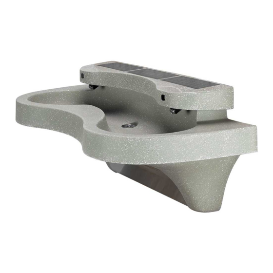
Express® Lavatory System MG-Series
with ndite™ Infrared Control
Express® Lavatory
Systems are ADA and
TAS compliant.
Patents Pending
IMPORTANT!
P.O. Box 309, Menomonee Falls, WI 53052-0309
Phone: 1-800-BRADLEY Fax: (262) 251-5817
http:\\www.bradleycorp.com
TAS
Advertisement
Table of Contents
Troubleshooting

Related Manuals for Bradley Express MG-2/NDT


Summary of Contents for Bradley Express MG-2/NDT
- Page 1 Product warranties may be found under "Product Information" on our web site at www.bradleycorp.com. 215-1587 Rev. C; EN 06-915 P.O. Box 309, Menomonee Falls, WI 53052-0309 Phone: 1-800-BRADLEY Fax: (262) 251-5817 © 2007 Bradley Corporation http:\\www.bradleycorp.com Page 1 of 22...
-
Page 2: Table Of Contents
(8) 3/8" wall anchors, bolts and 1" min. O.D. washers to mount main frame and bowl to wall (minimum pull-out rating of 1,000 lbs.) 1/2" NPT hot and cold supply piping 1-1/2" NPT drain piping 2/12/07 Bradley Corporation • 215-1587 Rev. C; EN 06-915... -
Page 3: Mg-2/Ndt Dimensions - Front, Top And Side Views
27" (686mm) 47" (1194mm) 22" (559mm) 9-1/2" (241mm) 21-1/2" *39" (546mm) (991mm) *33-1/2" (851mm) *29-1/2" *17-1/2" (749mm) (445mm) *Subtract 4" (102mm) from vertical dimensions for compliance with ADA guidelines for children's use. Bradley Corporation • 215-1587 Rev. C; EN 06-915 2/12/07... - Page 4 (762mm) TAS Juvenile Height Grades Pre-K thru 5 or 6 26" (660mm) 14" (356mm) 37-1/2" (952mm) 32" TAS Juvenile Height (813mm) Grades 6 thru 8 or 9 28" (711mm) 16" (406mm) 2/12/07 Bradley Corporation • 215-1587 Rev. C; EN 06-915...
-
Page 5: Installation Instructions
3/8" WALL ANCHORS (8) PLACES MIN. PULL-OUT STRENGTH 1000 LBS. PER ANCHOR *Juvenile Height Mounting: Subtract 4" (102mm) from vertical dimensions for compliance Figure 1 with ADA guidelines for children's use. Bradley Corporation • 215-1587 Rev. C; EN 06-915 2/12/07... - Page 6 (622) 18" (457) FLOOR 1/2" NPT HOT AND COLD SUPPLIES OR TEMPERED SUPPLY – STUB OUT 2" Figure 1b 3/8" WALL ANCHORS (8) PLACES MIN. PULL-OUT STRENGTH 1000 LBS. PER ANCHOR 2/12/07 Bradley Corporation • 215-1587 Rev. C; EN 06-915...
-
Page 7: Step 2 Rough-In Wall Anchors
NOTE: The anchors will be used to mount the Express® bowl and frame to the wall. 1-1/2" NPT DRAIN STUB OUT 2" 1/2" NPT HOT AND COLD SUPPLIES OR TEMPERED SUPPLY. STUB OUT 2" Figure 2 Bradley Corporation • 215-1587 Rev. C; EN 06-915 2/12/07... -
Page 8: Step 3 Mount Frame To Wall
FRAME END CAP LEFT 3/8" BOLTS AND WASHERS (6) PLACES TERREON® END CAP RIGHT 1/4" - 20 SCREWS STAINLESS STEEL AND FINISHING ACCESS PANEL WASHERS (5) PLACES FRONT VIEW Figure 3 2/12/07 Bradley Corporation • 215-1587 Rev. C; EN 06-915... -
Page 9: Step 3 Install Bowl Assembly
FRAME AND WASHER 3/8" BOLT SPRAYHEAD AND WASHER BOWL 1/4"-20 x 1/2" PAN HEAD SCREWS AND TERREON® TERREON® WASHERS END CAP (R) END CAP (L) (2) PLACES BACK VIEW Figure 4 Bradley Corporation • 215-1587 Rev. C; EN 06-915 2/12/07... -
Page 10: Step 5 Connect Electrical And Supply Tubing
1/2" NPT COLD WATER SUPPLY SLOT IN FLEXIBLE SUPPLY FRAME HOSE Figure 5a Figure 5b Single FLEXIBLE SUPPLY HOSE Tempered (TO SOLENOID BRACKET) Supply TEMPERED TO SUPPLY LINE LINE ADAPTER (S39-685) Figure 5c 2/12/07 Bradley Corporation • 215-1587 Rev. C; EN 06-915... -
Page 11: Step 6 Complete Installation
4. Align the valve bracket mounting screws with slots on the frame. Let the valve bracket slide down to lock into place. NOTE: Optional Battery Power Pack (p/n S65-284) for quickstart power-up is available from Bradley. IMPORTANT: The Vernatherm™ valve is NOT factory-preset. Upon installation, the valve temperature must be checked and adjusted to ensure delivery of safe water temperature. - Page 12 SENSOR CABLE (FROM SPRAYHEAD, R/H STATION) POWER-IN CABLE GANG VALVE CIRCUIT BOARD POWER SUPPLY CABLE GANG VALVE ASSEMBLY COMPRESSION NUT (RED SUPPLY, L/H STATION) COMPRESSION NUT (GREEN SUPPLY, R/H STATION) Figure 6b 2/12/07 Bradley Corporation • 215-1587 Rev. C; EN 06-915...
-
Page 13: Cleaning And Maintenance Instructions
• Repair kit: In the unlikely event your Terreon® surface becomes damaged, it can easily be repaired. Contact your Bradley representative to order a repair kit and be sure to specify color when ordering. Stainless Steel Access Panel cleaning Stainless steel is extremely durable, and maintenance is simple and inexpensive. -
Page 14: Assembly Of Components
BOWL MOUNTING (P16-072) HARDWARE 1/8" RUBBER WASHER 1/4"-20 x 1/2" 1/4"-20 (125-001DP) PAN HEAD WASHER SCREW (qty. 2) (qty. 2) (160-389) (142-002DB) P-TRAP (POLYPROPYLENE) TAILPIECE (269-1697) (129-056) OPTIONAL P-TRAP (CHROME-PLATED BRASS) (S29-094) 2/12/07 Bradley Corporation • 215-1587 Rev. C; EN 06-915... - Page 15 FRAME 5/16" I.D. BRAIDED HOSE VERNATHERM™ MIXING VALVE Figure 9 SOLENOIDS SPRAYHEAD AERATOR SPRAYHEAD BODY ASSEMBLY S05-166 MOUNTING LOCATION Figure 10 TO BOWL (3) PLACES Bradley Corporation • 215-1587 Rev. C; EN 06-915 2/12/07...
- Page 16 60" (251-019B) INFRARED WINDOW 269-1241 SPRAYHEAD 110-115 CONNECTOR 1/4" TUBE 145-089 ACCESS PLATE 150-201 SCREW BUTTON HD SOCKET HOUSING, #10-24 160-138 Figure 10a FLOW CONTROL S05-142 WINDOW PURPLE EYE Figure 10b 2/12/07 Bradley Corporation • 215-1587 Rev. C; EN 06-915...
- Page 17 Installation MG-2/NDT Assembly of Components continued . . . POWER-IN CABLE POWER SUPPLY CABLES POWER MANAGEMENT MODULE (S83-182) OPTIONAL BATTERY PHOTOVOLTAIC START-UP PACK CELL PLUG (S65-284) (S83-183) (FROM PHOTOVOLTAIC COVER) Bradley Corporation • 215-1587 Rev. C; EN 06-915 2/12/07...
-
Page 18: Troubleshooting Ndite™ Components
NOTE: If there is inadequate lighting in the location where the unit is installed, add additional lighting or convert the system to battery power. Contact Bradley and order Battery Pack Kit S45-2083 (one per station). - Page 19 Wait for ten seconds. Activate the problem station’s sensor ten times. The station should turn on. If it turns on, and cycles normally, replace the batteries in the problem station. Bradley Corporation • 215-1587 Rev. C; EN 06-915 2/12/07...
-
Page 20: Solenoid Valve Components
O-RING, #2-013 SOLENOID VALVE W/CIRCUIT BOARD CLOSED BODY (S07-088) THRU BODY (S07-088A) CIRCUIT BOARD (S83-184) PAN-HEAD SCREW 6-19 x 3/4" (160-451) VALVE ASSEMBLY CLOSED BODY (S07-072) THRU BODY (S07-072A) Figure 11 2/12/07 Bradley Corporation • 215-1587 Rev. C; EN 06-915... -
Page 21: Thermostatic Mixing Valve Maintenance And Troubleshooting
2. Place thermostat into container with 115° F water. The pushrod should pop out of the thermostat approximately 1/10". 3. If thermostat pushrod does not pop out, the thermostat must be replaced. Contact your Bradley representative and ask for Repair Kit (part number S65-259). -
Page 22: Thermostatic Mixing Valve Parts
Nut 3/8-24 Hex Jam Item Description Thermostat O-Ring O-Ring O-Ring O-Ring Stem Thermostat Piston Spring Seal Cup Valve Body Strainer (173-028) Figure 12 Tempered Line Adapter Assembly (S39-685) Option Figure 13 Strainer 173-028 2/12/07 Bradley Corporation • 215-1587 Rev. C; EN 06-915...
Need help?
Do you have a question about the Express MG-2/NDT and is the answer not in the manual?
Questions and answers