Table of Contents
Advertisement
Advertisement
Table of Contents

Related Manuals for HMS Networks Ewon Flexy 205


Summary of Contents for HMS Networks Ewon Flexy 205
- Page 1 Flexy 205 INSTALLATION GUIDE IG-0028-00 1.3 en-US ENGLISH...
- Page 2 Important User Information Disclaimer The information in this document is for informational purposes only. Please inform HMS Industrial Networks of any inaccuracies or omissions found in this document. HMS Industrial Networks disclaims any responsibility or liability for any errors that may appear in this document. HMS Industrial Networks reserves the right to modify its products in line with its policy of continuous product development.
-
Page 3: Table Of Contents
Table of Contents Page Preface ..........................3 About This Document .......................3 Document history ......................3 Related Documents ......................3 Trademark Information .....................3 Product Summary........................ 4 Introduction ........................4 Modular Concept of the Flexy 205 ..................4 Features of the Flexy 205 ....................5 General Specification of the Hardware Platform ..............5 Typical applications ......................6 Part Numbers ........................6 Safety, Environmental and Regulatory Information............ - Page 4 Resetting the Flexy 205..................... 23 Normal Boot Sequence ....................23 First Level Reset (User Reset) ................... 23 Second Level Reset (Factory Reset) ................... 23 Reset Impact Matrix ....................... 24 Connector Pinout & Related Specifications ..............25 Main Connector......................25 Specification of the External Power Supply ................. 25 Digital Output &...
-
Page 5: Preface
3 (32) Preface About This Document This document describes the hardware of the Ewon Flexy 205 and explains how to get started with the embedded web site. It also describes the basic software tools needed to install the equipment. For additional related documentation and file downloads, please visit www.ewon.biz/support. -
Page 6: Product Summary
Product Summary 4 (32) Product Summary Introduction The Flexy 205 is a modular industrial M2M router. It has been designed to fulfill the following key requirements: • Flexible WAN, allowing within the same product to address different Internet connectivity technologies (Ethernet, Wi-Fi, 4G,…) and securing the investment in case of technology upgrade (eg. -
Page 7: Features Of The Flexy 205
WAN communication interface (Ethernet WAN, wireless modem, ...) • a field communication interface (serial, IO card, …) How the extension cards should be integrated in the Ewon Flexy 205 is explained in Extension Cards, p. Features of the Flexy 205 The following section lists the different main features supported by the Flexy 205. -
Page 8: Typical Applications
Product Summary 6 (32) Typical applications Some of the typical applications for the Flexy 205 are the following ones: • Remote access of Ethernet, serial and MPI devices • Industrial VPN router • Remote monitoring Part Numbers Available Part Numbers Type Part Number Description... -
Page 9: Safety, Environmental And Regulatory Information
(ESD). The printed circuit boards (PCBs) of the Ewon Flexy 205 described in the present document are partially exposed when slot fillers are removed to place extension cards. In order to avoid ESD... -
Page 10: Reference Standards For Type Tests
UL 62368-1 • CAN 62368-1 3.4.3 FCC Compliance The Ewon Flexy 205 and its extension cards comply with Part 15 of the FCC Rules. Operating is subject to the following two conditions: • This device may not cause harmful interference •... -
Page 11: Internal Battery
9 (32) Internal Battery The Ewon Flexy 205 contains a CR2032 battery. This battery is used to maintain the real time clock up-to-date even when the unit is not powered. Here is a list of risks and recommendations regarding the battery: •... - Page 12 Safety, Environmental and Regulatory Information 10 (32) Fig. 3 DIN rail mounting position Description DIN rail mounting bracket Fig. 4 Wall mounting position Description Wall mounting bracket (suggested screw dimensions 4,2 x 32 mm) To ensure a proper ventilation of the equipment, a free gap of at least 2 cm must be respected in front of all upper &...
- Page 13 Safety, Environmental and Regulatory Information 11 (32) Fig. 5 Free gap surrounding the Ewon for heat dissipation. 3.7.3 Earthing Earthing the Ewon is necessary to eliminate unwanted transients and to conform to the EMC requirements. Therefore, a functional earth (FE) terminal is available on the main connector as shown in Specification of the External Power Supply, p.
- Page 14 Safety, Environmental and Regulatory Information 12 (32) The host OEM User Manuel (Ewon's manual) must contain clear instructions on how end users can find and/or access the module and the FCC ID IG-0028-00 1.3 en-US Flexy 205 Installation Guide...
-
Page 15: Hardware Description
Hardware Description 13 (32) Hardware Description Label The identification label of the Ewon Flexy 205 is placed on the right hand side of the housing. The different parts of the label are described below: Label Definition Part Number (see syntax in Syntax of the Part Number, p. -
Page 16: Mechanical Dimensions
Physical Interface This section addresses the interface that represents the Ewon Flexy 205. The items numbered in the image below are explained subsequently in separate paragraphs. IG-0028-00 1.3 en-US... - Page 17 Hardware Description 15 (32) Fig. 8 Base Unit Interface LED panel RESET button - BI1 SD card slot Main connector Used to connect the power supply and the digital I/O 2 slots fillers Can be removed and replaced by extension cards Main board communication interfaces: 4 Ethernet Ports 4.3.1 LED Panel...
- Page 18 Related Documents, p. 4.3.4 Main Connector The Flexy 205 is powered via its main connector using a male connector (a mating female connector with screw terminals is delivered with the Ewon Flexy 205). For details see Main Connector, p. 4.3.5 Two Slots for Extensions The slot fillers can be removed to add extension cards.
- Page 19 Hardware Description 17 (32) LED Interface Label Definition Green = LAN port rectan- Orange = WAN port Small Ethernet activity on port 1 square Green steady = Ethernet link OK Green flashing = Ethernet traffic (Rx and Tx) Ethernet activity on port 2 (same as above) Ethernet activity on port 3 (same as above) Ethernet activity on port 4 (same as above) Fig.
-
Page 20: Extension Cards
Extension Card Insertion Wait 30 seconds after turning off the equipment before inserting (or removing) an extension card in order to avoid possible damage to the Ewon Flexy 205 and the extension cards. Remove the slot filler of the location the new card will be inserted. To do this, press on both ends of the cover, note that the hooks are off-centered. -
Page 21: Powering On The Flexy 205 With Its Extension Cards
5.4.2 Software Compatibility of Multiple Cards Combination The Ewon Flexy 205 allows the insertion of multiple extension cards of the same type. Some configurations including multiple extension cards, even if mechanically acceptable, are not supported by the embedded software. Cards in excess are ignored during the automated detection process which means that the Flexy 205 and its running extension cards will operate normally. -
Page 22: Ethernet Extension Card - Flx 3101
Extension Cards 20 (32) Fig. 14 Order of the Extension Cards The picture above shows an example of a configuration that would be OK mechanically and power wise but would not be supported by the firmware. During the boot process, the first 2 serial port extension cards are detected and both can be used. In case of 2 single Ethernet cards, these 2 cards are also detected but the second single Ethernet card is not supported by the firmware and so it cannot be used. -
Page 23: Ip Address & Access To The Web Configuration
IP Address & Access to the Web Configuration 21 (32) IP Address & Access to the Web Configuration Factory Default IP Settings Characteristics Values LAN IP address 10.0.0.53 LAN subnet mask 255.255.255.0 Gateway 0.0.0.0 The WAN IP address is set by default in DHCP mode. Powering On Power the unit on and wait approximately 25 seconds until the boot process is completed. - Page 24 IP Address & Access to the Web Configuration 22 (32) Another way to access the web panel of the Flexy 205 is by using eBuddy with its EZ DHCP feature. For more info, refer to eBuddy from the Related Documents, p. Before beginning the configuration of the Flexy 205, an authentication is required.
-
Page 25: Resetting The Flexy 205
23 (32) Resetting the Flexy 205 The reset button BI1 is located at the bottom right of the Ewon Flexy 205 (see Reset Button, p. 15). The reset function of this button is active only if pressed while powering on. The Flexy 205 features two type of reset levels. -
Page 26: Reset Impact Matrix
Resetting the Flexy 205 24 (32) Check if the auto test is successful, the USR LED blinks red following a pattern of 200ms ON and 1,5 sec OFF. The Flexy 205 does not restart in normal mode by itself and remains in this diagnose mode. -
Page 27: Connector Pinout & Related Specifications
Specification of the External Power Supply The Ewon Flexy 205 must be powered by a 12-24Vdc 100w max. certified for 60°C and for altitudes up to 2000m for conformity to the UL/IEC 62368-1 or by a safety Low Power Supply (LPS) in accordance with clause 2.5 of UL/IEC 60950-1 Ed2. -
Page 28: Digital Output & Digital Inputs
Appendix A: Connector Pinout & Related Specifications 26 (32) Digital Output & Digital Inputs Fig. 16 Current scheme of the main connector Characteristic Value Type of digital output Open drain MOSFET 200 mA Maximum current (ext,source) Isolation (both DI & DO) 1.5 kV DI voltage range 0 to 30 VDC... - Page 29 Appendix A: Connector Pinout & Related Specifications 27 (32) Fig. 17 External wiring for the Digital Output A.3.1 Possible Features Wiring the Digital Output & Inputs can be used to externalize some features (as connectivity condition) as described below: Connector Description Authorize or prevent the Internet connection.
-
Page 30: B Flexy 205 Products Overview
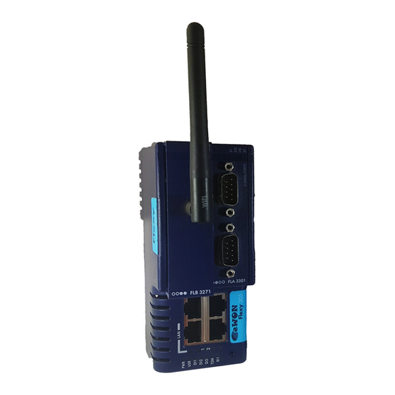
Appendix B: Flexy 205 Products Overview 28 (32) Flexy 205 Products Overview Extension Cards Picture Reference & name Slot compatibility Maximum supported Installation Guide FLA 3301 ●●○○ IG-0016-00 2 Serial-Ports FLX 3101 ●●●● IG-0017-00 Ethernet 10/100 FLX 3401 ●●●● IG-0018-00 8DI-4AI-2DO FLX 3402 ●●●●... - Page 31 Appendix B: Flexy 205 Products Overview 29 (32) Picture Reference & name Slot compatibility Maximum supported Installation Guide FLB 3204 ○○●● IG-0026-00 4G EU FLB 3271 ○○●● IG-0020-00 Wi-Fi FLA 3501 ●●○○ IG-0021-00 PSTN FLB 3601 ○○●● IG-0024-00 FLC 3701 ○○○○...
-
Page 32: C Flexy 205 Isolation Scheme
Appendix C: Flexy 205 Isolation Scheme 30 (32) Flexy 205 Isolation Scheme Base Unit Flexy 205 Connector shielding Earth connected Ethernet signals Isolated from DGNG with a transformer Serial ports GND = DGND Fig. 18 Isolation Scheme for the Base Unit Based on the above picture: •... - Page 33 Appendix C: Flexy 205 Isolation Scheme 31 (32) C.2.3 FLX 3271 – Wi-Fi DGND = GND RF from SMA connector Avoid external connections between GND RF and Earth. C.2.4 FLX 340x – I/O DO signals: isolated relays outputs DI signals: isolated from DGND (optocoupler) AI signals: isolated from PGND only AI-GND = DGND C.2.5...
- Page 34 last page © 2019 HMS Industrial Networks Box 4126 300 04 Halmstad, Sweden info@hms.se IG-0028-00 1.3 en-US / 2019-11-22 / 16225...
Need help?
Do you have a question about the Ewon Flexy 205 and is the answer not in the manual?
Questions and answers