HMS Networks Intesis INBACRTR0320000 Installation Sheet
Bacnet ms/tp to bacnet ip router
Hide thumbs
Also See for Intesis INBACRTR0320000:
- Installation manual (2 pages) ,
- User manual (37 pages)
Advertisement
Quick Links
INBACRTR0320000
Intesis BACnet MS/TP to BACnet IP router
Order Code: INBACRTR0320000
** stands for the Intesis gateway capacity and varies depending on the specific gateway acquired
Installation Sheet rev.1.5
HMS Industrial Networks S.L.U ©
SAFETY INSTRUCTIONS
WARNING
!
Follow carefully this safety and installation instructions.
Improper work may lead to serious harmful for your health
and may also damage seriously the gateway and/or any
other equipment connected to it.
The gateway must be installed by accredited electrician or similar
technical personnel, following all the safety instructions given here and
in accordance always with the country legislation for installation of
electric equipment.
The gateway cannot be installed outdoors or exposed to direct solar
radiation, water, high relative humidity or dust.
The gateway must only be installed in a restricted access location.
In case of wall mount, fix firmly the gateway on a not vibrating surface
following the instructions next.
In case of DIN rail mount fix the gateway properly to the DIN rail
following the instructions below.
Mounting on DIN rail inside a metallic cabinet properly connected to
earth is recommended.
Disconnect always power of any wires before manipulating and
connecting them to the gateway.
A power supply with an NEC Class 2 or Limited Power Source (LPS)
and SELV rated is to be used.
Respect always the expected polarity of power and communication
cables when connecting them to the gateway.
Supply always a correct voltage to power gateway, see details of
voltage range admitted by the device in the technical characteristics
below.
CAUTION: The device is to be connected only to networks without
routing to the outside plant, all communication ports are considered for
indoor only.
This device was designed for installation in an enclosure. To avoid
electrostatic discharge to the unit in environments with static levels
above 4 kV, precautions should be taken when the device is mounted
outside an enclosure. When working in an enclosure (ex. making
adjustments, setting switches etc.) typical anti-static precautions
should be observed before touching the unit.
Safety instructions in other languages can be found at:
https://intesis.com/docs/manuals/v6-safety
CONFIGURATION
Use the Configuration Tool to configure the gateway.
See instructions to download and install the latest version at:
https://intesis.com/docs/software/intesis-maps-installer
Use the Ethernet connection for communication between the gateway
and the configuration tool. See CONNECTIONS below and follow
instructions of user's manual for more details.
Rev.1.5
© HMS Industrial Networks S.L.U - All rights reserved
This information is subject to change without notice
Owner's Record
The serial number is located at the rear of the gateway.
Record this information in the space provided below.
Refer to it whenever you contact upon your gateway
dealer or support team regarding this product.
Serial No.
INSTALLATION
Follow instructions next to properly install the gateway.
Disconnect from mains the power supply before connecting it to the
gateway.
Disconnect power of any bus or communication cable before
connecting it to the gateway.
Mount the gateway in a vertical position on the wall or DIN rail following
the instruction given below, respecting the safety instructions given
above.
IMPORTANT: Connect a NEC Class 2 or Limited Power Source (LPS)
and SELV rated power supply to the gateway, respect the polarity if DC
power or Line and Neutral if AC power. This power supply must not
be shared with other devices. Apply always a voltage within the
range admitted by the gateway and of enough power (see technical
characteristics).
Circuit-breaker must be used before the power supply. Rating 250V-
6A.
Connect the communication cables to the gateway, see details on the
user's manual.
Power the gateway and the rest of devices connected to it.
Wall Mount
1. Separate the fixing clips in the bottom of the box, pushing
them to the outside until hear the "click" which indicates that
now the clips are in position for wall mount, see in the figure
below.
2. Use the holes of the clips to fix the box in the wall using
screws. Use the template below for the wall wholes.
Press
Clips in their original position
(for DIN rail mount)
DIN Rail Mount
With the clips of the box in their original position, insert first the box
in the upper edge of the DIN rail and later insert the box in the down
part of the rail, using a small screwdriver and following the steps in
the figure below.
1
3
Clips in position for wall mount
DIN Rail
2
URL
https://www.intesis.com
1 / 2
Advertisement

Related Manuals for HMS Networks Intesis INBACRTR0320000


Summary of Contents for HMS Networks Intesis INBACRTR0320000
- Page 1 Owner’s Record The serial number is located at the rear of the gateway. INBACRTR0320000 Record this information in the space provided below. Intesis BACnet MS/TP to BACnet IP router Refer to it whenever you contact upon your gateway dealer or support team regarding this product. Order Code: INBACRTR0320000 ** stands for the Intesis gateway capacity and varies depending on the specific gateway acquired Serial No.
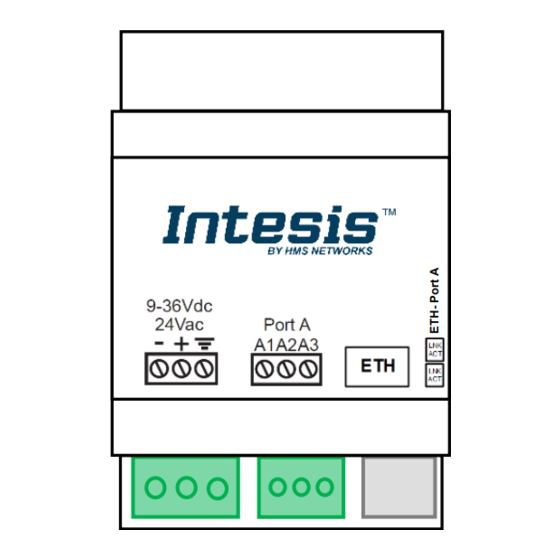
- Page 2 CONNECTIONS Power Supply Must use NEC Class 2 or Limited Power Source (LPS) and SELV rated power supply. Respect polarity applied of terminals (+) and (-). Be sure the voltage applied is within the range admitted (check table below). The power supply can be connected to earth but only through the negative terminal, never through the positive terminal.
Need help?
Do you have a question about the Intesis INBACRTR0320000 and is the answer not in the manual?
Questions and answers