Advertisement
Quick Links
Installation Instructions
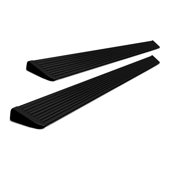
PowerBoard
Automatic Retracting Running Board
www.Bestop.com
- We're here to help! Visit our web site and click on
INSTALLATION TIME
3 Hours
TOOLS
10mm, 13mm
10mm and
and 19mm
13mm
5mm
®
NX
SKILL LEVEL
3 - Moderately Diffi cult
Vehicle Application
• Dodge Ram 1500 Crew Cab
2009 - Current
Part Number: 75638-15
• Dodge Ram 2500/3500 Mega Cab
2010 - Current
Part Number: 75638-15
Patent Pending
"Ask a
Question". Click here for more
• Dodge Ram 1500 Quad Cab
2009 - Current
Part Number: 75643-15
Truck Accessories by Bestop.
Advertisement

Subscribe to Our Youtube Channel
Related Manuals for Bestop PowerBoard NX


Summary of Contents for Bestop PowerBoard NX
-
Page 1: Installation Instructions
Part Number: 75638-15 Patent Pending www.Bestop.com - We’re here to help! Visit our web site and click on “Ask a Question”. Click here for more Truck Accessories by Bestop. INSTALLATION TIME SKILL LEVEL 3 Hours 3 - Moderately Diffi cult TOOLS... - Page 2 PowerBoard ® NX – Installation Instructions Parts List and Hardware Identifi cation Left End Cap, M6-1.0 x 15 Socket Cap Screw, Running Board Assembly, Qty - 2 Part Number Part Number 481.93, Qty - 2 72" - Part Number 473.14 460.83, Qty - 1 T-Nut Insert, Part 79"...
- Page 3 If the system does not operate as stated above see the Troubleshooting and Battery Replacement sections at the end of the instructions or go to our web site at http://www.bestop.com/support. Receiver Rev. G 0713 75638 / 75643 pg. 3...
- Page 4 ® PowerBoard NX – Installation Instructions Steps 2 through 5 are for Quad Cab Install Brake Cable Bracket - Install Brake Cable Bracket - Vehicles only. If you have Crew Cab, Quad Cab Only Quad Cab Only skip to Step 6. Once you have enough slack, detach the brake Depress the locking tabs on the brake cable guide cable just behind the brake cable adjustment nut.
- Page 5 ® PowerBoard NX – Installation Instructions Install Reinforcement Bracket Install Blind Rivet Install Rivet Nuts Assemble a Hex Bolt, Rivet Nut Tool and Rivet Nut. Once the hole is drilled, insert a piece of string or Set the Rivet Nuts into place for alignment. Make Place the assembly into the cutout in the sill.
- Page 6 ® PowerBoard NX – Installation Instructions Install Linkages Orient Linkages Retract the Linkage part way and make sure the Mounting Insert is in the Orient the Linkages on the vehicle with the Idler Linkages to the rear and the proper position. Tilt the Linkage and slide the mounting slots over the bolts Motor Linkages to the front.
- Page 7 ® PowerBoard NX – Installation Instructions Install Support Bracket Secure Support Bracket Install Bracket Insert Slide the slotted end Thread an M8-1.25 x 30 Hex Bolt and Large Washer Align the lower hole in the M8-1.25 x 30 Hex Bolt into a Bracket Insert.
- Page 8 ® PowerBoard NX – Installation Instructions Route Wiring Harness – Do Not install on or near Route Wiring Harness – hot surfaces. Driver’s Side Driver’s Side On the driver’s side route the Wire Harness down Continue to route the Wire Harness along the inside Route Wiring Harness along the underside of the fl...
- Page 9 PowerBoard ® NX – Installation Instructions Install Running Boards Install Motor Mount the Steps to the linkages. Slide the mounting T-Nut Slide Motor assembly onto drive shaft and mounting into position. Install M6-1.0 x Socket Head Bolts to secure bosses of Motor Linkage assembly. Use three (3) the boards.
- Page 10 ® PowerBoard NX – Installation Instructions Install Driver’s Side Install Magnet Driver’s Side Rear Sensor Rear Door Driver’s Side Peel the liner off of the Drivers Side Rear Rear Door Open the front driver’s side door and Sensor. Position it on the door pillar so clean the area where the magnet and Magnet Magnet...
- Page 11 ® PowerBoard NX – Installation Instructions Install Lights Test Doors and PowerBoards ® Clean the outboard surface Open and shut each door to make sure the Power- ® of the of the Linkage below Boards deploy and retract. There is a slight delay the bottom mounting bolt.
- Page 12 ® PowerBoard NX – Installation Instructions PowerBoard ® NX Troubleshooting Linkage Component Identifi cation Delay in board operation or boards operate Issue: after doors are shut: • Possible cause • Magnet is too far away from Sensor Motor Gear Mounting Boards do not operate: Shaft •...
- Page 13 ® PowerBoard NX – Installation Instructions Battery Replacement This device complies with Industry Canada licence- exempt RSS standard(s). Operation is subject to Each sensor is powered by a CR2450 3 volt bat- the following two conditions: (1) this device may not tery that may periodically need to be replaced.
-
Page 14: Limited Warranty
This warranty gives you specifi c legal rights, and you may also have other rights which vary from state to state. For further information or request for warranty work, please contact: Bestop Inc. Customer Service Toll-Free: (800)845-3567 Main: (303)465-1755 E-mail: csbestop@Bestop.com...
Need help?
Do you have a question about the PowerBoard NX and is the answer not in the manual?
Questions and answers