Table of Contents
Advertisement
Quick Links
Short guide
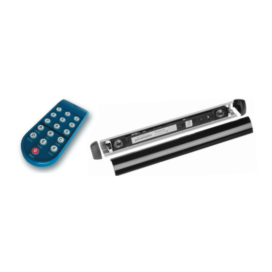
Uniscan / US beam
Installation and adjustment
1. Fit housing (see operating instructions, chapter 2).
2. Click US beams into aluminium profiles.
3. Check whether the US beams are clicked in correctly and therefore secured
well in the profile!
3. . Position US beams and set inclination angle
The left and right bearing clamps must be at the same angle
(see operating instructions, chapter 4.3).
4. If several sensors are used, connect these with the ribbon cable
(see operating instructions, chapter 4.1).
5. Click cover onto profile (working from front to back) and ensure that the
US beam's inclination angle doesn't change!
Electrical connections
Diagram for door side A or B:
1
2
common
3
nc*
4
no*
5
Test input
6
Initialisation (see operating instructions, chapter 4)
a) Initialisation is undertaken by pressing the keys F + 3 + 6 on the Reglobeam remote control or by pressing the green key for 5 seconds!
b) If both LEDs (red/green) flash, this indicates that the function has been triggered. The detection area must be exited within 6 seconds.
c) If the red LED then flashes, this indicates that initialisation is under way. The detection area must not be entered during this time!
d) Initialisation is complete when both LEDs go out.
Reglobeam remote control
General:
If G flashes, a connection to the sensor could not be established.
Disconnect the power supply of the UniScan briefly or press the two
buttons on the sensor for 1 second.
Direct the Reglobeam remote control more exactly and directly at the
sensor.
30 minutes after the last setting was undertaken on the sensor,
configuration mode is automatically exited.
Settings with Reglobeam
Key
Function
A
Test input
Switch light points on and off
B
Note: Once one or more beams have been
switched on and off, re-initialise using F+3+6
C
Output signal
D
Sensitivity
Factory setting, *Setting not TÜV-compliant regarding type approval, **above a mounting height of 2.7 m, setting not TÜV-compliant regarding type approval
Bircher Reglomat AG, headquarters Switzerland Tel. +41 (0)52 687 11 11, Germany Tel. +49 (0)7031 70 60 0
Diagram for door controller with Y adapter:
test input
To sensor master
no
on the front of the
nc
door (hinge side of
common
the door)
To sensor master
on the back of the
common
nc
door(non-hinge side
no
of the door)
test input
Key
Brief description of function
1
«High» active, pull up
2
«High» active, pull down
3
«Low» active, pull up
4
«Low» active, pull down
5
Test input deactivated*
1+ 1 oder 2
Beam 1 selected, activate with key 1, deactivate with key 2
2+ 1 oder 2
Beam 1 selected, activate with key 1, deactivate with key 2
3+ 1 oder 2
Beam 1 selected, activate with key 1, deactivate with key 2
4+ 1 oder 2
Beam 1 selected, activate with key 1, deactivate with key 2
5+ 1 oder 2
Beam 1 selected, activate with key 1, deactivate with key 2
6+ 1 oder 2
Beam 1 selected, activate with key 1, deactivate with key 2
7+ 1 oder 2
Beam 1 selected, activate with key 1, deactivate with key 2
8+ 1 oder 2
Beam 1 selected, activate with key 1, deactivate with key 2
9
All beams on
1
The relay picks up when a detection takes place (active)
2
The relay drops out when a detection takes place (passive)
6
Restart
1
Object height > 10 cm
2
Object height > 20 cm if sensor mounting height is up to 3 m
3
Object height > 20 cm if sensor mounting height is up to 2.7 m
4
Object height > 30 cm**
5
Object height > 50 cm**
6
Object height > 70 cm**
7
Object height > 100 cm*
This information sheet does not replace the
original operating instructions!
Read the operating instructions before
commissioning the device!
6
5
1 test input
4
2 no
3
3 nc
2
4 common
1
–
5
⁄~
To door controller
1
6 +/ ~
2
7 common
3
8 nc
4
9 no
5
10 test input
6
Factory setting: Energy-saving beam pattern 1-3-5-7-8 on
Note:
Single operation is only possible
with an alternating current supply!
Page 1 of 2
Advertisement
Table of Contents

Related Manuals for Bircher Reglomat US beam


Summary of Contents for Bircher Reglomat US beam
- Page 1 Factory setting, *Setting not TÜV-compliant regarding type approval, **above a mounting height of 2.7 m, setting not TÜV-compliant regarding type approval Page 1 of 2 Bircher Reglomat AG, headquarters Switzerland Tel. +41 (0)52 687 11 11, Germany Tel. +49 (0)7031 70 60 0...
- Page 2 Function Brief description of function 0 ms 50 ms (ms=milliseconds, s=seconds) 200 ms Relay hold interval 10 s F + 1 Device address 1– 7 Address of between 1 and 7 can be selected, factory setting is 3 Standard floor F + 2 Composition of the floor Dark or reflective floor...
Need help?
Do you have a question about the US beam and is the answer not in the manual?
Questions and answers