
Related Manuals for Ghibli & Wirbel RUNNER R 150 FD 85


Summary of Contents for Ghibli & Wirbel RUNNER R 150 FD 85
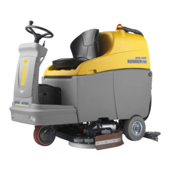
- Page 1 www.ghibliwirbel.com Professional Cleaning Machines Since 1968 49.0250.00_EN ed. 07-2019 Technician’s Manual...
- Page 3 Index RUNNER English ..................07-2019...
-
Page 5: Table Of Contents
Technician’s Manual RUNNER INDEX ................Introduction 1.1 General safety warnings ................3 Removals / replacements ................... 4 2.1 Flashing light bulb replacement ..............4 2.2 Flashing light removal................. 4 2.3 Seat removal ....................5 2.4 Seat plate removal ..................6 2.5 Sensor level replacement ................ - Page 6 Technician’s Manual RUNNER 2 / 50-ENGLISH 07-2019...
-
Page 7: Introduction
Technician’s Manual RUNNER 1. INTRODUCTION - This manual has been written by for exclusive use by the authorized technicians of the manufacturer. 1.1 General safety warnings - To make sure when working on the machine, it is necessary that the batteries are di- sconnected and that the tanks are empty. -
Page 8: Removals / Replacements
Technician’s Manual RUNNER 2. REMOVALS / REPLACEMENTS 2.1 Flashing light bulb replacement - Unscrew the reflector (1) by hand and remove it. - Remove the bulb (2) and turn it 1/2 of a turn. - Replace the bulb and reassemble the reflector. 2.2 Flashing light removal - Unscrew the reflector as indicated in the previous paragraph “Flashing light bulb replacement”. -
Page 9: Seat Removal
Technician’s Manual RUNNER - Unscrew the two screws (4) of the power supply wires (5). - Remove the flashing light (6) by unthreaded the wi- res (5). 2.3 Seat removal - Make sure that the recovery tank (1) is empty, if so empty it as indicated in the user manual. -
Page 10: Seat Plate Removal
Technician’s Manual RUNNER - Lower the tank (1) and remove the seat (2). 2.4 Seat plate removal - Remove the seat as indicated in the previous para- graph. - Unscrew the hexagonal screws (1) and the allen screw (2). - Remove the plate (3). 2.5 Sensor level replacement - Remove the seat as indicated in the relevant para- graph. -
Page 11: Gas Spring Replacement
Technician’s Manual RUNNER - Clean the residue of glue remaining on the tank with a suitable product, then remove the film (5) and mount a new sensor (3) by using the dou- ble-sided adhesive present. - Connect the connector (4). 2.6 Gas spring replacement - Lift the recovery tank in two operators making sure it is empty. -
Page 12: Vacuum Motor Removal
Technician’s Manual RUNNER 2.7 Vacuum motor removal - Lift the recovery tank in two operators making sure it is empty. - Unscrew the four screws (1) and remove the cover (2). - Cut the safety cable tie (3) of the connector (4). - Disconnect the connector (4). - Page 13 Technician’s Manual RUNNER - Remove the soundproofing (6). - Unscrew the four screws (7) that block the vacuum motor (8) to the tank.. - Remove the vacuum motor (8). - Recover the flange (9) and the gasket (10). 9 / 50-ENGLISH 07-2019...
-
Page 14: Recovery Tank Removal
Technician’s Manual RUNNER - Replace the vacuum motor and reassemble by proceeding in the reverse order to disassembly, making sure to position the gasket (11) as shown in the figure. When reassembling the soundproofing (6) make sure it is positioned in the origi- nal position. - Page 15 Technician’s Manual RUNNER - Remove the R-clip (5) of the tank rotation pins. - Remove the washer (6). - Place a cardboard (7) and with a screwdriver (8) pry off to extract the pin. (9). - Lift the tank in two operators (10). - Reassemble the tank by proceeding in reverse or- der.
-
Page 16: Rear Wheels Removal
Technician’s Manual RUNNER 2.9 Rear wheels removal - Lock the machine in place so that it does not move. - Insert a jack (1) under the chassis in the position shown in the figure. - Lift the machine so that the wheel (2) is raised off the floor. - Page 17 Technician’s Manual RUNNER - Release the clamp (2) of the drain hose (3). - Remove the cable clamp plates (4) by unscrewing the relevant screws. - Disconnect the electrical wiring (5) from the clean water tank. - Unscrew the ring nut (6) and remove the filter. - Unscrew the four nuts (7) positioned on the rear of the machine.
-
Page 18: Flowmeter Replacement
Technician’s Manual RUNNER 2.11 Flowmeter replacement Make sure the clean water tank is empty. - Unscrew the two allen screws (1) that fix the flow- meter (2) to the support. - Disconnect the wiring (3) by releasing the relevant connector. - Release the cable ties (4) and remove the flowme- ter (2). -
Page 19: Squeegee Arms Replacement
Technician’s Manual RUNNER - Remove the complete support (4). 2.13 Squeegee arms replacement - Release the chain link (1) and remove the chains (2). - Unscrew the joint (3) from the machine plate (4). Unscrew the joint (4) from the squeegee support plate (5) and remove the arm (6). -
Page 20: Solenoid Valve Replacement
Technician’s Manual RUNNER - Before reassembling the arm (6) check that the di- stance between the two joints (3) and (4) is 120 mm, if it is not correct, adjust it by loosening the lock nut (5) and turning the joint (4). 120 mm 2.14 Solenoid valve replacement Make sure the clean water tank is empty. -
Page 21: Underbody Gas Spring Removal
Technician’s Manual RUNNER - Unscrew the two screws (5) and remove the water pump (6). When replacement the water pump, ti- ghten the two fittings (3) and (4) manually without exaggerating. 2.16 Underbody gas spring removal - The underbody gas spring are two, one on the ri- ght and one on the left of the body and they are used to adjust the pressure on the ground of the brushes. -
Page 22: Brushes Deck Actuator Removal
Technician’s Manual RUNNER 2.17 Brushes deck actuator removal - Lower the brushes deck and the squeegee. - Remove the left wheel as indicated in the relevant paragraph. - Remove the underbody gas spring from the left side of the body as indicated in the relevant para- graph. -
Page 23: Squeegee Actuator Removal
Technician’s Manual RUNNER - Remove the R-clip (6) of the pin (7). - While supporting the brushes deck actuator (8) with one hand, remove the pin (7). - Remove the brushes deck actuator (8) from the front left side of the machine. 2.18 Squeegee actuator removal - Open the detergent compartment (1) by release... - Page 24 Technician’s Manual RUNNER Remove the detergent tank (3). - remove the tray (4). Loosen the clamp (5) and disconnect the connec- tor (6). - From the left rear part of the machine, remove the R-clip (7) and its washer. 20 / 50-ENGLISH 07-2019...
-
Page 25: Squeegee Lifting Cable Replacement
Technician’s Manual RUNNER - Remove the pin (8) from the right rear side. - Remove the R-clip (9) from the front of the machi- - Remove the squeegee actuator (10) from the front left side of the machine. 2.19 Squeegee lifting cable replacement - Remove the squeegee. - Page 26 Technician’s Manual RUNNER - Remove the R-clip (2), remove the pin (3) of the transmission. - Remove the two bearings (4) and the washer (5). - Unscrew the cables (6) from the chain (7). - Unthread the cable (6) completely from the front of the machine.
-
Page 27: Brushes Deck Removal
Technician’s Manual RUNNER - Insert the new cable into the sheath (8) from the front of the machine towards the rear and reas- semble everything proceeding in reverse. When reassembling, make sure that the transmission is correctly fitted by posi- tioning the washer (5) between the two bearings (4) 2.20 Brushes deck removal... - Page 28 Technician’s Manual RUNNER - Disconnect the red connectors (5) for both electri- cal motors. - Sganciare il tubo (6) di alimentazione acqua dal raccordo rapido (7). - From the right side, unhook the chain (8) by remo- ving the chain link (9). - From the right side, with a key, block the rotation of the fitting and with another key unscrew the nut (10) of the articulated head (11) then remove the...
- Page 29 Technician’s Manual RUNNER - On both sides, remove the R-clip (12) and the pin (13) of the limit stop levers (14). - On both sides, unscrew the screw (15) of the lifting brushes deck arms (16), then recover the spacer bushing.
-
Page 30: Electric Gearmotors Removal
Technician’s Manual RUNNER - Remove the complete brushes deck (18). When reassembling, connect the con- nector with the white heat-shrink sheath to the left electric gearmotor. 2.21 Electric gearmotors removal 26 / 50-ENGLISH 07-2019... - Page 31 Technician’s Manual RUNNER - Rotate 180 ° the brushes deck - Remove the brush (1) - Remove the seeger (2). - Remove the brush hub (3). - Remove the key (4) from the shaft motor (5). 27 / 50-ENGLISH 07-2019...
- Page 32 Technician’s Manual RUNNER - Unscrew the four screws (6) and recover their wa- shers, then remove the flange (8). - Unscrew the seven screws (9) and recover their washers, then remove the electric gearmotor (11). When reassembling, make sure that the key (9) is correctly assembled and that the electric gearmotors (11) are installed correctly as they must not be inverted.
-
Page 33: Front Bulb Replacement
Technician’s Manual RUNNER 2.22 Front bulb replacement - Unscrew the two screws (1). - Remove the headlight assembly (2). - Lift the rubber cap (3). - Loosen the screw (4) and move the copper tongue 29 / 50-ENGLISH 07-2019... -
Page 34: Accelerator Removal
Technician’s Manual RUNNER - Remove the bulb (6). 2.23 Accelerator removal - Unscrew the screw (1) and remove the pedal (2) of the accelerator. - Open the clamp (3), disconnect the connector (4) and release the wire. - Unscrew the four screws (5) and remove the acce- lerator box (6). -
Page 35: Steering Angle Microswitch Removal
Technician’s Manual RUNNER 2.24 Steering angle microswitch removal - Unscrew the two screws (1) and remove the bracket (2). - Unscrew the two screws (3) and lower the cover (4). - Unscrew the two screws (5) of the electrical con- nection cables and remove the two cables from the fairlead. -
Page 36: Wheel Motor Removal
Technician’s Manual RUNNER When reassembling a new microswitch do not change the setting of the feeler pin with roller (8), leave the one supplied by the manufacturer. 2.25 Wheel motor removal - Remove the steering angle microswitch bracket as indicated in the previus paragraph. - Place two wedges on the rear wheels so that the machine does not move accidentally. - Page 37 Technician’s Manual RUNNER - Disconnect the motor wheel power supply connec- tor (5) from the control unit (6). - Unthread the connector (5) and place it in the che- mical compartment, then disconnect the electric brake connector (7). - Unscrew and remove the lower screw (8) of the steering column (9).
-
Page 38: Electric Brake Removal
Technician’s Manual RUNNER - Unscrew the four screws (10) fixing the wheel motor. - Lift the front machine with the jacks and remove the wheel motor (11) from the right side. 2.26 Electric brake removal - Remove the wheel motor as indicated in the pre- vius paragraph. -
Page 39: Steering Assembly Removal
Technician’s Manual RUNNER - Disconnect the wires (3) from the connector (4). When reassembling, reconnect the wires to the original position as shown on the figure. - Unscrew the three screws (5) and remove the electric brake (6). 2.27 Steering assembly removal - Remove the wheel motor as indicated in the rele- vant paragraph. - Page 40 Technician’s Manual RUNNER - Unscrew the central screw (3). - By using an aluminum punch (4), hammer the cen- tral part of the steering column and at the same time lift the steering wheel (2) until it is pulled out. - Remove the bellows (5).
-
Page 41: Steering Column Removal
Technician’s Manual RUNNER 2.29 Steering column removal - Remove the control panel and the front panel to access the main electronic board as indicated in the relevant paragraphs. - Loosen the screw (1) of the joint (2). - Unscrew the four screws (3) and remove the stee- ring column (4). -
Page 42: Topography Of Electrical / Electronic Components
Technician’s Manual RUNNER 2.32 Topography of electrical / electronic components 1) General contactor 2) Fuse 10A 3) Horn 4) Main electronic board 5) Brushes deck actuator card 6) Sqeegee actuator card 7) Peristaltic pump 8) Safety by-pass connector 9) Transformer 36/12 V (lights) 9592 38 / 50-ENGLISH 07-2019... -
Page 43: Contactor Replacement
Technician’s Manual RUNNER 2.33 Contactor replacement. Make sure the batteries are disconnected. - Unscrew the two screws (1) and remove the con- tactor (2). - Disconnect the two fastons (3) (4) and unscrew the two nuts by disconnecting the cables (5), (6) and (7). -
Page 44: Resettable Fuse Replacement
Technician’s Manual RUNNER - Disconnect the connector (3) and remove the light transformer (1). 2.36 Resettable fuse replacement - Remove the fuse (1) and replace it with a 10 A re- settable fuse. 2.37 Peristaltic pump replacement Peristaltic head replacement Press the two tabs (1) and remove the peristaltic head (2). -
Page 45: Main Electronic Board Removal
Technician’s Manual RUNNER - Disconnect the connector (8) and remove the peri- staltic motor (9). 2.38 Main electronic board removal - Disconnect all the connectors from the Main electronic board (1). - Unscrew the two nuts (2) and (3) and disconnect the cables (4) and (5). -
Page 46: Dashboard Removal
Technician’s Manual RUNNER When reassembly the Main electronic bo- ard: - Connect the connectors (7) following the numbe- ring shown on the connectors and on the Main electronic board (number by number); - Connect the connector with several wires (8) to the brushes deck actuator board (9) and the connector with two wires (10) to the squegee actuator board (11):... -
Page 47: Switches Removal
Technician’s Manual RUNNER - Disconnect all connectors and remove the dashbo- ard (2). 2.40 Push-buttons removal To remove the push-buttons (1, Flashing light), (2, Lights), (3, Horn) it is necessary to release the rela- tive contact, press the locking tabs and remove the push-button from the front of the dashboard. -
Page 48: Key Block Replacement
Technician’s Manual RUNNER 2.42 Key block replacement - Disconnect the two fastons (1). - Unscrew the nut (2) with its serrated washer. - Remove the key block (3) from the front of dashbo- ard. 2.43 Potentiometer replacement - Loosen the screw (1) and remove the knob (2). - Unscrew the nut (3) with its serrated washer. -
Page 49: Joystick Replacement
Technician’s Manual RUNNER 2.44 Joystick replacement - Disconnect the electrical connections. - Loosen the two screws (1) to lock the electric block (2). - Turn the joystick (3) 1/4 turn and release it from the electric block (2). When reassembly, connect the “Red” wire (R) to the terminals marked “3”, the “Pink”... -
Page 50: Regulations / Controls
Technician’s Manual RUNNER 3. REGULATIONS / CONTROLS 3.1 Peristaltic pump operation check To avoid unnecessary waste of this check, it is advisable to replace the detergent tank with a tank containing water only. For all generic operations concerning the machine operation, refer its use and maintenance manual. -
Page 51: Water Flow Control
Technician’s Manual RUNNER - If the previus adjustment is not sufficient, loosen the screws (3) and lower the skirt rubber (4) by using the slots then tighten the screws (3). 3.3 Water flow control - Start the machine. - Lower the brushes deck. - Switch off the control panel using the key. -
Page 52: Technician Password
Technician’s Manual RUNNER 3.4 Technician password 1) Press and hold the push-buttons 1 and 6 simultaneously, turn the key to ON position and wait for the mes- sage: ID CHEK INSERT PASSWORD: 0. Release the two push-buttons. 2) Use the push-buttons 4 and 5 to change the password value to 70. 3) Confirm with the enter push-button 2. - Page 53 Technician’s Manual RUNNER FLASHING LIGHTS POTENTIOMETER 47K Display ACCELERATOR PEDAL LIGHTS HORN TRANSFORMER 36/12 POWER ON DRIVE FORWARD-BACKWARDS 1 BACKWARDS 2 FORWARD BR 2 - BR 1 - OUT +V OUT +V SEAT MICROSWITCH MICROSWITCH BATTERY STEERING ANGLE - BATT TouchCell +BATT LEVEL...
- Page 54 Technician’s Manual RUNNER 50 / 50-ENGLISH 07-2019...
- Page 56 Professional Cleaning Machines Since 1968 DEALER Ghibli & Wirbel S.p.A. Via Circonvallazione, 5 - 27028 Dorno PV - Italia P. +39 0382 848811 - F. +39 0382 84668 - M. info@ghibliwirbel.com www.ghibliwirbel.com 100% MADE IN ITALY MEMBER OF RIELLO INDUSTRIES...
Need help?
Do you have a question about the RUNNER R 150 FD 85 and is the answer not in the manual?
Questions and answers