
Related Manuals for CHIEF FSB1U


Summary of Contents for CHIEF FSB1U
- Page 1 I N S T A L L A T I O N I N S T R U C T I O N S Universal VESA Interface Spanish Product Description German Product Description Portuguese Product Description Italian Product Description Dutch Product Description French Product Description FSB1U...
-
Page 2: Important Safety Instructions
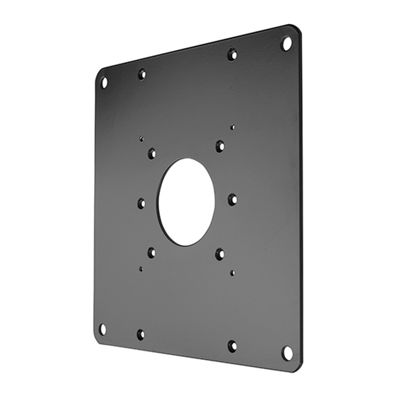
The FSB1U interface bracket is compatible with the ACCESSORY: AN ACCESSORY is the secondary Chief following VESA patterns: product which is attached to a primary Chief product, and may have a component attached or setting on it. • 75 x 75mm •... - Page 3 Installation Instructions FSB1U DIMENSIONS 8.87 225.4 18.2 MOUNTING HOLE IN BACK OF DISPLAY LONG SPACERS 11.8 SHORT SPACERS MOUNTING BUTTONS FIT INTO TEARDROP SLOTS ON MOUNT NO SPACERS 3.94 7.87 MOUNTING BUTTON & MOUNTING HOLE ARE IN LINE 8.87 225.4 3.94...
-
Page 4: Tools Required For Installation
FSB1U Installation Instructions TOOLS REQUIRED FOR INSTALLATION PARTS FSB1U Hardware Kit (Bag sections labeled A-E) CA (4) BB (4) CB (4) BA (4) CC (4) M6 x 12mm A (4) M4 x 12mm M6 x 25mm M4 x 25mm M4 x 12mm... - Page 5 Installation Instructions FSB1U INSTALLATION Recessed Mount Display Interface Installation Align and place four spacers (EA or EB) over mounting IMPORTANT ! : IMPROPER INSTALLATION CAN LEAD holes in display back. (See Figure 3) TO DISPLAY FALLING! Use only hardware provided and Align and place interface bracket assembly over four referenced within these instructions.
- Page 6 Back of display screws of the same diameter. Select correct screws, spacers (if necessary) and washers (if required) from the FSB1U hardware kit (A-EB) and partially fasten two Phillips pan head upper mounting screws (CA-EB) into interface bracket (F). (See Figure 6)
- Page 7 Installation Instructions FSB1U Align two mounting screws with upper teardrop mounting holes in Centris head. (See Figure 7) Insert two upper mounting screws into upper teardrop mounting holes in Centris head, and lower display until mounting screws are fully seated in lower area of teardrop mounting holes.
- Page 8 Europe A Franklinstraat 14, 6003 DK Weert, Netherlands P +31 (0) 495 580 852 F +31 (0) 495 580 845 Chief, a products division of Asia Pacific A Office No. 918 on 9/F, Shatin Galleria Milestone AV Technologies 18-24 Shan Mei Street...
Need help?
Do you have a question about the FSB1U and is the answer not in the manual?
Questions and answers