Kuppersbusch EKDG 6800.0 Service Manual
Combined steam ovens
Hide thumbs
Also See for EKDG 6800.0:
- Instructions for use and installation instructions (59 pages) ,
- Service manual (54 pages)

Related Manuals for Kuppersbusch EKDG 6800.0


Summary of Contents for Kuppersbusch EKDG 6800.0
- Page 1 `çãÄáåÉÇ=píÉ~ã=lîÉåë bb_a SSMMKM bad SSMMKM bhad SUMMKM bad SSMMKN bhad SUMMKN bhad SUMMKO bhad SUMMKMJ...
- Page 2 Service Manual: H3-72-01 Model Type EEBD 6600.0 EKDG 6800.0 EKDG 6800.0-75 EKDG 6800.1 EKDG 6800.2 EDG 6600.0 EDG 6600.1 Sample of a model identification plate (until 06/2007) model identification plate (from 06/2007) Model name Model name Type of variation Date of production...
-
Page 3: Table Of Contents
General ..........................6 Appliance overview ......................7 EDG 6600.1......................7 EDG 6600.0......................9 EEBD 6600.0....................... 11 EKDG 6800.0 ...................... 16 EKDG 6800.1 / EKDG 6800.2 ................20 Installation........................23 Safety instructions for technicians ............... 23 Installation EDG / EKDG ..................23 Installation EEBD 6600.0 .................. - Page 4 General information on operation and the demonstration mode......69 Demonstration mode (EDG 6600.0 and EDG 6600.1) ........69 Demonstration mode (EKDG 6800.0 and EKDG 6800.0-75) ......70 Demonstration mode (EKDG 6800.1 and EKDG 6800.2) ........70 Demonstration mode (EEBD 6600.0) ..............70 Error and alarm messages...................
-
Page 5: Safety
H3-72-01 Safety Danger! Repairs may only be carried out by a qualified electrician! Inexpert repairs may lead to risks and damages for the user! To prevent electric shocks, please observe the following tips: • In the event of faults, housing and frame may be live! •... -
Page 6: General
H3-72-01 General Depressurised steam cooking involves cooking food with a combination of steam and hot air. Gentle steam cooking at temperatures of between 40°C – 100°C optimally preserves vitamins and minerals as well as maintaining colours and natural aromas. Food does not dry out and nor will it burn or stick. Since only a relatively small amount of water needs to be heated, steam cooking means that a great deal of time and energy can be saved. -
Page 7: Appliance Overview
H3-72-01 Appliance overview EDG 6600.1 Control and display elements Supporting grid Oven temperature sensor Water tank Door seal Stainless steel baking tray Appliance door Perforated cooking pan Air vent slit Water filter (3 filters) Steam inlet 3.1.1 Control elements Operating mode Timer Adjusting knob Operating time and switch-off time... - Page 8 H3-72-01 3.1.2 Technical data Appliance dimensions Oven dimensions Niche dimensions Height 37,8 cm 25,0 cm 38,0 cm Width 54,8 cm 35,9 cm at least 58,0 cm Depth 55,1 cm 39,0 cm at least 55,0 cm Weight 47 kg Electrical connection Connection voltage 230V ~50 Hz Power...
-
Page 9: Edg 6600.0
H3-72-01 EDG 6600.0 Control and display elements Steam inlet Oven temperature sensor Supporting grid Door seal Water tank Appliance door Stainless steel baking tray Air vent slit Perforated cooking pan 3.2.1 Control elements Buttons / adjusting elements Switch-off time with a control light Operating time with a control lamp Knob... - Page 10 H3-72-01 3.2.2 Technical data Appliance dimensions Oven dimensions Niche dimensions Height 37.8 cm 25.0 cm 38.0 cm Width 54.8 cm 35.9 cm at least 58.0 cm Depth 55.1 cm 39.0 cm at least 55.0 cm Weight 47 kg Maximum load Electrical connection Connection voltage 230V ~50 Hz...
-
Page 11: Eebd 6600.0
H3-72-01 EEBD 6600.0 Appliance door Grill/top heat Door seal Oven temperature sensor Hot air blower Steam inlet Illumination Supports Oven ventilating system Socket for the food probe Accessories Food probe Water tank Roasting grid Original baking tray Stainless steel baking tray Perforated cooking pan F r i ter a use... - Page 12 H3-72-01 3.3.1 Control elements Buttons / adjusting elements Displays Illumination Temperature Operating mode using steam Time / cooking time and timer Oven/food probe temperature Operating mode without any steam Adjusting knob Timer Operating time / Switch-off time Switching off Symbols Oven temperature Time Food probe temperature...
- Page 13 H3-72-01 3.3.2 Appliance structure Floor heater Water tank 1.25 l Disc Door 1 Air temp. NTC 25°C/10kΩ 7 Water pump empty water below 80°C 8 Water pump suction 2 Protection against excessive temperatures Oven 135°C 9 Condenser water temperature 3 Temp. oven PT 500 PTC 25°C/550kΩ NTC 25°C/10kΩ...
- Page 14 H3-72-01 Heating power Hot air heater: 2.2 kW Steam generator 1.4 kW Floor heater Top heat 1.2 kW Bottom heat 1.25 kW Grill 2.5 kW Total output 3.7 kW Electric supply Connection voltage 230 V ~50 Hz or 400 V 2N ~50 Hz Connected load 3.5 kW (230 V) / 2.2 kW...
- Page 15 H3-72-01 Technical features • Clear text display with a program indicator • Climatic sensor • Limestone sensor • Permanent control of oven humidity • External steam generator • Electronic temperature control and display • Electronic timer with programmable time of day, cooking time and end of cooking time •...
-
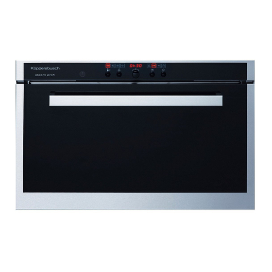
Page 16: Ekdg 6800.0
H3-72-01 EKDG 6800.0 Control and display elements Oven temperature sensor Oven ventilating system Female connector for the roast thermometer Steam inlet Rack levels Illumination Water tank Hot air blower Roast thermometer Door seal Roasting grid (2 grids) Appliance door Original baking tray made of stainless steel... - Page 17 H3-72-01 3.4.1 Control elements Buttons A ok with a control light B Illumination with a control light C Time D Timer with a control light E Switch-off time with a control light Operating time with a control light G Oven temperature H Food probe temperature with a control light Operating mode...
- Page 18 H3-72-01 3.4.2 Appliance parts Empty Suction 1 Water tank 5 Limestone sensor 2 Swivel arm 6 Hot air 3 Steam generator 7 Oven cavity 4 Steam 8 Climatic sensor 3.4.3 Technical data Appliance dimensions Oven dimensions Niche dimensions Height 37.8 cm 25.0 cm 38.0 cm Width...
- Page 19 H3-72-01 EKDG 6800.0-75 Electric connection 230~/16 A with a single phase socket system (see illustration). Due to the mains cable of 3.5 kW the appliance will need to be protected by a 16 A fuse. The appliance must be wiring as shown on the illustration.
-
Page 20: Ekdg 6800.1 / Ekdg 6800.2
H3-72-01 EKDG 6800.1 EKDG 6800.2 Control and display elements Steam inlet Oven ventilating system Female connector for the roast thermometer Illumination Supporting grids Hot air blower Water tank Door seal Food probe Appliance door Roasting grid (2 grids) Air vent slit Stainless steel baking tray Oven temperature sensor Perforated cooking pan... - Page 21 H3-72-01 3.5.1 Control elements Buttons / adjusting elements Displays Illumination Clear text display Oven/food probe temperature Temperature Operating mode Time / cooking time and timer Adjusting knob Draught eye Timer Operating time / Switch-off time Switching off Symbols Oven temperature Operating time Food probe temperature Switch-off time...
- Page 22 H3-72-01 3.5.2 Appliance parts Emptying Suction 1 Water tank 5 Limestone sensor 2 Swivel arm 6 Hot air 3 Steam generator 7 Oven cavity 4 Steam 8 Climatic sensor 3.5.3 Technical data Appliance dimensions Oven dimensions Niche dimensions Height 37.8 cm 25.0 cm 38.0 cm Width...
-
Page 23: Installation
H3-72-01 I sta ati Safety i structi s f r tech icia s • Local electricity suppliers’ statutory regulations and conditions for connection are to be fully observed. • The appliance must be disconnected on being connected, on carrying out repairs and when changing a bulb. - Page 24 H3-72-01 in a standard niche (with a levelling panel, ZUB. 736 (in preparation) 4.2.2 in kitchen units Installing the appliance • Put the plug into the socket. • If “U2” is indicated on the display, the plug must be turned. Should this not be possible, a qualified electrician must exchange the zero conductor and the terminal wire in the socket.
-
Page 25: Installation Eebd 6600.0
H3-72-01 Installation EEBD 6600.0 4.3.1 in a suitable niche Fitted installation Niche Installation 5/6 niche SMS 4 Electric connection cable 5 Adapter frame Niche 4.3.2 in kitchen units Installing the appliance • Put the plug into the socket. • If “U2” is indicated on the display, the plug must be turned. - Page 26 H3-72-01 Open the snap fastener of the strain relief with a screwdriver. 550 Niche 548 Appliance Appliance Niche Model identification plate Electric connection cable Exhaust air position Adapter frame Appliance door open Push the appliance up to approx. 19 cm into the niche. Caution! Risk of tipping over! Open the terminal box with the screw and swing it down.
- Page 27 H3-72-01 4.3.4 Combined connection Important! When connecting a second appliance (e.g. a cooking zone) the electrical supply line must be dimensioned accordingly and protected by fuse. Observe installation norm DIN! When connecting a second appliance the connection cable of this appliance must be guided separately into the opening D2 and must be secured with strain relief E2.
-
Page 28: Edg / Ekdg Appliance Components
H3-72-01 EDG / EKDG appliance components Limestone sensor Limestone sensor and heat protection NTC 25°C/10 kW Heater installed Heater with limestone Heater dismounted The amount of scaling is determined as two measured variables, namely the temperature of the heating spiral and the conductance of the level sensor. Scaling on the tubular heating element of the evaporator increases the readings taken on the heating spiral temperature sensor. -
Page 29: Water System
H3-72-01 Water system Water tank, 1.25 litres Ignition solenoid F r i ter a use... - Page 30 H3-72-01 5.3.1 Water inlet If, during a certain period, no water is recognised in the evaporator on filling, the supply of water is discontinued and the clear text display will indicate “Fill up with water”. The following may be the cause of a faulty water supply: •...
-
Page 31: Automatic Altitude Adjustment
H3-72-01 Automatic altitude adjustment Sensor for altitude adjustment and water NTC 25°C/100 kΩ Altitude adjustment is carried out automatically for the steaming, regenerating, baking like professionals and hot air with steam vapour modes. Automatic altitude adjustment enables the hot air temperature to be regulated with some difference in temperature below the maximum possible steaming temperature. -
Page 32: Floor Heater 140 W With Protection Against An Excessive Rise In Temperature
H3-72-01 Floor heater 140 W with protection against an excessive rise in temperature Excessive temperature Excessive temperature Excessive temperature Floor heater The floor heater serves the purpose of reducing the quantity of condensate on the floor of the oven. The quantity of water required during the cooking process can also be reduced by means of repeated evaporation. -
Page 33: Recognising A Steam Leak With The Climatic Sensor
H3-72-01 Recognising a steam leak with the climatic sensor Climatic sensor Leaks, such as those caused by damaged or dirty door sealing, insufficient sealing of the hot air motor shaft, open vent flaps, blocked steam emissions, climatic sensors which are full of water or anything similar, will distort the temperature reading of the climatic sensor. -
Page 34: Slide With A Magnetic Lifting Cylinder
H3-72-01 Slide with a magnetic lifting cylinder Please note! On steaming, inlet air and outgoing air of the oven are closed. 12 V transformer for the water Protection against an pump (return) excessive rise in oven temperature PT 500 Transformer Excessive rise in temperature print K2.8310... -
Page 35: Electric Connecting Box
H3-72-01 Electric connecting box Breakdown In the event of a breakdown, for example, on opening the door, settings such as operational mode, oven temperature and core temperature, operating time and switch-off time are maintained. Timing comes to a halt. Hot air with Baking like Breakdown Symptom... -
Page 36: Appliance Components: Eebd 6600.0
H3-72-01 Appliance components: EEBD 6600.0 Water tank switch Operating element Water tank Reed switch for the door Inlet valve Climatic sensor Water level pin Cross-current fan Food probe Exhaust air slide Evaporator Top heat / grill NTC water temperature Pt 500 thermostat Evaporator heater Computer Discharge pump... -
Page 37: Water Tank Microswitch
H3-72-01 Water tank microswitch Microswitch Cross-current fan for the cooling air F r i ter a use... -
Page 38: Revolution Counter For The Cross-Current Fan
H3-72-01 Revolution counter for the cross-current fan Number of revolutions Cooling air fan (photo cell) Removing the air system When mounting, care must be taken that the slide of the steam ascending pipe and the climatic sensor are retracted properly in order to avoid leaking steam. F r i ter a use... -
Page 39: Door Switch (Reed Contact)
H3-72-01 Door switch (reed contact) Reed contact Discharge pump with a filter for “dynamic filtering” Bottom heat inner / outer circuit F r i ter a use... -
Page 40: Protection Against Excessive Temperatures 2 X 280°C
H3-72-01 Protection against excessive temperatures 2 x 280°C Protection against excessive temperatures Replacing a Pt 500 sensor seal The Pt 500 sensor seal can be mounted very carefully from the front. (caution: do not damage the seal). If this is not carried out successfully, the entire rear wall support panel will need to be removed with the side wall. -
Page 41: Complete Evaporator 1400 W / 230 V
H3-72-01 6.10 Complete evaporator 1400 W / 230 V Heater Evaporator 6.11 Climatic sensor 6.12 Drive (step motor) / exhaust air slide Drive Exhaust air slide F r i ter a use... -
Page 42: Water Tank
H3-72-01 Extend the step motor with a gear wheel 6.13 Water tank The water tank must be inserted until it stops (A)! • The water tank is concealed behind the swivel door. • 1.25 litre capacity („MAX 1.25 l“ marking for fresh cold tap water). •... -
Page 43: Water Intake / Water Discharge
H3-72-01 6.14 Water intake / water discharge Heater Valve for intake Pump for discharge Evaporator Evaporator Evaporator F r i ter a use... -
Page 44: Solenoid Valve
H3-72-01 6.15 Solenoid valve The force of gravity will cause the water to flow to the discharge pump. OPEN CLOSE 6.16 Building up steam in the evaporator (heater activated) Heater Valve for intake Pump for discharge Evaporator Evaporator Evaporator F r i ter a use... - Page 45 H3-72-01 Supplying steam to the oven Water is filled up or fed into the steam tank! Why this difference? Feeding water in the steam tank: The amount of water is always maintained at the same level and the heater remains in operation! Filling the steam tank up with water: The heater is switched off, the solenoid valve is opened, and...
- Page 46 H3-72-01 Example: Steam heating mode Hot air heater Supports the heating phase Bottom heat (inside) is only used briefly to pre- heat the oven muffle! F r i ter a use...
-
Page 47: Operational Modes
Operational modes The operation modes are sub-divided into various procedures. Each procedure comprises several steps during which the functions are activated with one or several commands. The operating modes are distinguished as follows: Top/ Baking like Hot air with Pizza Slow Procedure Steaming... -
Page 48: Steaming
H3-72-01 Steaming Recommended oven temperature: 100 °C (equivalent to the maximum possible boiling temperature) Area of application: 30 °C to 100 °C During the steaming mode, steam flows into the oven from an external steam generator. At the same time hot air facilitates the heating up process of the appliance. The steam operational mode is suitable for: •... - Page 49 H3-72-01 Heating with hot air and steam / continued steam heating Subsequent to altitude adjustment, the hot air heater will be switched on. When the hot air heater is switched on, the power of the evaporator heater is reduced in order not to exceed the fuse-protected power supply of the single-phase appliance connection.
- Page 50 H3-72-01 Emptying is carryied out with a maximum time limit from water level recognition on, plus a certain follow-on time. • Subsequent to emptying “residual heat” is indicated in the clear text display above a certain oven temperature. For the legend, see page 68 7.1.2 Sequence diagram: Steaming (EDG - EKDG) F r i ter a use...
- Page 51 H3-72-01 7.1.3 Sequence diagram: Steaming (EEBD 6600.0) F r i ter a use...
-
Page 52: Regenerating
H3-72-01 Regenerating Recommended oven temperature: 130°C Area of application: 100°C to 150°C On regeneration, the oven is heated with steam and hot air. This ensures fast, consistent heating up of the food without any drying out. The regeneration operational mode is suitable for: •... - Page 53 H3-72-01 Sequence diagram: Regenerating (EDG - EKDG) F r i ter a use...
- Page 54 H3-72-01 7.2.2 Sequence diagram: Regenerating (EEBD 6600.0) F r i ter a use...
-
Page 55: Baking Like Professionals
H3-72-01 Ba i g i e pr fessi Recommended oven temperature: 210°C Area of application: 100°C to 230°C During the baking like professionals mode the food is firstly vaporised in an initial phase and operation is then automatically adjusted for the second “hot air phase” subsequent to a steaming period which depends on the quantity of food in the oven. - Page 56 H3-72-01 Continued heating with hot air (hot air phase) The hot air phase commences after the steam phase. The heater in the evaporator is switched off. The heater remains switched on at full power until the T pre-set oven temperature or given oven temperature is reached.
- Page 57 H3-72-01 Sequence diagram: Baking like professionals (EDG - EKDG) F r i ter a use...
- Page 58 H3-72-01 7.3.2 Sequence diagram: Baking like professionals (EEBD 6600.0) F r i ter a use...
-
Page 59: Hot Air
H3-72-01 Hot air Recommended oven temperature: 180°C Area of application: 30°C to 230°C On heating with hot air, the air in the oven is heated up by a heater located behind the back wall of the oven and is then circulated evenly throughout the oven by means of the hot air fan. The baked products are therefore heated up from all sides, enabling simultaneous baking at two or three levels. - Page 60 H3-72-01 7.4.2 Sequence diagram: hot air (EEBD 6600.0) Proposed oven temperature: 180°C Application: 30°C to 230°C The distribution of hot air is “less sensitive” if an unsuitable rack level is selected. F r i ter a use...
- Page 61 H3-72-01 7.4.3 Sequence diagram: hot air moist (EEBD 6600.0) Proposed oven temperature: 180°C Application: 30°C to 230°C Suitable for: gratins, oven bakes and yeast dough products F r i ter a use...
-
Page 62: Hot Air With Steam Vapours (Eebd 6600.0)
H3-72-01 Hot air with steam vapours (EEBD 6600.0) Recommended oven temperature: 180°C Area of application: 30°C to 230°C On heating with hot air, the air in the oven is heated up by a heater located behind the back wall of the oven and is then circulated evenly throughout the oven by means of the hot air fan. - Page 63 H3-72-01 Should vapourisation not be activated, the heater in the evaporator will be switched off. The heater will only be switched on again once the water in the evaporator has fallen below a certain temperature. The water temperature in the evaporator is then maintained at this standby level. Steam dissipation Steam dissipation is only carried out if the climatic sensor has been actuated at a certain point in time prior to completion of cooking (see “5.
-
Page 64: Grill (Eebd 6600.0)
H3-72-01 Grill (EEBD 6600.0) 7.6.1 Sequence diagram: Grill Large-surface grill Proposed oven temperature: 230°C Application: 200°C to 230°C F r i ter a use... -
Page 65: Pizza Plus (Eebd 6600.0)
H3-72-01 Pizza Plus (EEBD 6600.0) 7.7.1 Sequence diagram: Pizza Plus Proposed oven temperature: 180°C Application: 30°C to 230°C F r i ter a use... -
Page 66: Slow Cooking (Eebd 6600.0)
H3-72-01 Slow cooking (EEBD 6600.0) 7.8.1 Sequence diagram: slow cooking (gently roasted) Strong heating phase Proposed core temperature: 70°C Adjustable duration: 2.5 – 4.5 hours F r i ter a use... -
Page 67: Top / Bottom Heat (Eebd 6600.0)
H3-72-01 Top / bottom heat (EEBD 6600.0) 7.9.1 Sequence diagram: Top / bottom heat Proposed oven temperature: 180°C Application: 30°C to 230°C External bottom heat • No influence on the baking time • Slightly longer heating up time: Rapid heating up in approx. 6 minutes Normal heating up in approx. -
Page 68: Legend
H3-72-01 7.10 Legend Ablaufpumpe discharge pump Abluft exhaust air Abluft-Schieber exhaust air slide Bodenheizung floor heater Dampf steam Drehzahlstufe speed level Einschaltdauer operation time Entkalken descale erstes Ansprechen Klimasensor initial activation of the air sensor geschlossen closed Heissluft hot air Heizkörper heater HL Ventilator... -
Page 69: General Information On Operation And The Demonstration Mode
H3-72-01 General information on operation and the demonstration mode Operation: EEBD 6600.0 The operation modes, the oven temperature and the core temperature as well as the duration of cooking time and various other functions may be selected by touching the respective button once or several times. -
Page 70: Demonstration Mode (Ekdg 6800.0 And Ekdg 6800.0-75)
H3-72-01 Demonstration mode (EKDG 6800.0 EKDG 6800.0-75) Requirement: The appliance must be ready for operation before it is switched on or off, i.e. all of the displays are dark apart from the time of day display. Switching the appliance on and off: Keep the OVEN LIGHTING buttons pressedi and then also press the TIME OF DAY, TIMER, OPERATING TIME and SWITCH-OFF TIME buttons. -
Page 71: Error And Alarm Messages
The EKDG 6800.0 only has one A-alarm message, which can only occur at the end of a procedure and which is indicated by means of the text “Boiler scaled. -
Page 72: Overview Of Reference Messages
H3-72-01 Depending on the cause of the fault, there are two principle possibilities to reset: resetable: Users can acknowledge the fault message by pressing a button. If there is still reason for the fault, there will be a renewed fault indication, either immediately or during the next program. -
Page 73: Schedule Of H-Fault Messages (Only Eebd And Edg)
H3-72-01 Schedule of H-fault messages (only EEBD and EDG) Fault Description EEBD Description EDG Water tank switching contact Water tank switching contact Level pin faulty Level pin faulty Door switching contact Door switching contact Food sensor switching contact No descale actuation acknowledgement Filling time exceeded Slow cooking discontinued H 10... -
Page 74: Fault Schedule (Edg 6600.0 And Edg 6600.1)
H3-72-01 Fault schedule (EDG 6600.0 6600.1) Signal Faulty diagnosis of the micro- Possible causes of the fault controller Water tank contact is In addition to the fact that there is no water tank the following may open be the cause: 1. -
Page 75: Fault Schedule Ekdg 6800.0
The mode intended for exhibition purposes. No heaters are (message only appears after a power cut) switched on and no error messages are given. Fault schedule EKDG 6800.0 Signal Faulty diagnosis of the micro- Possible causes of the fault controller... - Page 76 H3-72-01 Data backup faulty (EEPROM) 1. Calculator defect (component faulty, EMC influences, moisture, dirt, etc.). Water temperature does not rise 1. Evaporator heater defect (excessive temperature cut-off device) sufficiently (when the evaporator 2. Faulty wiring (plug connections, interruption, short circuit, loose heater is activated the water tempera- contact, etc.) ture does not rise sufficiently)
-
Page 77: Fault Schedule Ekdg 6800.1
H3-72-01 Fault schedule EKDG 6800.1 Signal Faulty diagnosis of the micro- Possible causes of the fault controller Add water Water resistance remains high although Besides a lack of water in the tank, the following may also be the the pump is switched on (level pin does cause: not conduct). - Page 78 H3-72-01 Emptying function faulty (the level pin 1. Discharge pump does not transport sufficiently (swivel arm/ does not develop sufficient high resist- hose blocked or crushed). ance when water is pumped out) 2. Wiring to the level pin short circuited 3.
-
Page 79: Fault Schedule Ekdg 6800.2
H3-72-01 Fault schedule EKDG 6800.2 Signal Faulty diagnosis of the micro- Possible causes of the fault controller Add water Water resistance remains high Besides a lack of water in the tank, the following may also be the although the pump is switched on cause: (level pin does not conduct). - Page 80 H3-72-01 Water temperature does not rise 1. Heater defect, flange interruption (protection against excessive sufficiently (the water temperature temperatures) does not rise sufficiently when the 2. Faulty wiring (plug connections, interruption, short circuit, loose evaporator heater is activated) contact, etc.) 3.
-
Page 81: Fault Schedule Ekdg 6800.0-75
H3-72-01 Fault schedule EKDG 6800.0-75 Faulty diagnosis of the micro- Signal Possible causes of the fault controller Add water Water resistance remains high although Besides a lack of water in the tank, the following may also be the pump is switched on (level pin does not the cause: conduct). -
Page 82: Fault Schedule: Eebd 6600.0
H3-72-01 Faulty diagnosis of the micro- Signal Possible causes of the fault controller Air temperature does not rise sufficiently. 1. Too much cold food put into the oven (for steaming a max. of 2 kg frozen food allowed). 2. Exhaust air slider/motor stuck or defect (in the case of initial series appliances with a rated frequency of below 300, replace the calculator too;... - Page 83 H3-72-01 Besides normal scaling on the evaporator the following may be the H 10 Descale instruction cause: Number of hours of operation of 1. Water intake blocked or limescaled the evaporator heater reached 2. Intake valve jammed Hose crushed Level pin dirty: The pin only devel- ops low resistance on filling up 3.
- Page 84 H3-72-01 Rise in air temperature faulty (when 1. Oven leaks (loss of steam, exhaust air slider leaks, food sensor the evaporator heater is activated the socket defect, doors not closed properly?) air temperature rises too slowly) 2. Air temperature sensor does not react. Probe dirty/wet 3.
- Page 85 H3-72-01 F 22 Water intake faulty Intake valve leaks (valve leak, limestone chips in the gasket, etc.) No supply of water during steam oper- ation (independent operation time of the evaporator heater within the filling time) On the PE terminal of the combined mains connection the PE earth PE mains connection faulty wire or a terminal wire has been connected to terminal N (400V Controls functioning, but the mains...
-
Page 86: Wrong Behaviour
H3-72-01 Wrong behaviour 10.0.1 Oven temperature sensor PT 500 The oven temperature recording is monitored for short circuits and interruptions in the sensor and in the reference resistance. In the case of a malfunction, an error is indicated. RESISTANCE DEPENDING ON THE Oven temperature PT 500 TEMPERATURE Temperature (°C) -
Page 87: Food Temperature Sensor
H3-72-01 10.1 Food temperature sensor RESISTANCE SEQUENCE (°C) (kΩ) (± %) (± %) 50,0 40.3 32.7 26.6 21.9 18.0 14.9 12.4 10.4 8.76 7.40 6.28 5.35 4.58 3.93 3.39 Fault mechanisms ≤ As soon as the output voltage of the temperature sensor wiring is below approx. 0.07 V (binary data ≥... -
Page 88: Water Temperature Sensor
H3-72-01 1) It is absolutely essential that the sensor casing (connection 2) be earthed, depending on the safety category of the electronics system connected. 2) Definition “thermal time control”: response time to 63°C (0 - 63% of the terminal value) in the case of a sudden change in temperature from 25 to 85°C, sensor fully immersed in liquid (in this case 50 mm test immersion depth). -
Page 89: Heating Spiral Sensor And Steam Temperature Sensor
H3-72-01 In the event of a fault, the appliance control system switches off all of the actuators and switches over to fault mode. The fault can be acknowledged with any button. It will, however, re-occur if the cause of the fault is not rectified. -
Page 90: Boiler Heater
H3-72-01 10.5 Boiler heater When the boiler heater is switched on the water temperature is monitored during the process of altitude adjustment. A fault is indicated if the water temperature no longer rises and if it has not reached a certain level within a stipulated period of time. The boiler heater is checked during altitude adjustment, which is carried out prior to each respective steaming phase. -
Page 91: Emptying
H3-72-01 Please note! The process of emptying is influenced by water level measurement limiting values stipulated in the EEPROM data storage. 10.7 Emptying The maximum pumping off time during the process of emptying is monitored. If, after a certain period of time, the water level pin still detects water, a fault will be indicated. -
Page 92: Boiler And Water Level Pin Scaled
H3-72-01 10.8 Boiler and water level pin scaled Fault mechanism Scaling of the boiler is detected during the process of altitude adjustment. If the difference between the temperatures of the heating spiral and the water, taken with several measurements, is too great, or if the water level pin has been recognized as being scaled several times, an alarm message will be indicated. -
Page 93: Water Tank Leaks (Eebd 6600.0)
H3-72-01 10.10 Water tank leaks (EEBD 6600.0) If the water tank connection to the solenoid valve has a leak the water will flow through the air channel where it can evaporate with the outgoing air or…. Evaporation ... water flows through the air channel and can then evaporate with the outgoing air or it can flow into the oven muffle (steam ascending pipe and climatic sensor). -
Page 94: Descale
H3-72-01 Descale 11.1 EDG and EKDG Program duration: approx. 35 minutes The “descale” program can be selected with the OK button (menu of the OK button back – user settings – descale). Application Descaling comprises the following steps: • The water tank, which is filled with 0.5 litres of a mixture of equal proportions of descaling agent and water, is recognised. -
Page 95: Eebd 6600.0
H3-72-01 • The process of descaling is only completed when the water tank is removed after two rinsing phases have been fully implemented. In the event of a power cut during the descaling process, the descaling program will be repeated or will continue with operation from the procedure step (Descale, 1. - Page 96 H3-72-01 This will give rise to error patterns: • The “boiler limescaled” instruction appears even though a descaling process was carried out only recently • The discharge pump is reported as being defect • No water is pumped through, the evaporator runs dry, becomes overheated and the Klixon switches off (in the worst case the heater will burn - error code: F7) Replacing the operating element, the discharge pump, etc., will not have any effect.
-
Page 97: Flow Chart: Descaling Programme (Eebd 6600.0)
H3-72-01 11.3 Flow chart: Descaling programme (EEBD 6600.0) F r i ter a use...
Need help?
Do you have a question about the EKDG 6800.0 and is the answer not in the manual?
Questions and answers