CHIEF SLMU Installation Instructions Manual
Universal
Hide thumbs
Also See for SLMU:
- Installation instructions manual (25 pages) ,
- Installation instructions manual (8 pages) ,
- Installation instructions manual (8 pages)
Table of Contents
Advertisement
Quick Links
I N S T A L L A T I O N
UNIVERSAL INTERFACE BRACKETS
The Universal Interface Bracket provides a solution for
simplifying inventory of RPA and RPM series mounts
and SLB/SLM projector brackets.
This bracket allows for exact alignment with the
projector. The projector can be shifted around on the
mounting plate until its weight is centered and balanced.
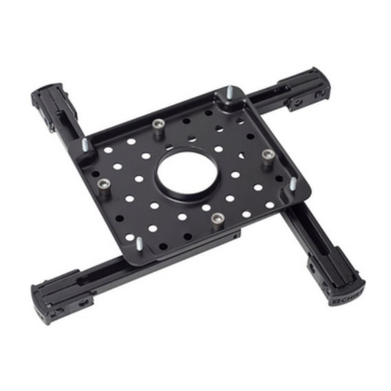
The SLBU/SLMU is equipped with adjustable legs and
feet, which can be moved to any angle, depending on the
mounting-hole pattern on the projector. Leg and foot
length, width, and height can readily be adjusted.
The SLBU/SLMU is shipped with All-Points™ Security
System hardware, which is designed to protect projectors
from theft. Chief Manufacturing provides the security kit
exclusively.
BEFORE YOU BEGIN
CAUTION: To prevent damage to your monitor, which could affect or void the Factory warranty,
thoroughly study all instructions and illustrations before you begin to install the mount brackets. Pay
particular attention to the Warnings and Cautions in this document.
If you have any questions about this installation, contact Chief Manufacturing at 1-800-582-6480 or 952-582-6480.
SLBU / SLMU
CHIEF MANUFACTURING INC.
1-800-582-6480 952-894-6280 FAX 952-894-6918
8401 EAGLE CREEK PARKWAY, STE. 700
SAVAGE, MINNESOTA 55378 USA
I N S T R U C T I O N S
SLBU
SLMU
8802-000166 (Rev H)
2007 Chief Manufacturing
www.chiefmfg.com
12/07
Advertisement
Table of Contents

Related Manuals for CHIEF SLMU


Summary of Contents for CHIEF SLMU
- Page 1 Pay particular attention to the Warnings and Cautions in this document. If you have any questions about this installation, contact Chief Manufacturing at 1-800-582-6480 or 952-582-6480. CHIEF MANUFACTURING INC.
-
Page 2: Tools Required For Installation
Installation Instructions SLBU/SLMU IMPORTANT WARNINGS and CAUTIONS! WARNING A WARNING alerts you to the possibility of serious injury or death if you do not follow the instructions. A CAUTION alerts you to the possibility of damage or destruction of equipment if you do not follow CAUTION the corresponding instructions. -
Page 3: Table Of Contents
(70) Adjusting the Legs on Bracket........6 M5 x 12mm Phillips Pan Head Screw Aligning the SLBU/SLMU (as shipped) on a Projector with 4 Mounting Holes ........ 6 M4 x 10mm Phillips Aligning the SLBU/SLMU (minus 1 adjustable leg) Pan Head Screw on a Projector with 3 Mounting Holes ...... -
Page 4: Parts
Installation Instructions SLBU/SLMU PARTS Figure 1. SLBU Assembly Figure 2. SLMU Assembly 90 (SLBU Only) Figure 3. Mounting Hardware Kit Figure 4. Direct Mounting (without foot brackets) -
Page 5: Installation Instructions
Installation Instructions SLBU/SLMU INSTALLATION INSTRUCTIONS STEP 1 (Optional) Measuring the Mounting Hole Dimensions On the Projector To minimize error, perform the following steps to measure the approximate width and length between the mounting holes on your projector. 1. Determine the width and length between the mounting holes on your projector. -
Page 6: Adjusting The Legs On Bracket
The mounting holes on projectors are supplied in a a. Place the SLBU/SLMU (10) on your projector. variety of different patterns. There is no standard b. Adjust the legs on the SLBU/SLMU (10) as mounting-hole configuration pattern for projectors. needed. Align the adjustable legs on the... -
Page 7: Projector With 3 Mounting Holes
Screw hole pattern on the projector. bracket. 4. Align the SLBU/SLMU on the projector, as follows: a. Place the SLBU/SLMU (10) on your projector. Hex nut b. Adjust the legs on the SLBU/SLMU (10) as needed. Align the adjustable feet on the Figure 8. -
Page 8: Projector With 3 Mounting Holes
Install adjustable leg 5. Align the SLBU/SLMU on the projector, as follows: in horizontal slot. a. Place the SLBU/SLMU (10) on your projector. Figure 9. Align the SLBU/SLMU on 3-Hole Projector b. -
Page 9: Aligning The Slbu/Slmu On A Projector Using Direct Mounting Option
NOTE: Keep unused adjustable foot brackets and attaching hardware in a safe for future use. 3. Align the SLBU/SLMU on the projector, as follows: a. Place the SLBU/SLMU (10) on your projector. b. Adjust the legs on the SLBU/SLMU (10) as Figure 11. -
Page 10: Adjusting Foot Height On Slb-U
STEP 3 Level the RPA/RPM/ Adjusting Foot Height on Bracket Mounting Adjust the feet on the SLBU/SLMU for height, as Plate follows: NOTE: Foot height is adjusted for a variety of reasons, which includes, but is not limited to, ventilation, uneven projector surface, and to level the RPA/RPM/RPM mounting plate. - Page 11 Installation Instructions SLBU/SLMU...
- Page 12 Installation Instructions SLBU/SLMU...
Need help?
Do you have a question about the SLMU and is the answer not in the manual?
Questions and answers