Table of Contents
Advertisement
Advertisement
Table of Contents

Related Manuals for Sam4s 110 Series


Summary of Contents for Sam4s 110 Series
-
Page 2: Table Of Contents
Table of Contents UEFI BIOS Set Up System Introduction Appendix A Part 1 1. Safety Notices Before Installation or Use 1. Understanding BIOS 2. System Introduction • Understanding BIOS Set up 3. General Specifications 2. Serial voltage change & Using Keyboard shortcut 4. - Page 3 1. Cautions for safety before installation and use • Use the following safety guidelines to help ensure your own personal safety and to help protect your equipment and working environment from potential damage System should use compatible peripherals. Devices other than peripherals provided by us may experience compatibility issues.
- Page 4 1. Cautions for safety before installation and use • Use the following safety guidelines to help ensure your own personal safety and to help protect your equipment and working environment from potential damage Connect the AC code to the grounded outlet. Do not use the damaged power cable as there may be fire and electric shock hazard of electric shock.
-
Page 5: Part 1 System Introduction
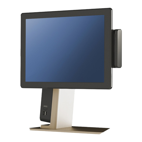
System Introduction Part 1 2. System Introduction • The exterior design and specifications of product can be changed without prior notice in order to improve quality. Keybord Mouse, Pad Manual Adapter, Cable... -
Page 6: General Specifications
System Introduction Part 1 3. General Specifications Intel Celeron J1900 2.0GHz(2M Cache, up to 2.42GHz) Processor Intel Core-i3 7100U 2.40GHz(3M Cache) Intel Core-i5 7200U 2.5GHz(3M Cache, up to 3.10GHz) Chipset Graphic Integrated Intel HD Graphics SATA-III 2.5” SSD/HDD, m.2 2280 SSD Data Storage RAID Supported (Option) J1900 : DDR3 1600MHz 1 Slot (up to 8GB) -
Page 7: Optional Specifications
System Introduction Part 1 4. Optional Specifications Option 1 ) SERIAL 1+1 D-SUB 9P x 1Port / RJ-45 x 1Port External I/O Interface Option 2) USB 2x2 USB 2.0 x 4Ports Option 3 ) Parallel Parallel x 1Port Read Track : ISO track 1, 2, 3 Interface : Internal USB Performance : 10~150 cm/sec Magnetic Swipe Reader(MSR) Head Reliability : 500,000 times... -
Page 8: Name And Function Of Each Component Front View
System Introduction Part 1 5. Name and Function of each component Front View 1. USB 2.0 Port USB Devices can be used through this port, i.e. USB Scanner, USB Keyboard, USB Printer, etc. 2. Power button System power on and off through this button. 3. -
Page 9: Name And Function Of Each Component Rear View
System Introduction Part 1 6. Name and Function of each component Rear View 1. Screw Hole Fix a card reader. 2. Push Button for detachable Main Display 3. Upper Cover of Stand Remove this cover, you can replace storage or install customer display. System Cover Remove this cover, you can connect peripheral devices. - Page 10 System Introduction Part 1 7. Name and Function of each component 1. System Main Board 2. 2.5” SATAIII Storage (SSD/HDD) 3. Bridge board Connecting Main board and I/O module 4. I/O Module Connection peripheral devices 5. LVDS or eDP Cable Display cable for Main display...
-
Page 11: Name And Function Of Each Component I/O
System Installation Part 2 7. Name and Function of each component I/O 2 -2 2 -1 1. RJ-45 LAN (ETHERNET) port You can connect RJ45 cable for 100M/1Gbps Ethernet connection 2. USB port You can connect devices such as the USB scanner, USB keyboard, USB printer. J1900 System support USB 2.0, Core-i3/i5 System supports USB 3.0. - Page 12 System Installation Part 2 8. Name and Function of each component Extended I/O FORZA supports 3 types of extended I/O module. (USB/RS-232/Parallel) 1 - 1 RJ-45 8Pin COM(Serial) port 1-1. You can connect serial devices such as barcode scanners, printers. 1 - 2 1-2.
-
Page 13: Checking The Location For Installation
System Installation Part 2 1. Checking the Location for Installation It is important to choose a safe and secure place to install the terminal. Refer the information below. Choose a desk or table big and strong enough to support the weight of the system and peripherals. - Page 14 System Installation Part 2 1. Checking the Location for Installation It is important to choose a safe and secure place to install the terminal. Refer the information below. • How to adjust monitor Adjust the system depending on the condition and use it with the exact angle. Adjustable angle shown in the figure •...
-
Page 15: Before Connecting Peripherals
System Installation Part 2 2. Before Connecting Peripherals To connect peripherals first remove ‘System Cover’, which is the side of the system. • Turn off the power of the system and connect/disconnect peripherals. • Connecting peripherals to the corners parts of the system can cause hands injury. -
Page 16: Connecting Dc Power Supply Cable
System Installation Part 2 3. Connecting DC power supply Connect the DC power cable to the DC power input connector at the side of the system. (Adapter 100V – 220V free voltage of the system can be used.) • Only manufacturer adapter should be used for this system. •... -
Page 17: System Utilization
System Utilization Part 3 1. Touch Screen Use During the use of touch screen, when the accuracy becomes an issue, please re-do coordination adjustment. 1. Right click on the icon located at the lower right corner of menu and click on Control Panel. Icon 2. -
Page 18: Using The Touch Screen
System Utilization Part 3 1. Using the Touch Screen • Do not use sharp objects such as pen as it may damage surface of the display. 4. Click on the Standard Calibration button to start calibration. A green box will appear. Hold on the point for couple seconds. - Page 19 Adobe Reader 11.0 : The Adobe Reader program is inside the folder. MiiniPrinter : The windows driver for SAM4S mini printer ELLIX series is inside the folder. MS Excel Viewer : The Microsoft excel viewer program is inside the folder.
- Page 20 System Utilization Part 3 2. Introducing POS System Driver and Utility Drawer Driver : Cash Drawer Driver Installation file is inside the folder. MSR : MSR Setup file is inside the folder. OPOS : OPOS driver installation file is inside the folder. Self Test Program : Test programs for dealers are inside the folder.
- Page 21 System Utilization Part 3 3. Using Dual Monitor Forza supports both DP and HDMI and therefore, additional external display can be connected for usage. (Only the system with i3 and i5 CPU supports HDMI port.) Dual monitor setting is documented based on the Windows 10. How to Use Dual Display The function of dual display is using two monitor in one system to show the same screen (Clone) or to extend the monitor screen side (Extend).
- Page 22 System Utilization Part 3 3. Using Dual Monitor 4. At display setting window, set display list (S) as 1┃2 multiple display and multi display list (M) as duplicate these display. (in this case, the dual monitor will show the duplicated screen.) 5.
- Page 23 System Utilization Part 3 4. Using Dual Monitor • How to confirm on dual monitor If the dual monitor function does not function properly, please refer to below approaches for resetting. Approach 1 • From BIOS set up, check that the Chipset ▶ North Bridge ▶ LCD Control ▶ Boot Display Device list s are set as LVDS.
- Page 24 System Utilization Part 3 4. Using Dual Display Touch Screen When using expansion mode on touch type dual display, please follow below steps. (Supporting OS : POSReady7, Window 7, 8.1, 10 (IoT) 1. Right-mouse click on the icon at the bottom right of Window screen and click on Control Panel from the menu.
- Page 25 System Utilization Part 3 4. Using Dual Display Touch Screen When using expansion mode on touch type dual display, please follow below steps. (Supporting OS : POSReady7, Window 7, 8.1, 10 (IoT)) 4. From Display Option, select the first main monitor and click on Setup. 5.
-
Page 26: How To Control Direct I/O In Order To Use Drawer
System Utilization Part 3 5. How to control Direct I/O in order to use cash drawer It is HEXA information of the commend for control cash drawer. User can refer for programming. It is possible to control 2 drawers at a same time through 1 port. I/O address to open or close Drawer 0xA04 Kick out... -
Page 27: System Extension & Disassemble
System Extension & Disassemble Part 4 Power Adaptor Confirm that the power of peripherals and systems are turned off. Push & Pull the System Cover in the direction of the arrow to disassemble. Disconnect the DC power supply and other cable of peripherals. •... -
Page 28: Line Display
System Extension & Disassemble Part 4 2. 2 Line Display 1. Operating Voltage of 2 Lind Display is 5V. you can refer to Appendix A. BIOS Set up – 02. Serial voltage change & Using Keyboard shortcut to set the Voltage of COM4 •... - Page 29 System Extension & Disassemble Part 4 6. Connect Serial Cable to COM4 as below picture. RJ-45 8pin Serial (COM4) • Please be aware of not connecting to LAN port. System will be damaged. 7. Assemble the Upper Case for Dual Display which is enclosed herewith 2 Lind Display 8.
-
Page 30: Dual Display
System Extension & Disassemble Part 4 3. Dual Display * Assemble & Disassemble structure is same for 9.7”, 15” 10.1” and 15.6” Dual Display. 1. Proceed same up to No.3 of 2. 2 Lind Display 2. Screw the Cable Clamp which is enclosed herewith Dual Display 3. - Page 31 System Extension & Disassemble Part 4 1. FCD-100(9.7”) is mounted 2. FCD-150(15”) is mounted 3. 2 Lind Display is mounted 4. FCD-101(10.1”) is mounted...
-
Page 32: Magnetic Card Reader
System Extension & Disassemble Part 4 4. Magnetic Card Reader 1. Unfasten 2 screws of Magnetic Card Reader to disassemble... - Page 33 System Extension & Disassemble Part 4 5. 2.5” SSD / HDD 1. Confirm that the power of peripherals and systems are turned off. 2. Disassemble Upper Case 3. Pull 2.5” SSD(or HDD) to disassemble. assemble and confirmation of it working 1.
-
Page 34: Basic I/O Module
System Extension & Disassemble Part 4 6. Basic I/O Module 1. Confirm that the power of peripherals and systems are turned off. 2. Push & Pull the System Cover in the direction of the arrow to disassemble. 3. Remove Power Adapter and Cables 4. -
Page 35: M.2 Raid
System Extension & Disassemble Part 4 7. M.2 / M.2 RAID FORZA can support not only the usage of SATA 2.5” Storage but also that of m.2 SSD and RAID function 1. Do the page [06. Basic I/O Module] 2. Detach the Cover of MainBoard... - Page 36 System Extension & Disassemble Part 4 3. Unscrew 1unit to disassemble M.2 SSD from the System in case of M.2 RAID, No. of Screw is 2units Re-Assembly and Checking Assemble in reverse ways, and press the Power Button to run the system, and need to check if new storage is well connected and working well...
-
Page 37: Memory
System Extension & Disassemble Part 4 8. Memory 1. Do the Stage from No.1 ~ No. 3 at[06. Basic I/O Module] 2. Detach the Cover of MainBoard 3. Detach the Memory... -
Page 38: Expansion I/O Module
System Extension & Disassemble Part 4 9. Expansion I/O Module 1. Do the Stage from No.1 ~ No.3 at [06. Basic I/O Module 2. Shown in photo, unscrew 1 unit to detach Extension I/O Board from Basic I/O Board 3. Unplug the Cables connected to Basic I/O Board... -
Page 39: Main Board
System Extension & Disassemble Part 4 10. Main Board 1. Do the All stage at [06. I/O Module 2. Detach (SSD/HDD) from the System 3. Detach the cover of MainBoard 4. Detach Main Display and Speaker Cable connected to Main Board... - Page 40 System Extension & Disassemble Part 4 6. Detach Display Cable connected to Main Board 7. Unscrew 3units to detach inner cover 8. Unscrew 4units to detach Main Board from System...
-
Page 41: Main Display
System Extension & Disassemble Part 4 11. System and Main Display Separation 1. Detach Upper Cover from Stand 2. Detach System Cover 3. Disconnect Power Cable and Display Cable connected to Main Board... - Page 42 System Extension & Disassemble Part 4 4. Push the Display upward to detach by pressing back Lever...
-
Page 43: Touch Panel & Lcd
System Extension & Disassemble Part 4 12. Touch Panel and LCD • all Display Touch Panel is fixed to Display front Cover. When need Touch Panel replacement, need to replace Display front Cover as well • Be careful not to get Cable damaged while working •... - Page 44 System Extension & Disassemble Part 4 3-1 Unlocking the hook and push down the “ rear display cover” to dissemble. 4. Disconnect the touch cable from the touch control board.
- Page 45 System Extension & Disassemble Part 4 • 38.1cm(15") Display 1. Follow page 40 [ • common Display]. 2. Detach the display bracket and assembled LCD from the ‘ Front display cover”, 3. Unscrew 4 screws to detach display bracket and LCD. •...
- Page 46 System Extension & Disassemble Part 4 • 39.62cm(15.6") Display 1. Follow page 40 [ • common Display]. 2. Detach the cable connected to USB board and Touch control board. 3. Detach the display bracket from the ‘Front display cover’. • Be careful of not damaging LCD cable connector. eDP Cable 4.
-
Page 47: Understanding Bios
UEFI BIOS Set Up Appendix A 1. Understanding BIOS 1-1 Understanding UEFI Set up UEFI BIOS is the latest BIOS for alternative of Legacy BIOS. it enables a user to configure or change the systems’ environmental set up. The setting value is registered in Mainboard’s CMOS ROM. •... - Page 48 UEFI BIOS Set Up Appendix A 2. Serial voltage change • Default Serial port voltage for Forza is No Power for J1900 and RI# for Core i3/i5 1. Advanced menu 2. Select IT8786 Super IO Configuration and press ‘ENTER’ key or double-click. 3.
- Page 49 UEFI BIOS Set Up Appendix A 3. Cash drawer port voltage setting • Before connecting the cash drawer, check the cash drawer operation voltage first and set the voltage. • Default cash drawer port voltage for Forza is 24V. There are 2 methods to change cash drawer voltage. 1.
- Page 50 UEFI BIOS Set Up Appendix A 4. Display output and changing display resolution Hot key • You can easily change the resolution simply using Keyboard function key. • Before changing the setting, check currently using main display size and resolution. •...
-
Page 51: System Block Diagram
System Configuration Appendix B 1. System block diagram J1900 mainboard J1900 motherboard system block diagram •... - Page 52 System Configuration Appendix B 1. System block diagram CORE-i3/i5 mainboard Core-i3/i5 motherboard system block diagram •...
- Page 53 System Configuration Appendix B 1. System block diagram J1900 IO board J1900 IO board system block diagram (POWER) • J1900 IO board system block diagram (IO) • USB3.0 USB3.0 CASH DP++ LINE OUT DB9/COM DC OUT DC IN...
- Page 54 System Configuration Appendix B 1. System block diagram CORE-i3/i5 bridge board Core i3/i5 IO board system block diagram (POWER) • Core i3/i5 IO board system block diagram (IO) • USB3.0 USB3.0 CASH DP++ HDMI LINE OUT DB9/COM DC OUT DC IN...
- Page 55 System Configuration Appendix B 2. Chipset and connector J1900 motherboard chipset and connector (Top) • Speaker connector SATA connector ⑫ ⑩ ⑥ eDP connector ④ LVDS voltage setting Buzzer ⑦ eDP / LVDS choice jumper jumper ③ LVDS connector Mini PCIe m.2 SSD ⑪...
- Page 56 System Configuration Appendix B 2. Chipset and connector J1900 motherboard chipset and connector (Top) • SUPER IO Chipset LVDS converter IC J1900 CPU...
- Page 57 System Configuration Appendix B 3. Connector pin map & jumper setting system J1900 • SODIMM SODIMM1 ① PIN Define SODIMM Type Standard DDR3L SODIMM 204pin socket Memo Standard DDR3L pin map. Refer to JEDEC table for more pin information COM6 ②...
- Page 58 System Configuration Appendix B 3. Connector pin map & jumper setting system J1900 • LVDS LVDS ③ +V12S +V12S +V12S +V12S +V12S +V3.3S LCDVDD LCDVDD BKLT_PWM VDD_EN BKLT_ON PIN Define CLKIM CLKIP CLK2M CLK2P Type 2x20 PH=0.15mm Memo 1. 2 channel LVDS connector for main display JLV1 PIN Define Define...
- Page 59 System Configuration Appendix B 3. Connector pin map & jumper setting system J1900 • LPC_DEBUG LPC_DEBUG ⑤ LAD3 25M_CLK LAD2 LFRAME# PIN Define LAD1 LESET# LAD0 +3.3V Type 2x5 DuPont Header, PIN9 NC, PH=2.0mm Memo Header only for debugging ⑥ +V12S +V12S LCD_VDD...
- Page 60 System Configuration Appendix B 3. Connector pin map & jumper setting system J1900 • SW_LVDS/eDP SW_LVDS/eDP ⑦ PIN Define Define LVDS Default Type 1x3 Duport Header PH=2.0mm Memo (eDP/LVDS) Main Display Interface Selection Jumper JCMOS JCMOS ⑧ PIN Define Define Normal Clear Default...
- Page 61 System Configuration Appendix B 3. Connector pin map & jumper setting system J1900 • SATA MINISATA ⑩ Top view Front view +V12S +V12S PIN Define LCD_VDD LCD_VDD BKLT_PWM LCDVDD_EN BKLT_ON eDP_TX1_N eDP_TX1_P eDP_TX0_N eDP_TX0_P eDP_AUXN eDP_AUXP TXD5 RXD5 +V5AL eDP_HPD +V5AL Type 7+15P Reverse MINI SATA Connector...
- Page 62 System Configuration Appendix B 3. Connector pin map & jumper setting system J1900 • M. 2 M. 2 ⑪ PETN0 CONFIG_3 +3.3V GPIO_1 /SATA-B+ PETN0 +3.3V GPIO_2 /SATA-B- POWER_ GPIO_3 W_DISABLE PETN0 USBD+ GPIO_4 /SATA-A- GPIO_9 PETN0 USBD- PERST# /DAS/DSS /SATA-A+ CLKREQ# REFCLKN...
- Page 63 System Configuration Appendix B 3. Connector pin map & jumper setting system J1900 • MINIPCIE MINIPCIE ⑪ WAKE# +3.3V +1.5V CLKREQ# SIM 4 SIM 3 REFCLK- SIM 2 REFCLK+ SIM 1 SIM 0 DISABLE PERST# PERN +3.3VAL PIN Define PERP +1.5V SMB_CLK PETN...
- Page 64 System Configuration Appendix B 3. Connector pin map & jumper setting system J1900 • Amplifier SPKR1, 2 ⑫ SPR1(Left) Assignment SPKLN PIN Define SPKLP SPR2 (Right) SPKRN SPKRP Type 1x2 Wafer PH=2.0 Speaker connection connector Memo Realtek ALC269 2.0W Class D Amplifier CPU_FAN CPU_FAN1 ⑬...
- Page 65 System Configuration Appendix B 3. Connector pin map & jumper setting system J1900 • PCIE16X PCIE16X1 ⑮ PIN Define PCIe 16X slot. Type This slot has been changed to match the pin map of this system. Standard PCIe 16X is not supported...
- Page 66 System Configuration Appendix B 2. Chipset and connector Core i3/i5 motherboard chipset and connector (Top) • ⑱ ⑲ SATA connector ⑨ connector ⑮ Speaker connector ⑤ LVDS Voltage Buzzer setting ERP setting jumper ⑪ jumper eDP / LVDS select jumper ⑰...
- Page 67 System Configuration Appendix B 2. Chipset and connector Core i3/i5 motherboard chipset and connector (Top) • SUPER IO chipset LVDS converter IC Core i3/i5 CPU...
- Page 68 System Configuration Appendix B 3. Connector pin map & jumper setting • Core i3, i5 system SODIMM SODIMM1, SODIMM2 ① PIN Define SODIMM Standard DDR4 SODIMM 260pin socket Type 260PIN Standard DDR4 SODIMM Socket Standard DDR3L pin map. Refer to JEDEC Reference Table for more pin Memo information Standard PIN Define, Detail refer to JEDEC Specification...
- Page 69 System Configuration Appendix B 3. Connector pin map & jumper setting • Core i3, i5 system LVDS LVDS ④ +V12S +V12S +V12S +V12S +V12S +V3.3S LCDVDD LCDVDD BKLT_PWM VDD_EN BKLT_ON PIN Define CLKIM CLKIP CLK2M CLK2P Type 2x20 PH=0.15mm Memo 1.
- Page 70 System Configuration Appendix B 3. Connector pin map & jumper setting • Core i3, i5 system JCMOS JCMOS ⑥ PIN Define Define Normal Clear Default Type 1x3 Duport Header PH=2.0 CMOS Clear jumper Memo 1-2connection: Standard 2-3connection: CMOS Clear LPC_DEBUG LPC_DEBUG ⑦...
- Page 71 System Configuration Appendix B 3. Connector pin map & jumper setting • Core i3, i5 system ⑨ +V12S +V12S LCD_VDD LCD_VDD BKLT_PWM LCDVDD_EN BKLT_ON eDP_TX1_N eDP_TX1_P eDP_TX0_N eDP_TX0_P PIN Define eDP_AUXN eDP_AUXP TXD5 RXD5 +V5AL eDP_HPD +V5AL Type 2x15 PH=0.15mm Memo Main display eDP connector (39.26cm/15.6”)
- Page 72 System Configuration Appendix B 3. Connector pin map & jumper setting • Core i3, i5 system SW_LVDS/eDP SW_LVDS/eDP ⑩ PIN Define Define LVDS Default Type 1x3 Duport Header PH=2.0mm Memo Main display interface select jumper (eDP/LVDS). Not included basically. JEUP JEUP ⑪...
-
Page 73: Top View
System Configuration Appendix B 3. Connector pin map & jumper setting • Core i3, i5 system RESET RESET ⑭ PIN Define Type 1x2 DuPont Header PH=2.0mm Memo Debugging only header SATA MINISATA ⑮ Top view Front view Signal Segment Power Segment PIN Define Name Type... - Page 74 System Configuration Appendix B 3. Connector pin map & jumper setting • Core i3, i5 system ⑯ M. 2 NGFF PETN0 CONFIG_3 +3.3V GPIO_1 /SATA-B+ PETN0 +3.3V GPIO_2 /SATA-B- POWER_ GPIO_3 W_DISABLE PETN0 USBD+ GPIO_4 /SATA-A- GPIO_9 PETN0 USBD- PERST# /DAS/DSS /SATA-A+ CLKREQ#...
- Page 75 System Configuration Appendix B 3. Connector pin map & jumper setting • Core i3, i5 system ⑰ MINIPCIE MINIPCIE1 WAKE# +3.3V +1.5V CLKREQ# SIM 4 SIM 3 REFCLK- SIM 2 REFCLK+ SIM 1 SIM 0 DISABLE PERST# PERN +3.3VAL PERP PIN Define +1.5V SMB_CLK...
- Page 76 System Configuration Appendix B 3. Connector pin map & jumper setting • Core i3, i5 system SPKR1 ⑱, SPKR2 ⑲ Amplifier SPR1(Left) Assignment SPKLN PIN Define SPKLP SPR2 (Right) SPKRN SPKRP Type 1x2 Wafer PH=2.0 Speaker connection connector Memo Realtek ALC269 2.0W Class D Amplifier CPU_FAN CPU_FAN1 ⑳...
- Page 77 System Configuration Appendix B 3. Connector pin map & jumper setting • Core i3, i5 system SYS_FAN SYS_FAN1 PIN Define +V12_FAN CPUFAN_TAC Type 1x3 FAN Connector, PH=2. 54mm System fan connector Memo +V12_FAN is Control by Bios setting PCIE16X PCIE16X1 PIN Define PCIe 16X slot.
-
Page 78: Io Board
System Configuration Appendix B 2. IO board IO board main connector pin map (Common for J1900 Core i3, i5) • ① Front USB x 2 ④ PCIe 16 speed connector ⑤ Extended IO (Connected to mainboard) ② Power switch connection connector ③... - Page 79 System Configuration Appendix B Connector pin map and major Jumper setting IO board connector pin map (Common for J1900 Core i3, i5) • USB3 ① Vbus Vbus PIN Define Standard USB 2.0 connector Type Standard Dual USB2.0 connector PWRBTN PWRBUT ②...
- Page 80 System Configuration Appendix B Connector pin map and major Jumper setting IO board connector pin map (Common for J1900 Core i3, i5) • PCIE16X PCIE16X1 ④ PIN Define PCIe 16X slot. Type This slot has been changed to fit the pin map of this system. PCIe 16X is not supported.
- Page 81 System Configuration Appendix B Connector pin map and major Jumper setting IO board connector pin map (Common for J1900 Core i3, i5) • DCIN DCIN1 ⑥ +12V PIN Define Type Standard DC Jack System input power jack. DC_OUT DCOUT ⑦ +12V_OUT PIN Define Type...
- Page 82 System Configuration Appendix B Connector pin map and major Jumper setting IO board connector pin map (Common for J1900 Core i3, i5) • COM1 ⑨ DCD- PIN Define 5V/12V/0 Type Standard DSUB9 Connector Standard DB9 COM Connector Memo BIOS setting allows 5V/12V power setting Audio ⑩...
- Page 83 System Configuration Appendix B Connector pin map and major Jumper setting IO board connector pin map (Common for J1900 Core i3, i5) • HDMI HDMI ⑫ SSRX1- PIN Define RSVD Type Standard HDMI output connector ⑪ TX0+ TX0- TX1+ TX1- TX2+ PIN Define TX2-...
- Page 84 System Configuration Appendix B Connector pin map and major Jumper setting IO board connector pin map (Common for J1900 Core i3, i5) • CASH CASH ⑬ DRAWER1 Drawer_SWITCH PIN Define DRAWER_VOLTAGE DRAWER2 Type Standard RJ11 connector Standard Single RJ11 connector Memo BIOS settings allows 12V/24V power setting DRAWER_VOLTAGE is 12V/24V, Set by BIOS...
- Page 85 System Configuration Appendix B Connector pin map and major Jumper setting IO board connector pin map (Common for J1900 Core i3, i5) • LAN_USB LAN_USB1 ⑮ Vbus SSRX1- SSRX1+ SSTX1- SSTX1+ Vbus PIN Define SSRX2- SSRX2+ SSTX2- SSTX2+ Type 1Gb Ethernet(RJ-45)/ USB 3.0 connector J1900 System: Work with USB 2.0 Memo Core i3/i5: Work with USB 3.0...
-
Page 86: Part List
System Configuration Appendix B 4. Part list MAIN •... - Page 87 System Configuration Appendix B 4. Part list MAIN • PART CODE PARTS NAME Q'TY Serviceable REMARK JK72-21162A PMO-HOLDER SSD SSD / HDD 2.5inch JK75-40020A ASSY-HINGE TILT JK72-21122A PMO-COVER HINGE, WHITE JK72-21122B PMO-COVER HINGE, BLACK S600200028A SCREW-TAPPING:PWH,M3,L6 S600300005A SCREW-TAPTITE:PWH,M4,L8 JK72-21124A PMO-COVER TOP STAND_BASIC, GOLD JK72-21124B PMO-COVER TOP STAND_BASIC, SILVER BASIC...
- Page 88 System Configuration Appendix B 4. Part list MAIN • PART CODE PARTS NAME Q'TY Serviceable REMARK S600200014A SCREW-TAPPING:PWH,M3,L12 MSR & IC Reader S600200014A SCREW-TAPPING:PWH,M3,L12 QMR-TFZ0DW MSR & DALLAS, WHITE QMR-TFZ0DB MSR & DALLAS, BLACK QMR-TFZ0MW MSR & FINGER PRINTER, WHITE QMR-TFZ0MB MSR &...
- Page 89 System Configuration Appendix B 4. Part list 38.1cm(15”) Main Display •...
- Page 90 System Configuration Appendix B 4. Part list 38.1cm(15”) Main Display • PART CODE PARTS NAME Q'TY Serviceable REMARK Include FMD-150/RRH6NWN ASSY MAIN DISPLAY_15,WHITE DUMMY MSR FMD-150/RRH6NBN ASSY MAIN DISPLAY_15,BLACK (A9) SA95-70889A ASSY FRONT DISPLAY_15, WHITE LOGO SA95-70889B ASSY FRONT DISPLAY_15, BLACK SA95-70889E ASSY FRONT DISPLAY_15, WHITE NO LOGO...
- Page 91 System Configuration Appendix B 4. Part list 39.62cm(15.6”) Main Display • PART CODE PARTS NAME Q'TY Serviceable REMARK FMD-156/RRH6NWN ASSY MAIN DISPLAY_15,WHITE Include DUMMY MSR FMD-156/RRH6NBN ASSY MAIN DISPLAY_15,BLACK (A10) SA95-70909A ASSY FRONT DISPLAY_15.6, WHITE LOGO SA95-70909B ASSY FRONT DISPLAY_15.6, BLACK SA95-70909E ASSY FRONT DISPLAY_15.6, BLACK NO LOGO...
- Page 92 System Configuration Appendix B 4. Part list 39.62cm(15.6”) Main Display • PART CODE PARTS NAME Q'TY Serviceable REMARK JK72-21165A PMO-REAR DISPLAY_15.6:w/o Hole, WHITE JK72-21165C PMO-REAR DISPLAY_15.6:w/o Hole, BLACK JK73-10013A RPR-PAD:15x15xT5 JK70-30061A SPRING-LEVER JK72-21148A PMO-HINGE LEVER, WHITE JK72-21148B PMO-HINGE LEVER, BLACK JK72-21166A PMO-COVER WIRE_15.6, WHITE...
- Page 93 System Configuration Appendix B 4. Part list Main body • D 1 1 PART CODE PARTS NAME Q'TY Serviceable REMARK JK70-20483A IPR-STAND BODY, GOLD JK70-20483B IPR-STAND BODY, SILVER JK70-20483C IPR-STAND BODY, BLACK JK73-11083A RMO-THERMAL PAD SA95-70903A MAIN BOARD : Celeron, J1900 SA95-70904A MAIN BOARD : Core i3, 7100U SA95-70905A...
- Page 94 System Configuration Appendix B 4. Part list IO module • PART CODE PARTS NAME Q'TY Serviceable REMARK SA91-20085A ASSY BOX IO_DP J1900 SA91-20085B ASSY BOX IO_DP+HDMI i3 / i5 JK70-20492A IPR-BRKT CASE IO JK49-10030A UNIT-IO BOARD S600200028A SCREW-TAPPING:PWH,M3,L6 JK70-20491A IPR-BRKT INTERFACE:DP J1900 JK70-20491B IPR-BRKT INTERFACE:DP+HDMI...
- Page 95 System Configuration Appendix B 4. Part list Expansion I/O Module • PART CODE PARTS NAME Q'TY Serviceable REMARK EXB-FZS Expansion I/O Module, SERIAL 1+1 D-sub9 + RJ45 EXB-FZU Expansion I/O Module, USB 2x2 USB 2.0 x4 EXB-FZP Expansion I/O Module, Parallel Parallel JK70-20493A IPR-BRKT CASE EXTEND IO : SERIAL...
- Page 96 System Configuration Appendix B 4. Part list IO Cover • PART CODE PARTS NAME Q'TY Serviceable REMARK JK72-21130A PMO-COVER IO, WHITE LOGO JK72-21130B PMO-COVER IO, BLACK JK72-21130F PMO-COVER IO, WHITE NO LOGO JK72-21130E PMO-COVER IO, BLACK JK72-21132A PMO-BUTTON POWER, WHITE JK72-21132B PMO-BUTTON POWER, BLACK JK68-40370A...
- Page 97 System Configuration Appendix B 4. Part list • PART CODE PARTS NAME Q'TY Serviceable REMARK QMR-TFZ0NW MSR Reader, WHITE QMR-TFZ0NB MSR Reader, BLACK JK72-21150A PMO-MSR UPPER, WHITE JK72-21150B PMO-MSR UPPER, BLACK JK48-10049A MSR MODULE JK70-20488A IPR-BRKT MSR S600300026A SCREW-DELTA PT:M1.7,L3.5 S600200028A SCREW-TAPPING:PWH,M3,L6 JK92-10234A...
- Page 98 System Configuration Appendix B 4. Part list MSR+SCR • PART CODE PARTS NAME Q'TY Serviceable REMARK MSR+SCR JK72-21152A PMO-MSR IC UPPER, WHITE JK72-21152B PMO-MSR IC UPPER, BLACK JK70-20507A IPR-GROUND IC JK73-11026A RMO-PAD BOARD JK70-20489A IPR-BRKT MSR IC S600300026A SCREW-DELTA PT:M1.7,L3.5 UNIT-IC MODULE PBA-SUB:SIM JOINT S600100021A...
- Page 99 System Configuration Appendix B 4. Part list MSR+SCR • PART CODE PARTS NAME Q'TY Serviceable REMARK S600200028A SCREW-TAPPING:PWH,M3,L6 JK92-10233A PBA-SUB:IC CARD S600200028A SCREW-TAPPING:PWH,M3,L6 JK72-21153A PMO-MSR IC LOWER, WHITE JK72-21153B PMO-MSR IC LOWER, BLACK S600200014A SCREW-TAPPING:PWH,M3,L12...
- Page 100 System Configuration Appendix B 4. Part list 9.7inch dual monitor • PART CODE PARTS NAME Q'TY Serviceable REMARK FCD-100/DFZ6P*N 9.7" DUAL DISPLAY, TOUCH *COLOR FCD-100/DFZNP*N 9.7" DUAL DISPLAY, NON TOUCH SA95-70895A ASSY FRONT DISPLAY_9.7,TOUCH,WHITE TOUCH SA95-70895B ASSY FRONT DISPLAY_9.7,TOUCH,BLACK SA95-70895C ASSY FRONT DISPLAY_9.7,WHITE NONE TOUCH SA95-70895D...
- Page 101 System Configuration Appendix B 4. Part list 9.7inch dual monitor • PART CODE PARTS NAME Q'TY Serviceable REMARK JK39-80128A HARNESS-OSD:8P-7P JK72-21154A PMO-REAR DISPLAY_9.7,WHITE JK72-21154B PMO-REAR DISPLAY_9.7,BLACK JK73-10013A RMO-PAD:SPONGE TOUCH JK70-30061A SPRING-LEVER JK72-21148A PMO-HINGE LEVER, WHITE JK72-21148B PMO-HINGE LEVER, BLACK JK68-40371A LABEL(R)-DUAL DISPLAY:DP JK72-21146A PMO-COVER WIRE_9.7, WHITE...
- Page 102 System Configuration Appendix B 4. Part list 15inch dual monitor • PART CODE PARTS NAME Q'TY Serviceable REMARK FCD-150/DFZ6H*N 15" DUAL DISPLAY, TOUCH, DP+HDMI *COLOR FCD-150/DFZNH*N 15" DUAL DISPLAY, NON TOUCH, DP+HDMI SA95-70889A ASSY FRONT DISPLAY_15,TOUCH,WHITE TOUCH SA95-70889B ASSY FRONT DISPLAY_15,TOUCH,BLACK SA95-70889C ASSY FRONT DISPLAY_15,WHITE NONE TOUCH...
- Page 103 System Configuration Appendix B 4. Part list 15inch dual monitor • PART CODE PARTS NAME Q'TY Serviceable REMARK JK48-10039B UNIT-PCT CONTROLLER TOUCH S600200028A SCREW-TAPPING:PWH,M3,L6 TOUCH JK39-80127A HARNESS-PCT:4P-4P TOUCH JK72-21149A PMO-BUTTON OSD,WHITE JK72-21149B PMO-BUTTON OSD,BLACK JK49-10032A UNIT-OSD BOARD JK39-80128A HARNESS-OSD:8P-7P JK72-21135B PMO-REAR DISPLAY_15,with HOLE, WHITE JK72-21135D PMO-REAR DISPLAY_15,with HOLE, BLACK...
- Page 104 System Configuration Appendix B 4. Part list 10.1inch dual monitor • PART CODE PARTS NAME Q'TY Serviceable REMARK FCD-101/DFZ6P*N 10.1" DUAL DISPLAY, TOUCH *COLOR FCD-101/DFZNP*N 10.1" DUAL DISPLAY, NON TOUCH SA95-70892A ASSY FRONT DISPLAY_10.1,TOUCH,WHITE TOUCH SA95-70892B ASSY FRONT DISPLAY_10.1,TOUCH,BLACK TOUCH SA95-70892C ASSY FRONT DISPLAY_10.1,WHITE NONE TOUCH...
- Page 105 System Configuration Appendix B 4. Part list 10.1inch dual monitor • PART CODE PARTS NAME Q'TY Serviceable REMARK JK39-80127A HARNESS-PCT:4P-4P TOUCH JK72-21149A PMO-BUTTON OSD,WHITE JK72-21149B PMO-BUTTON OSD,BLACK JK49-10032A UNIT-OSD BOARD JK39-80128A HARNESS-OSD:8P-7P JK72-21140B PMO-REAR DISPLAY_10.1,with HOLE, WHITE JK72-21140D PMO-REAR DISPLAY_10.1,with HOLE, BLACK JK73-10013A RMO-PAD:SPONGE TOUCH...
Need help?
Do you have a question about the 110 Series and is the answer not in the manual?
Questions and answers