Table of Contents
Advertisement
Quick Links
Advertisement
Table of Contents

Related Manuals for Lantech TES-R6616XFT


Summary of Contents for Lantech TES-R6616XFT
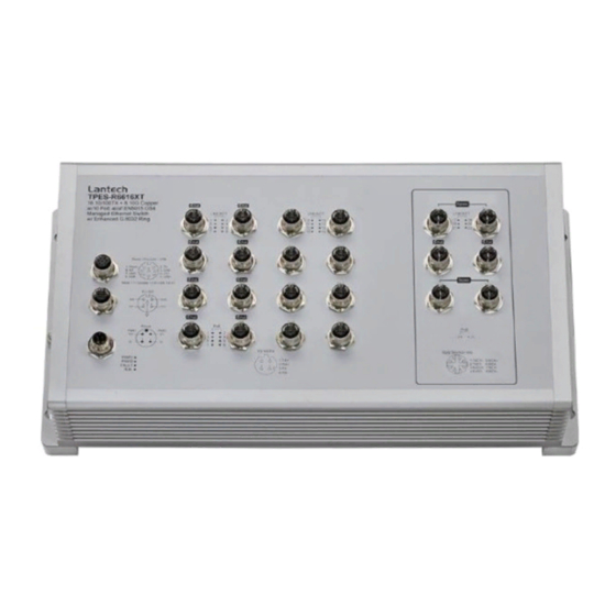
- Page 1 User Manual (Hardware) T(P)ES-R6616XFT 16 10/100TX + 4 10G Copper + 2 10G SR Fiber Q-ODC (w/ PoE at/af) EN50155 OS4 Managed Ethernet Switch T(P)ES-R6616XT 16 10/100TX + 6 10G Copper (w/ PoE at/af) EN50155 OS4 Managed Ethernet Switch Nov. 2019...
- Page 2 Recommendation for Shielded network cables STP cables have additional shielding material that is used to reduce external interference. The shield also reduces emissions at any point in the path of the cable. Our recommendation is to deploy an STP network cable in demanding electrical environments. Examples of demanding indoor environments are where the network cable is located in parallel with electrical mains supply cables or where large inductive loads such as motors or contactors are in close vicinity to the camera or its cable.
-
Page 3: Important Notice
Lantech Communications Global Inc. Products offered may contain software which is proprietary to Lantech Communications Global Inc. The offer or supply of these products and services does not include or infer any transfer of ownership. -
Page 4: Fcc Warning
FCC Warning This Equipment has been tested and found to comply with the limits for a Class-A digital device, pursuant to Part 15 of the FCC rules. These limits are designed to provide reasonable protection against harmful interference in a residential installation. This equipment generates, uses, and can radiate radio frequency energy. -
Page 5: Table Of Contents
Content Chapter 1 Hardware Description......5 Physical Dimension ........5 Package Content: ........6 IP Protection ..........7 LED Indicators..........10 Bypass design..........11 Charter 2. Hardware Installation ......13 Wall mount installation ......13 Chapter 3 Connect Cable ........16 Power input M12 connector......16 Console &... -
Page 6: Chapter 1 Hardware Description
Chapter 1 Hardware Description Lantech T(P)ES-R6616XFT / T(P)ES-R6616XT are high performance OS4 EN50155 10G uplink Ethernet switches with 16 10/100TX (with up to 16 PoE at/af injectors) by M12 connectors which provides L2 wire speed and advanced security function for connecting PD network. -
Page 7: Package Content
T(P)ES-R6616XT Aluminum case. IP-21, 390 (W) x 195 (D) x 105.3 (H) mm 1.2 Package Content: Product Console cable... -
Page 8: Ip Protection
1.3 IP Protection The IP Code, Ingress Protection Rating, sometimes also interpreted as International Protection Rating, classifies and rates the degree of protection provided against the intrusion (including body parts such as hands and fingers), dust, accidental contact, and water in mechanical casings and with electrical enclosures. It is published by the International Electrotechnical Commission (IEC) Solid particle protection The first digit indicates the level of protection that the enclosure provides against access... - Page 9 Liquid ingress protection The second digit indicates the level of protection that the enclosure provides against harmful ingress of water. Protected Level Testing for Details against — — protected Dripping Dripping water (vertically Test duration: 10 minutes water falling drops) shall have no Water equivalent to 1 mm harmful effect.
- Page 10 Powerful Water projected in powerful Test duration: at least water jets jets (12.5 mm nozzle) 3 minutes against the enclosure from Water volume: 100 litres per any direction shall have no minute harmful effects. Pressure: 100 kPa at distance of 3 m Immersion Ingress of water in harmful Test duration: 30 minutes...
-
Page 11: Led Indicators
1.4 LED Indicators The diagnostic LEDs that provide real-time information of system and optional status are located on the front panel of the industrial switch. The following table provides the description of the LED status and their meanings for the switch. Color Status Meaning... -
Page 12: Bypass Design
P21&P22 A network device is detected. (R6616XFT) Orange No device attached Link/Act Notification: P21&P22 ports are designed with 10G fiber interface and extend from CPU, not PHY chipset. So both these ports don’t support blinking status when data is forwarding via port21 or port22 or both. The port is operating in PoE mode. - Page 13 Bypass mechanism in close status...
-
Page 14: Charter 2. Hardware Installation
Charter 2. Hardware Installation There are no mechanically active moving parts in the switch, to fix the switch into an installation position, please use M4 size screw and corresponding nut and standard M4 screwdriver to install switch in the field. 2.1 Wall mount installation Please make sure the screw diameter is M4. - Page 15 Attach switch in wall with 4 screws Move down Tighten 4 screws...
-
Page 17: Chapter 3 Connect Cable
Chapter 3 Connect Cable After the hardware installation is complete, please connect the cable to the switch. All the external interfaces use M12 connector design and follow IEC 61076 standard except the for the fiber interface with QODC connector. The M12 connector on the 10G copper interface supports IEC 61076-2-109 standard, make sure the connector for the 10G cable also supports this standard or it will reduce the Max throughput of the 10G copper interface. - Page 18 Plug power connector and screw in clockwise direction to fix it.
-
Page 19: Console & Usb Dongle M12 Connector
3.2 Console & USB dongle M12 connector Ping assignment of console & USB dongle Note: The USB port is USB 2.0 speed, not USB 3.0 Make sure the connector is the right direction before you connect it. Plug console connector and screw in clockwise direction to fix it. -
Page 20: 10/100Tx Interface M12 Connector
3.3 10/100Tx interface M12 connector (Port 1 – Port 16 on TPES-R6616XFT and TPES-R6616XT) Ping assignment of the 10/100Tx port... - Page 21 Make sure the direction of connector is correct before you connect it. Plug the 10/100Tx connector and screw in clockwise direction to fix it.
-
Page 22: Interface M12 Connector
3.4 10G interface M12 connector (Port 17 – Port 20 on TPES-R6616XFT and Port 17 – Port 22 on TPES-R6616XT) Ping assignment of the 10G port Make sure the direction of connector is correct before you connect it. ... -
Page 23: Fiber Interface Q-Odc Connector
3.5 Fiber interface Q-ODC connector (Port 21 – Port 22 on TPES-R6616XFT & TES-R6616XFT) Make sure the direction of the connector is correct before you connect it. Plug 10G connector and move in different directions to make sure the Q-ODC connector... -
Page 24: Ground Interface M6 Connector
3.6 Ground interface M6 connector Ground The chassis is grounded via a separate grounding nut (M6). Use toothed locking washers for a good electrical connection. -
Page 25: Chapter 4 Maintenance
Ground screw of the switch Chapter 4 Maintenance Check each switch connection and make sure they are all screwed correctly. Keep the anti-dust cap on all un-used switch interface Access switch via web browser and check the below points: Compare the physical connection of the switch port with the switch icon on the web user interface to make sure the connecting status match each other. -
Page 26: Chapter 5 Console Management
Chapter 5 Console Management 5.1 Connecting to the Console Port The supplied cable has one M12 4-pole connector end and another RS-232 connector end. Attach the RS-232 connector end to a PC or terminal and the other M12 connector end to the console port of the switch. The connected terminal or PC must support the terminal emulation program. - Page 27 The settings of communication parameters Having finished setting up the parameters, click ‘OK’. When the blank screen shows up, press the Enter key to have the login prompt appear. Key in ‘admin’ (default value) for both User name and Password (use Enter key to switch), then press Enter and the Main Menu of console management should appear.
Need help?
Do you have a question about the TES-R6616XFT and is the answer not in the manual?
Questions and answers