
Related Manuals for Lantech TPGS-L5408MGTR


Summary of Contents for Lantech TPGS-L5408MGTR
- Page 1 TPGS-L5408MGTR 8 10/100/1000T + 4 1G/2.5G Copper w/8/10 PoE at/af EN50155 OS3 Managed Ethernet Switch User Manual (Hardware) Mar. 2020...
- Page 2 Recommendation for Shielded network cables STP cables have additional shielding material that is used to reduce external interference. The shield also reduces the emission at any point in the path of the cable. Our recommendation is to deploy an STP network cable in demanding electrical environments. Examples of demanding indoor environments are where the network cable is located in parallel with electrical mains supply cables or where large inductive loads such as motors or contactors are in close vicinity to the camera or its cable.
- Page 3 Lantech Communications Global Inc. Products offered may contain software which is proprietary to Lantech Communications Global Inc. The offer or supply of these products and services does not include or infer any transfer of ownership.
- Page 4 FCC Warning This Equipment has been tested and found to comply with the limits for a Class-A digital device, pursuant to Part 15 of the FCC rules. These limits are designed to provide reasonable protection against harmful interference in a residential installation. This equipment generates, uses, and can radiate radio frequency energy.
-
Page 5: Table Of Contents
Content Chapter 1 Introduction ........... 5 Chapter 2 Hardware Description......5 Physical Dimension ........5 IP Protection ..........6 LED Indicators ..........9 Bypass design ..........10 Chapter 3 Hardware Installation ......12 Rack Mounting ..........13 Power input M12 connector ......14 Console &... -
Page 6: Chapter 1 Introduction
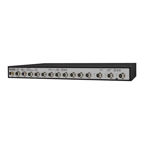
Chapter 1 Introduction Lantech TPGS-L5408MGTR is a high performance OS3 Ethernet switch with 8 10/100/1000T + 4 auto-sensing 1G/2.5G Copper w/8/10 (incl.8 copper + 2 uplink 2.5G copper) PoE 802.3af/at ports which provides advanced security function for network aggregation deployment. -
Page 7: Ip Protection
2.2 IP Protection The IP Code, Ingress Protection Rating, sometimes also interpreted as International Protection Rating, classifies and rates the degree of protection provided against the intrusion (including body parts such as hands and fingers), dust, accidental contact, and water in mechanical casings and with electrical enclosures. It is published by the International Electrotechnical Commission (IEC) Solid particle protection The first digit indicates the level of protection that the enclosure provides against access... - Page 8 Liquid ingress protection The second digit indicates the level of protection that the enclosure provides against harmful ingress of water. Protected Level Testing for Details against — — protected Dripping Dripping water (vertically Test duration: 10 minutes water falling drops) shall have no Water equivalent to 1 mm harmful effect.
- Page 9 water jets jets (12.5 mm nozzle) 3 minutes against the enclosure from Water volume: 100 litres per any direction shall have no minute harmful effects. Pressure: 100 kPa at distance of 3 m Immersion Ingress of water in harmful Test duration: 30 minutes up to 1 m quantity shall not be Immersion at depth of at...
-
Page 10: Led Indicators
2.3 LED Indicators The diagnostic LEDs that provide real-time information of system and optional status are located on the front panel of the industrial switch. The following table provides the description of the LED status and their meanings for the switch. Color Status Meaning... -
Page 11: Bypass Design
2.5G The port is operating in 2.5G mode. 2.4 Bypass design (Available on -BT/-BBT models) The bypass module is like an alarm relay but it has default position – close. When system finish booting procedures, CPU will ask bypass module change position from close to open and keep in open status. -
Page 13: Chapter 3 Hardware Installation
Chapter 3 Hardware Installation Hardware installation 1. Unpack the Industrial switch 2. Check if the Rack mount brackets are screwed on the Industrial switch or not. If the Rack mount brackets are not screwed on the Industrial switch, please refer to Rack Mounting section for rack installation. -
Page 14: Rack Mounting
3.1 Rack Mounting When installing the switch in a 19 inch rack, it must always be mounted horizontally with the top side up, This procedure requires the following items: ■ Eight bracket screws (included with the switch) ■ Two equipment rack brackets (included with the switch) ■... -
Page 15: Power Input M12 Connector
Power input M12 connector Spec. of power input Voltage of Power Input: Dual DC input, 16.8VDC~137.5VDC Total PoE budget: 80W Please make sure that the external power supply unit can satisfy the total power consumption in field. Ping assignment of power input ... -
Page 16: Console & Usb Dongle M12 Connector
Plug power connector and screw in clockwise direction to fix it. 3.2 Console & USB dongle M12 connector... - Page 17 Ping assignment of console & USB dongle Make sure the connector is the right direction before you connect it. Plug console connector and screw in clockwise direction to fix it.
-
Page 18: 10/100/1000T Interface M12 Connector
3.3 10/100/1000T interface M12 connector (Port 1 – Port 8) Ping assignment of the 10/100/1000T port Make sure the direction of connector is correct before you connect it. Plug 10/100/1000T connector and screw in clockwise direction to fix it. -
Page 19: Interface M12 Connector
3.4 1G/2.5G interface M12 connector (Port 9 – Port 12) Ping assignment of the 1G/2.5G port Make sure the direction of connector is correct before you connect it. - Page 20 Plug 10G connector and screw in clockwise direction to fix it.
-
Page 21: Di/Do M12 Connector
3.5 DI/DO M12 connector Ping assignment of DI/DO Make sure the connector is the right direction before you connect it. Plug DI/DO connector directly. -
Page 23: Chapter 4 Network Application
Chapter 4 Network Application ITU G.8032 Scheme Lantech G.8032 protocol is following ITU (International Telecommunication Unit) G.8032 v2 draft. The benefits of G.8032 are: 1. <50ms recovery time when failover 2. G.8032 has defined the protocol scheme, parameters, functions, test measures to be unified that the users can evaluate the possible network infrastructure without literally testing each brand in large scale. -
Page 24: Multiple Rings
Multiple Rings... -
Page 25: Dual Homing
Dual Homing... -
Page 26: Chain
Chain... -
Page 28: Chapter 5 Console Management
Chapter 5 Console Management 5.1 Connecting to the Console Port The supplied cable has one M12 4-pole connector end and another RS-232 connector end. Attach the RS-232 connector end to a PC or terminal and the other M12 connector end to the console port of the switch. The connected terminal or PC must support the terminal emulation program. - Page 29 The settings of communication parameters Having finished setting up the parameters, click ‘OK’. When the blank screen shows up, press the Enter key to have the login prompt appear. Key in ‘admin’ (default value) for both User name and Password (use Enter key to switch), then press Enter and the Main Menu of console management should appear.
Need help?
Do you have a question about the TPGS-L5408MGTR and is the answer not in the manual?
Questions and answers