Table of Contents
Advertisement
Quick Links
Advertisement
Table of Contents
Troubleshooting

Related Manuals for Supermicro SuperBlade SBI-621E-1NE34


Summary of Contents for Supermicro SuperBlade SBI-621E-1NE34
- Page 1 SuperBlade Server ® SBI-621E-1NE34 SBI-621E-1NE38 USER’S MANUAL Revision 1.0...
-
Page 2: About This Manual
For your system to work properly, please follow the links below to download all necessary of any such disputes. Supermicro's total liability for all claims will not exceed the price paid for the hardware product. drivers/utilities and the user’s manual for your server. -
Page 3: Table Of Contents
Contents Contents Contents 2.5 Replacing the Battery ......................41 2.6 Storage Drives ........................42 Chapter 1 Introduction Installing Drives .........................42 1.1 Overview ..........................8 Hot-Swap for NVMe Drives ....................46 Eligible Enclosures ......................8 2.7 System Cooling ........................47 1.2 System Features ........................9 Installing the Air Shrouds ....................47 Front View ...........................9 Checking the Server Air Flow ...................48 Drive Carrier Indicators ....................10... - Page 4 +1 (408) 503-8008 6.3 Troubleshooting Procedures .....................69 Email: marketing@supermicro.com (General Information) General Technique ......................69 Sales-USA@supermicro.com (Sales Inquiries) No Power ..........................69 Government_Sales-USA@supermicro.com (Gov. Sales Inquiries) No Video ...........................69 support@supermicro.com (Technical Support) System Boot Failure ......................70 RMA@supermicro.com (RMA Support) Memory Errors ........................70 Webmaster@supermicro.com (Webmaster) Losing the System Setup Configuration ................70...
-
Page 5: System Features
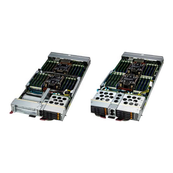
Chapter 1: Introduction Chapter 1: Introduction Chapter 1 1.2 System Features The following views of the system display the main features. Refer to Appendix C for additional specifications. Introduction Front View Liquid Cooling 1.1 Overview Ports Control Panel The SBI-621E-1NE34/38 blade is a compact self-contained server that connects into a pre- cabled enclosure that provides power, cooling, management and networking functions. -
Page 6: Drive Carrier Indicators
Chapter 1: Introduction Chapter 1: Introduction Drive Carrier Indicators Control Panel Each drive carrier has two LED indicators: an activity indicator and a status indicator. Drive Carrier LED Indicators Color Blinking Pattern Behavior for Device Green Blinking Activity Activity Green Solid On No activity Amber... -
Page 7: Top View
Chapter 1: Introduction Chapter 1: Introduction Top view Blade Components Item Feature Description SBI-621E-1NE34: four hot-swap E3.S (7.5 mm) drives Drives SBI-621E-1NE38: eight hot-swap E3.S (7.5 mm) drives Processors and heatsinks Mezzanine Connector DIMMs 32 memory slots, DDR5 Cover Partial chassis cover Mezzanine Network mezzanine add-on card Expansion Cards... -
Page 8: Motherboard Layout
P2-D1MMG2 P2-D1MMD1 JMEZZ1 Mezzanine card Slot1 (used for daughter card) P2-D1MMG1 P2-D1MMH2 Supermicro Advanced Input/Output Module (AIOM) sideband connector used JOCP_SB1 P2-D1MMH1 JAIOM_PWR2 to support PCIe 5.0 x8 MCIO Connectors 5/6 (JMCIO5/JMCIO6) JMCIO8 Supermicro Advanced Input/Output Module (AIOM) sideband connector used JOCP_SB2 to support PCIe 5.0 x8 MCIO Connectors 7/8 (JMCIO7/JMCIO8) -
Page 9: Motherboard Block Diagram
Chapter 1: Introduction Motherboard Block Diagram CPU1-B1 CPU1-A1 CPU1-A2 CPU1-C1 CPU1-D2 CPU1-C2 CPU2-C2 CPU2-C1 CPU2-D2 CPU2-D1 CPU2-A2 CPU2-A1 CPU2-B2 CPU2-B1 CPU 2 CPU 1 DDR5 DDR5 PECI: 30 PECI: 31 CPU1-F2 CPU2-G2 CPU2-G1 CPU1-E1 CPU1-H1 CPU1-H2 CPU1-G2 CPU2-H2 CPU2-H1 CPU2-E2 CPU2-E1 CPU2-F2 CPU2-F1... -
Page 10: Installation And Setup
Chapter 2: Installation and Setup Chapter 2 Installation and Setup This chapter provides instructions on installing and replacing main system components. To prevent compatibility issues, only use components that match the specifications or part numbers. Up to five or ten blade modules may be installed into a blade enclosure, depending upon your enclosure and blade. -
Page 11: Installing A Blade Unit Into The Enclosure
Chapter 2: Installation and Setup Chapter 2: Installation and Setup 2.1 Installing or Removing the Blade Unit 2.2 Powering Up or Down Each blade unit may be powered on and off independently from the rest of the blades in the Installing a Blade Unit into the Enclosure enclosure. -
Page 12: Processor And Heatsink
When handling the processor, avoid touching or placing direct pressure on the LGA lands (gold contacts). Improper installation or socket misalignment can cause serious damage to the processor or socket, which may require manufacturer repairs. • Refer to the Supermicro website for updates on processor support. Installation Procedure Overview SP XCC SP MCC/LCC After preparing the system, and following ESD precautions, there are four steps to installing the processor and heatsink onto the motherboard. - Page 13 Chapter 2: Installation and Setup Chapter 2: Installation and Setup Create the Processor Carrier Assembly 2. Turn the processor over (with the gold pins up). Locate the CPU keys on the processor and the four latches on the carrier. Assembling the Process Carrier Assembly 1.
- Page 14 Chapter 2: Installation and Setup Chapter 2: Installation and Setup 3. Locate the lever on the processor carrier and press it down (E1A and E1B only). 5. Once aligned, carefully insert the CPU into the carrier, making sure that the CPU is secured by latches 1, 2, 3, and 4.
- Page 15 Chapter 2: Installation and Setup Chapter 2: Installation and Setup Assemble the Processor Heatsink Module 4. Align "a" on the processor carrier assembly with the triangular cutout "A" on the heatsink along with "b", "c", "d" on the processor assembly with "B", "C", "D" on the heatsink. Thermal grease is pre-applied on a new heatsink.
- Page 16 Chapter 2: Installation and Setup Chapter 2: Installation and Setup Remove the Socket Cover Install the PHM Remove the plastic protective cover from the socket by gently squeezing the grip tabs and To install the PHM into the CPU socket, follow these steps. pulling the cover off.
- Page 17 Chapter 2: Installation and Setup Chapter 2: Installation and Setup 3. Check the rotating wires (1, 2, 3, 4) to make sure that they are in the unlatched position. 6. Press all four rotating wires outward and make sure that the heatsink is securely latched to the CPU socket.
-
Page 18: Removing The Phm
Chapter 2: Installation and Setup Chapter 2: Installation and Setup Removing the PHM 4. Gently lift the PHM upward to remove it from the CPU socket. To remove the processor heatsink module (PHM) from the motherboard, follow these steps. 1. Shut down the system and unplug the AC power cord from all power supplies. 2. - Page 19 Chapter 2: Installation and Setup Chapter 2: Installation and Setup Removing the Carrier Assembly from the Heatsink Removing the Processor from the Carrier Assembly To remove the processor carrier assembly from the PHM, follow these steps: To remove the processor from the processor carrier, follow these steps. 1.
-
Page 20: Memory Support
Chapter 2: Installation and Setup Chapter 2: Installation and Setup CPU1 PCIe5.0x16 JOCP_SB1 MAC CODE 2.4 Memory CPU2 Memory Support P2-D1MMA2 P2-D1MMA1 Up to 8 TB with 3DS RDIMM/LRDIMM DDR5 ECC memory. For validated memory, use our P2-D1MMB2 P2-D1MME2 P2-D1MMB1 Product Resources page. - Page 21 XCC, MCC, LCC CPUs Max Series CPUs Use the DIMM slots listed below for memory modules. This memory population table is based on guidelines provided by Intel to support Supermicro motherboards. Memory Population 32 DIMM Slots Memory Population, 32 DIMM Slots...
-
Page 22: Installing Memory
Chapter 2: Installation and Setup Chapter 2: Installation and Setup 2.5 Replacing the Battery Installing Memory ESD Precautions The motherboard uses non-volatile memory to retain system information when system power is removed. This memory is powered by a lithium battery residing on the motherboard. Electrostatic Discharge (ESD) can damage electronic com ponents including memory modules. -
Page 23: Storage Drives
These carriers also help promote proper airflow. Carriers without drives must remain in the 2. Use the drive carrier handle to pull the drive out of the chassis. chassis for proper airflow. Note: Enterprise level storage drives are recommended for use in Supermicro systems. For information on recommended drives, visit the Supermicro website. -
Page 24: Hot-Swap For Nvme Drives
Chapter 2: Installation and Setup 2.7 System Cooling Hot-Swap for NVMe Drives Supermicro servers support NVMe surprise hot-swap. For better data security, NVMe orderly hot-swap is recommended. NVMe drives can be ejected and replaced remotely using the Installing the Air Shrouds BMC Dashboard. -
Page 25: Checking The Server Air Flow
Chapter 2: Installation and Setup Checking the Server Air Flow • Make sure there are no objects to obstruct airflow in and out of the server. • Do not operate the server without drive carriers in the drive bays. • Use only recommended server parts. -
Page 26: Headers And Connectors
The JTPM1 header is used to connect a Trusted Platform Module (TPM)/Port 80, which is available from Supermicro. A TPM/Port 80 connector is a security device that supports encryption and authentication in storage drives. It allows the motherboard to deny access if the TPM associated with the storage drive is not installed in the system. -
Page 27: Jumpers
Chapter 3: Motherboard Connections Chapter 3: Motherboard Connections 3.2 Jumpers RAID Key Header Intel VROC RAID Key header is located at JRK1. It supports VMD used in creating optional Explanation of Jumpers advanced NVMe RAID configurations. To modify the operation of the motherboard, jumpers are used to choose between optional RAID Key Header settings. -
Page 28: Led Indicators
Chapter 3: Motherboard Connections ME Recovery JPME1 is used for ME Firmware Recovery mode, which will limit system resource for essential function use only without putting restrictions on power use. In the single operation mode, online upgrade will be available in Recovery mode. ME Recovery Jumper Settings Jumper Setting... -
Page 29: Chapter 4 Software
If you will be using RAID, you must configure RAID settings before installing the Windows OS and the RAID driver. Refer to the RAID Configuration User Guides posted on our website at www.supermicro.com/support/manuals. Installing the OS 1. Create a method to access the MS Windows installation ISO file. That can be a USB flash or media drive. -
Page 30: Driver Installation
Some of these must be installed, such as the chipset driver. After accessing the website, go into the CDR_Images (in the parent directory of the above link) and locate the ISO file for your motherboard. Download this file to to a USB flash drive or media drive. -
Page 31: Superdoctor ® 5
4.4 BMC ® The Supermicro SuperDoctor 5 is a program that functions in a command-line or web-based The motherboard provides remote access, monitoring and management through the interface for Windows and Linux operating systems. The program monitors such system health... -
Page 32: Chapter 5 Optional Components
TPM associated with the storage drive is not installed in the system. • To enable the mdadm command and support for RSTe, install the patch from Details and installation procedures are at: • Linux: https://downloadcenter.intel.com/download/28158/Intel-Virtual-RAID-on-CPU-In- http://www.supermicro.com/manuals/other/TPM.pdf. tel-VROC-and-Intel-Rapid-Storage-Technology-enterprise-Intel-RSTe-Driver-for-Linux- • Windows: https://downloadcenter.intel.com/download/28108/Intel-Virtual-RAID-on- CPU-Intel-VROC-and-Intel-Rapid-Storage-Technology-enterprise-Intel-RSTe-Driver-for- Windows- •... -
Page 33: Additional Information
Chapter 5: Optional Components Additional Information Configuring Intel VMD Additional information is available on the product page for the Supermicro add-on card and VMD must be enabled on PCIe ports which have NVMe drives attached to them in order for the linked manuals. - Page 34 Chapter 5: Optional Components Chapter 5: Optional Components Caution: VMD must only be enabled on NVMe port resources. If VMD is enabled on other PCIe ports, the functionality of those ports will be impacted. See the table below. 4. Select “Intel VMD for Volume Management Device on” on Socket 0 (CPU1) or Socket 2 (CPU2) to enable VMD for devices under the respective CPU.
-
Page 35: Creating Nvme Raid Configurations
Chapter 5: Optional Components Chapter 5: Optional Components Creating NVMe RAID Configurations 7. Choose whether to make the NVMe drives in this IOU Hot Plug Capable by selecting Enabled or Disabled. 1. Open Advanced > Intel(R) Virtual RAID on CPU > All Intel VMD Controllers > Create RAID Volume. -
Page 36: Status Indications
Chapter 5: Optional Components Status Indications An LED indicator on the drive carrier shows the RAID status of the drive. Drive Carrier Status LED Indicator Status State (red) Normal function Locating 4 Hz blinking Fault Solid ON Rebuilding 1 Hz Blinking IBPI SFF 8489 Defined Status LED States Hot-Swap Drives Intel VMD enables hot-plug and hot-unplug for NVMe SSDs, whether from Intel or other... -
Page 37: Chapter 6 Troubleshooting And Support
Chapter 6 Troubleshooting and Support 6.1 Information Resources Website A great deal of information is available on the Supermicro website, supermicro.com. Figure 6-1. Supermicro Website • Specifications for servers and other hardware are available by clicking the Products option. •... -
Page 38: Bmc Interface
Security Center for recent security notices B13DEE changing any non hot-swap hardware components. Supermicro Phone and Addresses R1.01 General Technique If you experience unstable operation or get no boot response, try: 1. With power off, remove all but one DIMM and other added components, such as add-on 6.2 BMC Interface... -
Page 39: System Boot Failure
Adequate power supply: Make sure that the power supply provides adequate power to the system. Make sure that all power connectors are connected. Refer to the Supermicro If the system does not display Power-On-Self-Test (POST) or does not respond after the website for the minimum power requirements. -
Page 40: Crash Dump Using The Bmc Dashboard
In the event of a processor internal error (IERR) that crashes your system, you may want to provide information to support staff. You can download a crash dump of status information the wrong BIOS can cause irreparable damage to the system. In no event shall Supermicro using the BMC Dashboard. The BMC manual is available at https://www.supermicro.com/... - Page 41 BIOS recovery, follow the procedures below. Note 1: If you cannot locate the "Super.ROM" file in your drive disk, visit our website at www.supermicro.com to download the BIOS package. Extract the BIOS binary image into a USB flash device and rename it "Super.ROM" for the BIOS recovery use.
- Page 42 Chapter 6: Troubleshooting and Support Chapter 6: Troubleshooting and Support Note: Do not interrupt this process until the BIOS flashing is complete. 7. Press <Del> continuously during system boot to enter the BIOS Setup utility. From the top of the tool bar, select Boot to enter the submenu. From the submenu list, select Boot 9.
-
Page 43: Cmos Clear
If you need replacement parts for your system, to ensure the highest level of professional consists of contact pads to prevent accidentally clearing the contents of CMOS. service and technical support, purchase exclusively from our Supermicro Authorized Distributors/System Integrators/Resellers. A list can be found at: https://www.supermicro.com. -
Page 44: Vendor Support Filing System
Website: www.supermicro.com 6.10 Feedback Europe Supermicro values your feedback as we strive to improve our customer experience in all facets Address: Super Micro Computer B.V. of our business. To provide feedback on our manuals, please email us at techwriterteam@ Het Sterrenbeeld 28, 5215 ML supermicro.com. -
Page 45: Appendix A Bios Post Codes
Appendix A: BIOS POST Codes Appendix A: BIOS POST Codes Appendix A BIOS POST Messages BIOS Message Description BIOS POST Codes Previous POST did not complete successfully. POST loads default values and offers to run Setup. If the failure was caused by incorrect values and Previous boot incomplete - they are not corrected, the next boot will likely fail. -
Page 46: Terminal Post Errors
Appendix A: BIOS POST Codes Appendix A: BIOS POST Codes One long and two short beeps – video configuration error BIOS POST Messages One repetitive long beep – no memory detected BIOS Message Description nnnn kB Extended RAM Where nnnn is the amount of RAM in kilobytes successfully tested. Terminal POST Errors Passed nnnn Cache SRAM Passed... - Page 47 Appendix A: BIOS POST Codes Appendix A: BIOS POST Codes Terminal POST Errors Terminal POST Errors Code Description Code Description 1-3-1-1 Test DRAM refresh Test keyboard 1-3-1-3 Test 8742 Keyboard Controller Set key click if enabled Auto size DRAM Enable USB devices Initialize POST Memory Manager 2-2-3-1 Test for unexpected interrupts Clear 512 kB base RAM...
- Page 48 Appendix A: BIOS POST Codes Appendix A: BIOS POST Codes Terminal POST Errors Terminal POST Errors Code Description Code Description Detect and install external parallel ports Clear Boot flag Initialize PC-compatible PnP ISA devices Check for errors Re-initialize onboard I/O ports. Inform RomPilot about the end of POST.
- Page 49 Appendix A: BIOS POST Codes Appendix A: BIOS POST Codes Terminal POST Errors Boot Block Flash ROM Terminal POST Errors Code Description Code Description Initialize digitizer and display message Initialize interrupt vectors Unknown interrupt Initialize Run Time Clock Initialize video Initialize System Management Manager Output one beep Clear Huge Segment...
-
Page 50: Appendix B Standardized Warning Statements For Ac Systems
Este símbolo de aviso indica peligro. Existe riesgo para su integridad física. Antes de Read this appendix in its entirety before installing or configuring components in the Supermicro manipular cualquier equipo, considere los riesgos de la corriente eléctrica y familiarícese chassis. - Page 51 Appendix A: Warning Statements Appendix A: Warning Statements . ٌ ا ك ً ف حالة و ٌ يك أى تتسبب ف اصابة جسذ ة ٌ هذا الزهز ع ٌ خطز !تحذ ز Warnung قبل أى تعول عىل أي هعذات،يك عىل علن بالوخاطز ال ا ٌجوة عي الذوائز Vor dem Anschließen des Systems an die Stromquelle die Installationsanweisungen lesen.
-
Page 52: Power Disconnection Warning
Appendix A: Warning Statements Appendix A: Warning Statements Power Disconnection Warning Warnung Dieses Produkt ist darauf angewiesen, dass im Gebäude ein Kurzschluss- bzw. Warning! The system must be disconnected from all sources of power and the power Überstromschutz installiert ist. Stellen Sie sicher, dass der Nennwert der Schutzvorrichtung cord removed from the power supply module(s) before accessing the chassis interior nicht mehr als: 250 V, 20 A beträgt. -
Page 53: Equipment Installation
Appendix A: Warning Statements Appendix A: Warning Statements אזהרה מפני ניתוק חשמלי !אזהרה Attention יש לנתק את המערכת מכל מקורות החשמל ויש להסיר את כבל החשמלי מהספק Seul le personnel autorisé et le personnel de maintenance qualifié doivent être autorisés à installer, remplacer ou entretenir cet équipement.. -
Page 54: Battery Handling
Appendix A: Warning Statements Appendix A: Warning Statements Warnung Battery Handling Diese Einheit ist zur Installation in Bereichen mit beschränktem Zutritt vorgesehen. Der Zutritt zu derartigen Bereichen ist nur mit einem Spezialwerkzeug, Schloss und Schlüssel oder einer CAUTION: There is risk of explosion if the battery is replaced by an incorrect type. sonstigen Sicherheitsvorkehrung möglich. -
Page 55: Redundant Power Supplies
Appendix A: Warning Statements Appendix A: Warning Statements .هناك خطر االنفجار إذا تم استبدال البطارية بنوع غري صحيح ¡Advertencia! اسحبذال البطارية Puede que esta unidad tenga más de una conexión para fuentes de alimentación. Para cortar por completo el suministro de energía, deben desconectarse todas las conexiones. فقط... -
Page 56: Backplane Voltage
Appendix A: Warning Statements Appendix A: Warning Statements Backplane Voltage هناك خطز مه التيار الكهزبايئ أوالطاقة املىجىدة عىل اللىحة عندما يكىن النظام يعمل كه حذ ر ا عند خدمة هذا الجهاس Warning! Hazardous voltage or energy is present on the backplane when the system is operating. -
Page 57: Product Disposal
Appendix A: Warning Statements Appendix A: Warning Statements תיאום חוקי החשמל הארצי Attention !אזהרה La mise au rebut ou le recyclage de ce produit sont généralement soumis à des lois et/ou .התקנת הציוד חייבת להיות תואמת לחוקי החשמל המקומיים והארציים directives de respect de l'environnement. - Page 58 제거할 때 팬은 여전히 회전하고 있을 수 있습니다. 팬 조림품 외관의 열려있는 부분들로부터 Feuer verursachen. Die Richtlinien untersagen das Nutzen von UL oder CAS zertifizierten 손가락 및 스크류드라이버, 다른 물체들이 가까이 하지 않도록 배치해 주십시오. Kabeln (mit UL/CSA gekennzeichnet), an Geräten oder Produkten die nicht mit Supermicro Waarschuwing gekennzeichnet sind.
- Page 59 .قيرح وأ لطع يف ببستي دق ىرخأ تالوحمو تالباك يأ مادختسا .ميلسلا سباقلاو لصوملا مجح لبق نم ةدمتعملا تالباكلا مادختسا تادعملاو ةيئابرهكلا ةزهجألل ةمالسلا نوناق رظحيUL وأCSA ( ةمالع لمحت يتلاوUL/CSA) لبق نم ةددحملاو ةينعملا تاجتنملا ريغ ىرخأ تادعم يأ عمSupermicro.
-
Page 60: Specifications And Compliance
Appendix C: System Specifications Appendix C: System Specifications Appendix C Regulatory Compliance FCC, ICES, CE, VCCI, RCM, UKCA, NRTL, CB Applied Directives, Standards Specifications and Compliance EMC/EMI: 2014/30/EU (EMC Directive) Electromagnetic Compatibility Regulations 2016 FCC Part 15 ICES-003 VCCI-CISPR 32 Processors AS/NZS CISPR 32 Dual 4th or 5th Gen Intel Xeon Scalable processors in Socket E (LGA4677) with three UPIs (16GT/s max.) and a TDP... -
Page 61: Appendix C: System Specifications
Appendix C: System Specifications General Data Center Environmental Specifications Particulate contamination specifications Air filtration: Data centers must be kept clean to Class 8 of ISO 14644-1 (ISO 2015). The air entering the data center should be filtered with a MERV 11 filter or better. The air within the data center should be continuously filtered with a MERV 8 filter or better.
Need help?
Do you have a question about the SuperBlade SBI-621E-1NE34 and is the answer not in the manual?
Questions and answers