Table of Contents
Advertisement
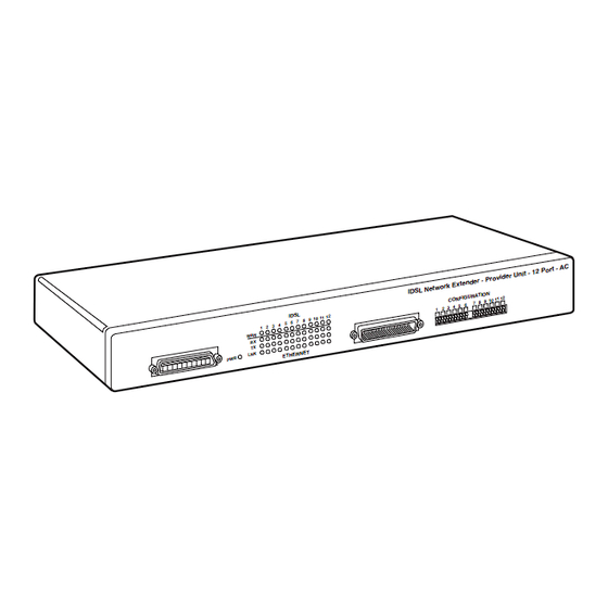
IDSL and SDSL Network Extenders
CUSTOMER
SUPPORT
INFORMATION
5 6 7
2 3 4
1
E T H E R
Order toll-free in the U.S. 24 hours, 7 A.M. Monday to midnight Friday: 877-877-BBOX
FREE technical support, 24 hours a day, 7 days a week: Call 724-746-5500 or fax 724-746-0746
Mail order: Black Box Corporation, 1000 Park Drive, Lawrence, PA 15055-1018
Web site: www.blackbox.com • E-mail: info@blackbox.com
LR0005A-KIT
LR0006A-AC
LR0006A-DC
LR0007A
ID S L
0 1 1 1 2
8 9 1
N E T
MARCH 2000
LR0010A-KIT
LR0011A-AC
LR0011A-DC
v id e r U
e r - P r o
E x t e n d
e t w o r k
ID S L N
N
U R A T IO
C O N F IG
2
1 0 1 1 1
7 8 9
4 5 6
1 2 3
LR0012A
C
P o r t - A
n it - 1 2
Advertisement
Table of Contents

Subscribe to Our Youtube Channel
Related Manuals for Black Box LR0005A-KIT


Summary of Contents for Black Box LR0005A-KIT
- Page 1 Order toll-free in the U.S. 24 hours, 7 A.M. Monday to midnight Friday: 877-877-BBOX SUPPORT FREE technical support, 24 hours a day, 7 days a week: Call 724-746-5500 or fax 724-746-0746 INFORMATION Mail order: Black Box Corporation, 1000 Park Drive, Lawrence, PA 15055-1018 Web site: www.blackbox.com • E-mail: info@blackbox.com...
- Page 3 FCC STATEMENT FEDERAL COMMUNICATIONS COMMISSION and INDUSTRY CANADA RADIO FREQUENCY INTERFERENCE STATEMENTS This equipment has been tested and found to comply with Class B Digital Device. the limits for a Class B computing device pursuant to Part 15 of the FCC Rules. These limits are designed to provide reasonable protection against harmful interference in a residential installation.
- Page 4 IDSL AND SDSL NETWORK EXTENDERS NORMAS OFICIALES MEXICANAS (NOM) ELECTRICAL SAFETY STATEMENT INSTRUCCIONES DE SEGURIDAD 1. Todas las instrucciones de seguridad y operación deberán ser leídas antes de que el aparato eléctrico sea operado. 2. Las instrucciones de seguridad y operación deberán ser guardadas para referencia futura.
- Page 5 NOM STATEMENT 12. Precaución debe ser tomada de tal manera que la tierra fisica y la polarización del equipo no sea eliminada. 13. Los cables de la fuente de poder deben ser guiados de tal manera que no sean pisados ni pellizcados por objetos colocados sobre o contra ellos, poniendo particular atención a los contactos y receptáculos donde salen del aparato.
- Page 6 IDSL AND SDSL NETWORK EXTENDERS TRADEMARKS USED IN THIS MANUAL Any trademarks mentioned in this manual are acknowledged to be the property of the trademark owners.
-
Page 7: Table Of Contents
2.3 Selecting IDSL Bandwidth ................8 2.4 Selecting SDSL Bandwidth ................9 2.5 LEDs ........................9 3. Installation ......................13 3.1 Installation for LR0005A-KIT, LR0007A, LR0010A-KIT, and LR0012A ..13 3.2 Installation for LR0006A-AC/DC and LR0011A-AC/DC ......14 Appendix. Port Pinouts ....................17 A.1 LR0005A-KIT, LR0007A, LR0010A-KIT, and LR0012A ......17... -
Page 8: Specifications
(5486 m) IDSL Interface — All: 2B1Q Encoding; LR0010A-KIT, LR0012A: RJ-45; LR0011A: RJ-21 50-pin telco Network Interface — All: IEEE 802.3 Ethernet 10BASE-T; LR0005A-KIT, LR0007A, LR0010A-KIT, LR0012A: RJ-45; LR0006A, LR0011A: (12) RJ-21 SDSL Interface — All: 2B1Q Encoding; LR0005A-KIT, LR0007A: RJ-45;... -
Page 9: Introduction
Ethernet frames are then passed across the SDSL or IDSL link. Each model’s function is described below. • The LR0005A-KIT includes one Provider unit and one Subscriber unit, to make one individual SDSL-to-Ethernet line. • The LR0006A-AC/DC is a 12-port Provider unit with 12 individual SDSL-to- Ethernet ports to which you can attach 12 Subscriber units. -
Page 10: Features
IDSL AND SDSL NETWORK EXTENDERS 2.2 Features • Traffic Indicators — All units feature an LED that will steadily pulse (once per second) when the SDSL or IDSL connection is operational and the unit is receiving valid data packets or status packets from the SDSL or IDSL Network Extender on the remote side of the link. -
Page 11: Selecting Sdsl Bandwidth
CHAPTER 2: Introduction 2.4 Selecting SDSL Bandwidth For LR0005A-KIT, LR0006A-AC/DC, and LR0007A, two switches are used to select the SDSL bandwidth for each SDSL/Ethernet port pairing. The table below shows switch configurations and associated bandwidth and distance support (in feet). - Page 12 IDSL AND SDSL NETWORK EXTENDERS LR0006A-AC/DC Power: Steady green indicates normal operation. WAN: Pulsing green (once per second) indicates that the SDSL connection is operational and the unit is receiving either valid data packets or status packets from the remote unit on the other side of the SDSL connection. Rx: Flashing amber indicates data received from Ethernet segment.
- Page 13 CHAPTER 2: Introduction LR0010A-KIT (P LR0012A) ROVIDER UBSCRIBER UNCTIONS AS IDSL LED: Pulsing green (once per second) indicates that the IDSL connection is operational and the unit is receiving either valid data packets or status packets from the remote unit on the other side of the IDSL connection. Power: Steady green indicates normal operation.
- Page 14 IDSL AND SDSL NETWORK EXTENDERS LR0012A IDSL LED: Steady pulsing green (once per second) indicates that the IDSL connection is operational and the unit is receiving either status packets from the IDSL Network Extender on the opposite side of the link or valid data packets across the link.
-
Page 15: Installation
Bandwidth 26 AWG 24 AWG Down Down 1.168 Mbps 9,000 12,000 Down 784 kbps 11,000 13,000 Down 528 kbps 13,000 15,000 272 kbps 15,000 17,000 The IDSL and SDSL Subscriber Units (LR0010A-KIT, LR0012A, LR0005A-KIT, LR0007A) do not use these switches. -
Page 16: Installation For Lr0006A-Ac/Dc And Lr0011A-Ac/Dc
IDSL AND SDSL NETWORK EXTENDERS NOTE The distance of the copper cable between the local Network Extender and the remote Network Extender will affect the linking of the DSL connection. If the distance is greater than a particular speed will support, the units will not link up. - Page 17 CHAPTER 3: Installation 2. For AC units, plug the power cord into both the power source and the back of the unit. (It doesn’t matter which order.) For DC units, attach the DC power leads and ground connection to the appropriate terminals indicated on the back of the unit and supply power to the unit.
- Page 18 IDSL AND SDSL NETWORK EXTENDERS 5. Verify the DSL connection via the DSL LED on the front of the unit. A steadily pulsing LED (once per second) indicates that the DSL connection is established and operational. 6. Connect the local RJ-21 Ethernet connector/cable to network equipment (such as an Ethernet switch) and verify physical link by the Lnk LED on the front of the unit.
-
Page 19: Appendix. Port Pinouts
APPENDIX: Port Pinouts Appendix: Port Pinouts A.1 LR0005A-KIT, LR0007A, LR0010A-KIT, and LR0012A Ethernet Pinout SDSL or IDSL Pinout Pin 1 Pin 1 Pin 2 Pin 2 Pin 3 Pin 3 Pin 4 Pin 4 Ring Pin 5 Pin 5 Pin 6... - Page 20 IDSL AND SDSL NETWORK EXTENDERS LR0006A-AC/DC (continued) Ethernet RJ-21 SDSL or IDSL RJ-21 Port Port RX5- Ring TX6+ TX6- Ring RX6+ RX6- Ring TX7+ TX7- RX7+ RX7- TX8+ TX8- RX8+ RX8- TX9+ TX9- RX9+ RX9- TX10+ TX10- RX10+ RX10- TX11+ TX11- RX11+ RX11-...
- Page 21 © Copyright 2000. Black Box Corporation. All rights reserved. 1000 Park Drive • Lawrence, PA 15055-1018 • 724-746-5500 • Fax 724-746-0746...
Need help?
Do you have a question about the LR0005A-KIT and is the answer not in the manual?
Questions and answers