Johnson Controls System 450 Series Installation Instructions Manual
Control modules with relay outputs
Hide thumbs
Also See for System 450 Series:
- Installation instructions and operators manual (54 pages) ,
- Technical bulletin (46 pages) ,
- Installation instructions manual (16 pages)
Advertisement
Quick Links
System 450™ Series Control Modules with Relay Outputs
Installation Instructions
C450CBN-1
C450CCN-1
Application
IMPORTANT: Use this System 450 Series Control
Module with Relay Output only as an operating
control. Where failure or malfunction of the System
450 control module could lead to personal injury or
property damage to the controlled equipment or
other property, additional precautions must be
designed into the control system. Incorporate and
maintain other devices, such as supervisory or
alarm systems or safety or limit controls, intended to
warn of or protect against failure or malfunction of
the System 450 control module.
System 450 is a family of modular, digital electronic
controls that is easily assembled and set up to provide
reliable temperature, pressure, and humidity control for
a wide variety of Heating, Air Conditioning, Ventilation,
and Refrigeration (HVACR) and commercial/industrial
process applications.
The System 450 control modules allow you to
configure custom application-specific control systems
with up to three input sensors and ten (relay and/or
analog) outputs, including control systems that can
monitor and control temperature, pressure, and
humidity applications simultaneously.
You can easily install and quickly configure a
stand-alone System 450 control module and sensor in
the field as a replacement control for almost any
temperature, pressure, and humidity control.
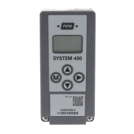
C450CxN-1 models are Single-Pole, Double-Throw
(SPDT) relay control modules with Liquid Crystal
Display (LCD) and four-button touch pad User Interface
(UI) that allows you to set up a System 450 control
system. C450CBN-1 models provide one SPDT relay,
C450CCN-1 models provide two SPDT relays.
Refer to the System 450 Series Technical Bulletin
(LIT-12011459) for more detailed information on
designing, installing, setting up, and troubleshooting
System 450 Series control systems. The System 450
technical bulletin can be accessed and downloaded on
the Johnson Controls® Online Product Literature Web
site at the following Web address:
http://cgproducts.johnsoncontrols.com/default.aspx
System 450™ Series Control Modules with Relay Outputs Installation Instructions
Part No. 24-7664-2675, Rev. G
Supersedes December 21, 2009
13
(1/2)
(7/16)
DIN Rail
127
(2-15/16)
Clips
(5)
61
(2-3/8)
1/2 in. Nominal
Trade Size
Conduit Hole
22
(7/8)
Figure 1: System 450 Module Dimensions, mm (in.)
Installation
Location Considerations
Observe the following System 450 location guidelines:
•
Ensure that the mounting surface can support the
module assembly, mounting hardware, and any
(user-supplied) panel or enclosure.
•
Mount the modules upright and plugged together in
a horizontal row where possible (Figure 3). DIN rail
mounting is highly recommended.
•
Mount modules on flat even surfaces.
•
Allow sufficient space for wires and connections.
•
Mount the modules in locations free of corrosive
vapors and observe the ambient operating
conditions in the Technical Specifications.
•
Do not mount the modules on surfaces that are
prone to vibration or in locations where radio
frequency or electromagnetic emissions may
cause interference.
•
Do not install the modules in airtight enclosures.
•
Do not install heat-generating devices in an
enclosure with the modules that may cause the
temperature to exceed the ambient operating limit.
Issued April 27, 2010
11
40
(1-9/16)
4
(3/16)
75
Screw
Slots
(Four)
61
(2-3/8)
1
Advertisement

Related Manuals for Johnson Controls System 450 Series


Summary of Contents for Johnson Controls System 450 Series
- Page 1 C450CCN-1 models provide two SPDT relays. • Do not mount the modules on surfaces that are Refer to the System 450 Series Technical Bulletin prone to vibration or in locations where radio (LIT-12011459) for more detailed information on frequency or electromagnetic emissions may designing, installing, setting up, and troubleshooting cause interference.
- Page 2 Mounting IMPORTANT: Use copper conductors only. Make Mount System 450 modules on 35 mm DIN rail all wiring in accordance with local, national, and (recommended) or directly to an even wall surface. To regional regulations. mount modules on DIN rail: IMPORTANT: Do not exceed the System 450 1.
- Page 3 0-10 VDC or 4-20 mA Sn-1 Sn-2 Analog Output Sn-3 Signal Active/Passive Sensor Jumpers L1 L2 Note: In 120 VAC applications, L1 must be the Hot lead and L2 must be the Neutral/Common lead. Figure 3: Example System 450 Heat/Cool System with Condenser Fan Speed Control Table 1: System 450 Terminal Wiring Information Label Terminal Function...
-
Page 4: Setup And Adjustments
Status or Setup Value: Displays the current Light-Emitting Diode (LED): Green LEDs input status, output status setup parameter on Relay Control Module and Relay value for the displayed input sensor, output Expansion Modules (only) indicates if the and/or setup parameter. Press select associated Relay Output is On or Off. - Page 5 Setting up a Control System in User Interface 4. Set up the control system outputs in the UI. See Setting up System 450 Outputs on page 8. System 450 control modules have a back-lit LCD and a four-button touch pad UI (Figure 4) that enable you to IMPORTANT: Do not change the module positions set up your control system.
- Page 6 150 to 750 P499Rxx-107C Refer to the System 450 Series Modular Controls Product Bulletin (LIT-12011458), Catalog Page (LIT-1900549), or Technical Bulletin (LIT-12011459) for complete ordering information for System 450 compatible sensors and transducers. System 450™ Series Control Modules with Relay Outputs Installation Instructions...
- Page 7 Table 4: System 450 Sensor Setup Information and Procedures LCD Screen Name, Description/Function, User Action, and Example Sensor Setup Start Screen: The Sensor Setup Start screen is the first screen displayed when you -- - access the System 450 setup screens. From the Sensor Setup Start screen you can navigate to the Output Setup Start screens or the Sensor Setup screens.
- Page 8 Setting up System 450 Outputs 3. For Relay Outputs, see Setting up a Relay Output (OUTRx) and Table 5 for setup information and After you build and connect power to your control procedures. system module assembly, the output numbers and output types for your control system are automatically For Analog Outputs, see Setting up an Analog assigned in the UI.
- Page 9 Table 5: System 450 Relay Output Setup Screen Information and Procedures (Continued) LCD Screen Name, Description/Function, User Action, and Example Minimum Relay ON Time Selection Screen: Minimum ON Time range is 0 to 300 seconds. 5. Press to select the minimum time that the output relay remains On after reaching the Relay ON value, then press to save your selection and go to the Minimum Relay OFF Time Selection Screen.
- Page 10 Figure 6 shows an example of the analog output setup Proportional Band values and the resulting output signal in a typical space 100% heating application (SP > EP and OSP < OEP). SP > EP °F SP = 70 ( ) Table 6 shows the four Control Ramp icons and the °F EP = 65 ( )
- Page 11 See Table 7 for setup information, procedures, and screen examples for analog outputs. Table 7: System 450 Analog Output Setup Screens Information (Part 1 of 2) LCD Screen Name, Description/Function, User Action, Example Analog Output Setup Start Screen: The output number and output type (relay or analog) are -- - automatically assigned when you connect power to your control system’s module assembly.
-
Page 12: Technical Specifications
Table 7: System 450 Analog Output Setup Screens Information (Part 2 of 2) LCD Screen Name, Description/Function, User Action, Example Sensor Failure Mode Selection Screen: 8. Press to select this output’s mode of operation if the sensor or sensor wiring fails. Press to save your selection and go to the Edit Sensor Selection screen. - Page 13 The performance specifications are nominal and conform to acceptable industry standards. For application at conditions beyond these specifications, consult Johnson Controls Application Engineering at (414) 524-5535. Johnson Controls, Inc. shall not be liable for damages resulting from misapplication or misuse of its products.
- Page 14 Figure 7: System 450 Status Screens, Setup Screens, and Menu Flow Example System 450™ Series Control Modules with Relay Outputs Installation Instructions...
- Page 15 System 450™ Series Control Modules with Relay Outputs Installation Instructions...
- Page 16 507 E. Michigan Street, Milwaukee, WI 53202 Johnson Controls/PENN® is a registered trademark of Johnson Controls, Inc. All other marks herein are the marks of their respective owners. © 2010 Johnson Controls, Inc. System 450™ Series Control Modules with Relay Outputs Installation Instructions Published in U.S.A.
Need help?
Do you have a question about the System 450 Series and is the answer not in the manual?
Questions and answers