Table of Contents
Advertisement
Quick Links
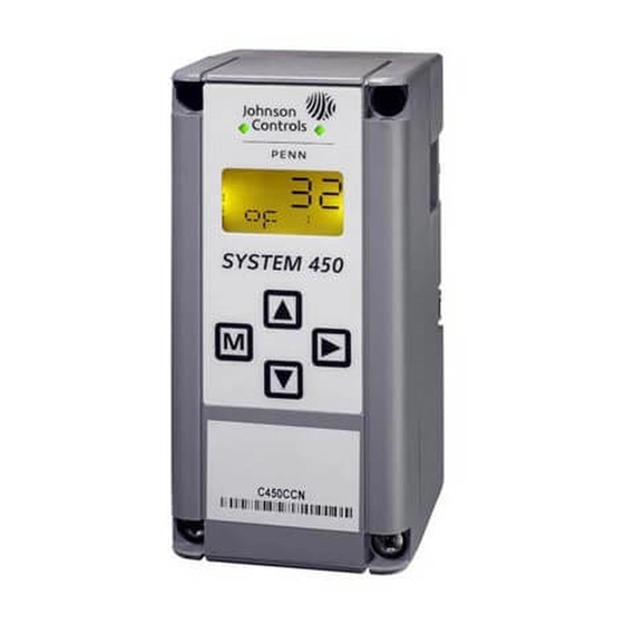
System 450™ Series Control Modules with Relay Outputs
Installation Instructions
C450CBN-2
C450CCN-2
Application
IMPORTANT: Use this System 450 Series Control
Module with Relay Output only as an operating
control. Where failure or malfunction of the System
450 control module could lead to personal injury or
property damage to the controlled equipment or
other property, additional precautions must be
designed into the control system. Incorporate and
maintain other devices, such as supervisory or
alarm systems or safety or limit controls, intended to
warn of or protect against failure or malfunction of
the System 450 control module.
System 450™ is a family of modular, digital electronic
controls that is easily assembled and set up to provide
reliable temperature, pressure, and humidity control for
a wide variety of Heating, Ventilating, Air Conditioning,
and Refrigeration (HVACR) and commercial/industrial
process applications.
The System 450 control modules allow you to
configure custom application-specific control systems
with up to three input sensors and ten (relay and/or
analog) outputs, including control systems that can
monitor and control temperature, pressure, and
humidity applications simultaneously.
You can easily install and quickly configure a
stand-alone System 450 control module and sensor in
the field as a replacement control for almost any
temperature, pressure, and humidity control.
C450CxN-2 models are Single-Pole, Double-Throw
(SPDT) relay control modules with Liquid Crystal
Display (LCD) and four-button touch pad User Interface
(UI) that allows you to set up a System 450 control
system. C450CBN-2 models provide one SPDT relay.
C450CCN-2 models provide two SPDT relays.
Refer to the System 450 Series Technical Bulletin
(LIT-12011459) for more detailed information on
designing, installing, setting up, and troubleshooting
System 450 Series control systems. The System 450
technical bulletin can be accessed and downloaded on
the Johnson Controls® Online Product Literature Web
site at the following Web address:
http://cgproducts.johnsoncontrols.com/default.aspx
System 450™ Series Control Modules with Relay Outputs Installation Instructions
Part No. 24-7664-2845, Rev. B
Supersedes December 15, 2011
Beginning with firmware Version 2.00, standard
System 450 control modules include the High
Input-Signal Selection and Differential Control features.
See High Input-Signal Selection on page 9 and
Differential Control on page 16 for more information.
Installation
13
(1/2)
(7/16)
DIN Rail
127
(2-15/16)
Clips
(5)
61
(2-3/8)
1/2 in. Nominal
Trade Size
Conduit Hole
22
(7/8)
Figure 1: System 450 Module
Dimensions, mm (in.)
Location Considerations
Observe the following System 450 location guidelines:
•
Ensure that the mounting surface can support the
module assembly, mounting hardware, and any
(user-supplied) panel or enclosure.
•
Mount the modules upright and plugged together in
a horizontal row where possible (Figure 3). DIN rail
mounting is highly recommended.
•
Mount modules on flat even surfaces.
•
Allow sufficient space for wires and connections.
•
Mount the modules in locations free of corrosive
vapors and observe the ambient operating
conditions listed in the Technical Specifications.
Issued January 23, 2012
11
40
(1-9/16)
4
(3/16)
75
Screw
Slots
(Four)
61
(2-3/8)
1
Advertisement
Table of Contents

Related Manuals for Johnson Controls C450CCN-2


Summary of Contents for Johnson Controls C450CCN-2
- Page 1 Mount the modules upright and plugged together in system. C450CBN-2 models provide one SPDT relay. a horizontal row where possible (Figure 3). DIN rail C450CCN-2 models provide two SPDT relays. mounting is highly recommended. Refer to the System 450 Series Technical Bulletin •...
- Page 2 • Do not mount the modules on surfaces that are Note: If you mount the modules on an uneven prone to vibration or in locations where radio surface, do not damage the housings when frequency or electromagnetic emissions may tightening mounting screws. Use shims/washers to cause interference.
- Page 3 Note: The relay output terminals connect to an internal SPDT Supply Power and relay and do supply any power to the application. Control Sensor Terminals Low Voltage (<30 V) Internal SPDT Relay Normally Closed/Off Position 6-Pin Module Connector Common (C) terminals are connected internally.
- Page 4 0-10 VDC or 4-20 mA Sn-1 Sn-2 Analog Output Sn-3 Signal Active/Passive Sensor Jumpers L1 L2 Note: In 120 VAC applications, L1 must be the Hot lead and L2 must be the Neutral/Common lead. Figure 3: Example System 450 Heat/Cool System with Condenser Fan Speed Control Status or Setup Value: Displays the current Light-Emitting Diode (LED): Green LEDs...
-
Page 5: Setup And Adjustments
Setup and Adjustments Sensor 1: Jumper positioned on one pin (or removed) sets Sn-1 to Active (Pressure). System 450 Component Requirements Sensor 2: Jumper positioned across two A System 450 control system consists of one control pins sets Sn-2 to Passive (Temperature). Sn-1 module, one to three control sensor inputs, and one to Sn-2... - Page 6 Screen example shows System 450 firmware version number 2.00 on the top of the screen. The number on xxxx the bottom of the screen (indicated in this example with xxxx) identifies the Johnson Controls firmware. Main (Input Status) Screens: During normal operation, the Main screens automatically scroll through the current status of each input sensor in your control system and display the sensor number, the unit of measurement, and the sensed condition value.
- Page 7 Accessing the System 450 Setup Start Screens 3. Press repeatedly to scroll through the Output Setup Start screens. See Figure 7. Access the System 450 Setup Start screens from the Main screen. See Table 2 for more information about Note: The UI returns to the Main screens after 2 the Setup Start screens.
- Page 8 Many of the 1,000 ohm Nickel temperature sensors that can be set up as HI°F or HI°C Sensor Types are not designed for use across the entire Range of Usable Values for HI°F and HI°C Sensor Types. Refer to the Technical Specifications sections in the TE-6000 Series Temperature Sensing Elements Product Bulletin (LIT-216288), the TE-6300 Series Temperature Sensors Product Bulletin (LIT-216320), and the TE-6800 Series Temperature Sensor Product Bulletin (LIT-12011542) to determine the temperature range that the various 1,000 ohm Nickel temperature sensors are specified to...
-
Page 9: High Input-Signal Selection
Table 4: System 450 Sensor Setup Screen Information and Procedures (Part 2 of 2) LCD Screen Name, Description/Function, User Action, and Example Sensor Setup Start Screen: When you have finished setting up all of the sensors for your control system, the display returns to the Sensor Setup Start screen. -- - Note: You can edit the sensor set up values at any time, if required. -
Page 10: Setting Up System 450 Outputs
Setting Up System 450 Outputs 4. To set up standard Relay Outputs and Relay Outputs with High Input-Signal Selection, see After you build and connect power to your control Setting Up a Relay Output for Standard Control or system module assembly, the output numbers and High Input-Signal Selection Control and Table 6 for output types for your control system are automatically setup information and procedures. - Page 11 Table 6: System 450 Setup Screen Information and Procedures for Relay Outputs with Standard Control and High Input-Signal Selection Control (Part 2 of 3) LCD Screen Name, Description/Function, User Action, and Example Relay ON Selection Screen: Select the value at which the relay turns On. Relay ON is defined as relay LED On/Lit, relay contacts N.O.
- Page 12 Table 6: System 450 Setup Screen Information and Procedures for Relay Outputs with Standard Control and High Input-Signal Selection Control (Part 3 of 3) LCD Screen Name, Description/Function, User Action, and Example Relay Output Setup Start Screen After you have set up this Relay Output, you can go to another Output Setup Start screen, the Sensor -- - Setup Start screen, or return to the Main screens.
- Page 13 Table 7 shows the four Control Ramp icons and the associated analog output setup value relationships. Table 7: Analog Output Control Ramp Icons Control Ramp Control Action Set the Analog Output Value Displayed on Relationships for the Desired Control Action and Corresponding Control Ramp SP <...
- Page 14 Table 8: System 450 Setup Screen Information and Procedures for Analog Output with Standard and High Input-Signal Selection Control (Part 1 of 2) LCD Screen Name, Description/Function, User Action, Example Analog Output Setup Start Screen: The output numbers and the output type (relay or analog) are determined by the module types and configuration of your control system’s module assembly and are -- - automatically assigned when you connect power to the module assembly.
- Page 15 Table 8: System 450 Setup Screen Information and Procedures for Analog Output with Standard and High Input-Signal Selection Control (Part 2 of 2) LCD Screen Name, Description/Function, User Action, Example Integration Constant Selection Screen: An integration constant allows you to set up proportional plus integral control for this analog output.
-
Page 16: Differential Control
Differential Control Differential Sensor Failure Mode Any output set up to reference the Differential Sensor Beginning with Version 2.00 firmware, standard System (Sn-d) enters the selected Sensor Failure mode when 450 control modules include Differential Control either Sn-1 sensor, Sn-2 sensor, or the sensor wiring capability. - Page 17 Table 10: System 450 Setup Screen Information and Procedures for Relay Outputs with Differential Control (Part 1 of 2) LCD Screen Name, Description/Function, Procedures, and Example Relay Output Setup Start Screen: The output numbers and the output type (relay or analog) are determined by the module types and configuration of your control system’s module assembly and are -- - automatically assigned when you connect power to the module assembly.
- Page 18 Table 10: System 450 Setup Screen Information and Procedures for Relay Outputs with Differential Control (Part 2 of 2) LCD Screen Name, Description/Function, Procedures, and Example Sensor Failure Mode Selection Screen: Select the differential output’s mode of operation if either of the referenced sensors (Sn-1 or Sn-2) or the sensor wiring fails.
- Page 19 Table 11: System 450 Setup Screen Information and Procedures for Analog Outputs with Differential Control (Part 2 of 3) LCD Screen Name, Description/Function, User Action, Example Differential Setpoint Selection Screen: Differential Setpoint (dSP) is the target value that the controlled system drives towards and along with Differential End Point (dEP), defines this output’s proportional band.
- Page 20 Table 11: System 450 Setup Screen Information and Procedures for Analog Outputs with Differential Control (Part 3 of 3) LCD Screen Name, Description/Function, User Action, Example Sensor Failure Mode Selection Screen: Select the differential output’s mode of operation if either of the referenced sensors (Sn-1 or Sn-2) or the sensor wiring fails.
- Page 21 Figure 7: System 450 Status Screens, Setup Screens, and Menu Flow Example System 450™ Series Control Modules with Relay Outputs Installation Instructions...
- Page 22 Figure 8: System 450 Status Screens, Setup Screens, and Menu Flow Example for Differential Control System 450™ Series Control Modules with Relay Outputs Installation Instructions...
-
Page 23: Technical Specifications
The performance specifications are nominal and conform to acceptable industry standards. For application at conditions beyond these specifications, consult Johnson Controls Application Engineering at (414) 524-5535. Johnson Controls, Inc. shall not be liable for damages resulting from misapplication or misuse of its products. - Page 24 507 E. Michigan Street, Milwaukee, WI 53202 Metasys® and Johnson Controls® are registered trademarks of Johnson Controls, Inc. All other marks herein are the marks of their respective owners. © 2012 Johnson Controls, Inc. System 450™ Series Control Modules with Relay Outputs Installation Instructions Published in U.S.A.
Need help?
Do you have a question about the C450CCN-2 and is the answer not in the manual?
Questions and answers