Advertisement
Quick Links
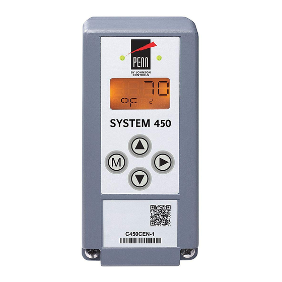
System 450™ Series Control Module with Ethernet
Communications
Installation Instructions
C450CEN-x
Application
IMPORTANT: Use this System 450™ Series
Control Module only as an operating control. Where
failure or malfunction of the System 450 control
module could lead to personal injury or property
damage to the controlled equipment or other
property, additional precautions must be designed
into the control system. Incorporate and maintain
other devices, such as supervisory or alarm systems
or safety or limit controls, intended to warn of or
protect against failure or malfunction of the
System 450 control module.
System 450™ is a family of modular, digital electronic
controls that is easily assembled and set up to provide
reliable temperature, pressure, and humidity control for
a wide variety of HVACR and commercial and industrial
process applications.
The System 450 control modules allow you to
configure custom application-specific control systems
with up to three input sensors and ten (relay or analog)
outputs, including control systems that can monitor and
control temperature, pressure, and humidity
applications simultaneously.
C450CEN-x control modules feature an LCD and
four-button touch pad UI that allows you to set up a
System 450 control system, and an RJ45 Ethernet
network port that enables you to connect your control
system to and communicate across an Ethernet
network.
The System 450 control module with Ethernet
communications has an integral web server that
supports browser access. The web server can be
configured to deliver System 450 web pages to client
browsers and allows you to monitor your control
system status and change your control system
configuration in simple, user-friendly web pages.
Refer to the
System 450™ Series Control Module with Ethernet Communications Installation
Part No. 24-7664-2934, Rev. C
Supersedes November 22, 2013
QuickLIT website
for the most up-to-date version of this document.
Refer to the System 450 Series Control Systems with
Network Communications Technical Bulletin
(LIT-12011826) for detailed information on designing,
installing, setting up, and troubleshooting System 450
Series control systems with network communications.
The technical bulletin can be accessed and
downloaded on the Johnson Controls® Online Product
Literature website at the following web address:
http://cgproducts.johnsoncontrols.com/default.aspx
System 450 control modules with network
communications also include the High Input-Signal
Selection, Differential Control, Output Signal Update
Rate, and Output Signal Dead Band features.
Installation
128
35 mm
(5)
DIN Rail
Mount
Channel
63
(2-1/2)
1/2 in. Conduit Hole
(Nominal Trade Size)
Figure 1: System 450 Module
Dimensions, mm (in.)
Issued December 6, 2013
13
(1/2)
75
(2-15/16)
40
40
(1-9/16)
(1-9/16)
38
(1-1/2)
63
(2-1/2)
63
(2-1/2)
Instructions
1
Advertisement

Related Manuals for Johnson Controls PENN System 450 Series


Summary of Contents for Johnson Controls PENN System 450 Series
- Page 1 The technical bulletin can be accessed and damage to the controlled equipment or other downloaded on the Johnson Controls® Online Product property, additional precautions must be designed Literature website at the following web address: into the control system.
- Page 2 Location Considerations 3. Clip the remaining modules to the right of the control module on to the DIN rail and plug the 6-pin Observe the following System 450 location guidelines: module connectors together (Figure 3). • Ensure that the mounting surface can support the Note: If your System 450 control system uses a module assembly, mounting hardware, and any power module, the power module must be plugged...
- Page 3 Wiring IMPORTANT: Electrostatic discharge can damage See Figure 2 and Table 1 for electrical termination System 450 modules. Use proper Electrostatic locations and wiring information. See Technical Discharge (ESD) precautions during installation and servicing to avoid damaging System 450 modules. Specifications on page 46 for electrical ratings.
- Page 4 System 450 Control Module with Ethernet Communications (C450CEN-1) 6-Pin System 450 Bus Connector Common terminals (C) are internally RJ45 connected. Ethernet Port Low-Voltage Input Sensors and Supply Power Terminals Figure 2: C450CEN-x Control Module with Ethernet Communications Showing Wiring Terminals Table 1: System 450 Control Module with Ethernet Communications Wiring Information Terminal Label...
- Page 5 C450CEN-x C450YNN-1 C450SBN-x C450SQN-x A99 Temperature Sensor Communications Power Expansion Module Expansion Module Sn-2 Control Sensor in UI Display Module OUTA2, OUTA3 Module OUTR1 F ° Sensor Type) P499 Pressure Transducer Sn-1 Control Sensor in UI Display RJ45 P500 Sensor Type) Ethernet Port Cooling Equipment...
- Page 6 Status or Setup Value: Displays the current LED: The green LEDs on the Comm input status, output status setup parameter Module indicate Ethernet communications value for the displayed input sensor, output performance on the Ethernet network. or setup parameter. Press select Blinking Right LED = proper receive activity a different parameter value when the value...
- Page 7 Main (Input Status) screen. The screen example shows System 450 firmware version number 2.00 on the top of the screen. The number on the bottom of the screen (indicated in this example with xxxx) identifies the Johnson Controls firmware.
- Page 8 Table 2: System 450 Startup Screen, Main Screens, Status Screens, and Setup Start Screens Information and Procedures (Part 2 of 2) LCD Screen Name, Description or Function, User Action, and Example Setup Start Screens: Setup Start screens are view-only screens, from which you can access the setup screens for the sensors or the displayed output;...
- Page 9 Table 3: System 450 Sensor Types, Setup Values, and Sensor or Transducer Product Codes (Part 2 of 2) Sensor Unit of Measurement Effective Range of Resolution Minimum Sensor Product Type Value Sensing Usable Increment Proportional Type Number (Condition/Units) Range Value or Control Values Band...
- Page 10 Table 4: System 450 Sensor Setup Screen Information and Procedures (Part 2 of 2) LCD Screen Name, Description or Function, User Action, and Example Sensor Type Selection Screens: The Sensor Type you select for an input sensor automatically determines the setup parameters and values for each output that is set up to reference that sensor. See Table 3 for information about System 450 sensors or transducers, Sensor Types, condition type, units of measurement, minimum control band or proportional band, setup values, value ranges, and product code numbers.
- Page 11 Use Table 5 to determine the negative PSI setup value High Input-Signal Selection that corresponds to your InHg target value. For System 450 control modules with communications example, if you want a relay output to go off when the include the High Input-Signal Selection control feature. sensed pressure reaches 7 InHg, you select the value The High Input-Signal Selection feature enables a -3.5 (psi) in the output’s Relay OFF Selection screen.
- Page 12 When an analog output is set up for differential control, Note: You must set up the input sensors for your System 450 controls the analog signal strength based control system before you can set up the outputs. See on the difference between Sn-1 and Sn-2 (Sn-d) Setting Up System 450 Sensors on page 8 for more relative to the user-selected differential setpoint (dSP) information.
- Page 13 Table 7: System 450 Setup Screen Information and Procedures for Relay Outputs (Part 2 of 4) LCD Screen Name, Description or Function, User Action, Example Sensor Selection Screen: The sensor you select here determines the output’s setup parameters and values, including condition type, unit of measurement, minimum control band, default setup values, and setup value ranges for several of the remaining output setup screens.
- Page 14 Table 7: System 450 Setup Screen Information and Procedures for Relay Outputs (Part 3 of 4) LCD Screen Name, Description or Function, User Action, Example When a relay output references Sn-1, Sn-2, Sn-3, HI-2, or HI-3, the Standard Relay OFF Selection screen appears.
- Page 15 Table 7: System 450 Setup Screen Information and Procedures for Relay Outputs (Part 4 of 4) LCD Screen Name, Description or Function, User Action, Example Minimum Relay ON Time Selection Screen: Select the minimum time that the output relay is required to stay on after it turns on.
- Page 16 The control action between the input signal and the Proportional output signal can be set up four ways, depending on Band the values selected for the Setpoint (SP), End Point 100% (EP), Percent Output Signal Strength at Setpoint SP > EP SP = 70 ( ) °F (OSP), and Percent Output Signal Strength at End...
- Page 17 Setting Up the Integration Constant, Update Rate, IMPORTANT: If you set the I-C, UP-R, or bNd and Output Deadband values to values other than the default value, you The System 450 Integration Constant (I-C), the Update should operate and observe the affected analog Output Signal Rate (UP-R), and the Output Signal outputs and process loops through the entire range Strength Deadband (bNd) are powerful tools for...
- Page 18 Table 9: System 450 Setup Screen Information and Procedures for Analog Output (Part 2 of 4) LCD Screen Name, Description or Function, User Action, Example When an analog output references Sn-1, Sn-2, Sn-3, HI-2, or HI-3, the Standard Setpoint Selection screen appears.
- Page 19 Table 9: System 450 Setup Screen Information and Procedures for Analog Output (Part 3 of 4) LCD Screen Name, Description or Function, User Action, Example Output Signal Strength at End Point Selection Screen: Select the strength of the signal that this output generates when the sensed condition is at the End Point value.
- Page 20 Table 9: System 450 Setup Screen Information and Procedures for Analog Output (Part 4 of 4) LCD Screen Name, Description or Function, User Action, Example Edit Sensor Selection Screen: This screen displays the sensor that this output currently references. Typically, no action is taken in this screen. But if you need to change the sensor that this output references, you can select a different sensor for this output in this screen.
- Page 21 Table 10: System 450 Ethernet Network Setup Screen Information and Procedures (Part 2 of 2) LCD Screen Name, Description or Function, User Action, and Example First IP-Address Octet Display Screen: Displays the first octet (one to three numerals) of the control module IP address.
- Page 22 The User password allows you to access the System In the User and Admin Password Setup screens, you Setup screens from the System Status screens must enter each digit in a screen individually and press (Figure 6). to save the single-digit value and go to the next digit in the four-digit password string.
- Page 23 Table 11: System 450 User Password Setup Screen Information and Procedures (Part 2 of 2) LCD Screen Name, Description or Function, User Action, and Example Change User Password Screen: Allows you to change the User password. Note: The factory-set default User Password is 0000. When the User password is set to 0000, the System 450 local (touchpad) password feature is disabled, and the password challenge screen does not appear when you access the System Setup screens.
- Page 24 Table 12: System 450 Administrator Password Setup Screen Information and Procedures (Part 2 of 2) LCD Screen Name, Description or Function, User Action, and Example Confirm New Admin Password Screen: Confirms the new Admin password entered in the previous (Change Admin Password) screen. The Confirm Admin Password screen is identified by a 2 in the superscript following AdMN.
- Page 25 Figure 6: System 450 Status Screens, Setup Screens, and Menu Flow Example System 450™ Series Control Module with Ethernet Communications Installation Instructions...
- Page 26 Setting Up Ethernet Communications Establishing a Direct Connection The Ethernet control module is shipped with the Direct Obtain the information in this section and record the Connect addressing mode enabled. When operating in values in the fields provided. Your network Direct Connect mode, the control module uses an administrator may be able to provide most, if not all, of integral DHCP server to provide an IP address to your...
- Page 27 4. Open the Windows® Internet Explorer® web 3. In the IP Address section on the Network browser on your computer. The Internet Explorer Configuration page, enter the assigned subnet browser at version 9 or later is recommended and mask in the Subnet Mask field. Use the value supported.
- Page 28 Note: You can monitor control system status and Note: You cannot make any changes to the system configure the control system parameters in both the configurations on the System Overview page. You must local UI (LCD and four-button touch pad) and the web log in to the web UI with the assigned user name and UI.
- Page 29 Table 13: System 450 Web UI Overview Page Descriptions, User Actions, and References (Part 1 of 2) Callout Identifier User Actions, Descriptions, References Number Item Name Name Enter the assigned System 450 web user name here. Login Field Note: You can assign a web user name in the Web User Name: field in the Web Server section on the Network Configuration page.
- Page 30 Table 13: System 450 Web UI Overview Page Descriptions, User Actions, and References (Part 2 of 2) Callout Identifier User Actions, Descriptions, References Number Item Name Analog Outputs Displays the setup values for each analog output in your control system, including the Status Section configured control ramp icon, analog output name (NAME), output signal status (STATUS), referenced sensor (SENS), setpoint (SP), end point (EP), output signal strength at setpoint...
- Page 31 System Configuration Page The System Configuration page provides system status information (just as the Overview page does) and Figure 9 shows an example System Configuration access to the Sensor Configuration page, Analog page for a System 450 control system that is already Output Configuration pages, Relay Output configured and in operation.
- Page 32 Table 14: System 450 Web UI System Configuration Page User Actions, Descriptions, and References (Part 2 of 2) Callout Identifier / Item User Actions, Descriptions, References Number Name Network Click Network to go to the Network Configuration page. Button Note: You set up your control system Network communications setting on the Network Configuration page.
- Page 33 Sensor Configuration Page This example uses a pressure sensor (Sn-1), a temperature sensor (Sn-2), and a humidity sensor Figure 10 shows an example Sensor Configuration (Sn-3). This control system example does not use the page for a System 450 control system that is already Differential Control feature.
- Page 34 Table 15: System 450 Web UI Sensor Configuration Page User Actions, Descriptions, and References (Part 2 of 3) Callout Identifier / Item User Actions, Descriptions, References Number Name Sensor Type Click the drop-down menu arrow to select the desired sensor type for Sn-1. The selected (Sn-1) sensor type provides the condition, the units of measurement, range of usable values, resolution increments, and minimum proportional or control band for each output that...
- Page 35 Table 15: System 450 Web UI Sensor Configuration Page User Actions, Descriptions, and References (Part 3 of 3) Callout Identifier / Item User Actions, Descriptions, References Number Name Sensor Name Assign a web UI sensor name for the Sn-3 sensor by entering a 16 character (maximum) (Sn-3) name in this field.
- Page 36 Analog Output Configuration Page Table 16 provides descriptions, user actions, and references for the items called out in Figure 11. Figure 11 shows an example Analog Output Configuration Page for a System 450 control system that is set up and operating. Figure 11: System 450 Analog Output Configuration Page Example Table 16: System 450 Web UI Analog Output Configuration Page, User Actions, Descriptions, and References (Part 1 of 3)
- Page 37 (1 to 6). The default value (0) indicates that no integration constant is applied to the analog output. Note: Johnson Controls recommends using the default value (0) when setting up your application for the first time. Refer to the System 450™ Series Modular Control Systems with Communications Control Modules Technical Bulletin (LIT-12011826) for information on setting up and testing an integration constant for your application.
- Page 38 Table 16: System 450 Web UI Analog Output Configuration Page, User Actions, Descriptions, and References (Part 3 of 3) Callout Identifier / Item User Actions, Descriptions, References Number Name Sensor Failure Select from the drop-down menu how you want the relay output to respond when the Mode of reference sensor or reference sensor wiring fails.
- Page 39 Relay Output Configuration Page Table 17 provides descriptions, user actions, and references for the items called out in Figure 12. Figure 12 shows an example Relay Output Configuration Page for a System 450 control system that is set up and operating. Figure 12: System 450 Relay Output Configuration Page Example Table 17: System 450 Web UI Relay Output Configuration Page, User Actions, Descriptions, and References (Part 1 of 3)
- Page 40 Table 17: System 450 Web UI Relay Output Configuration Page, User Actions, Descriptions, and References (Part 2 of 3) Callout Identifier / Item User Actions, Descriptions, References Number Name SENS (Reference Click the drop-down menu to select the sensor that this output references. The reference Sensor) sensor selected for this output is displayed in this field.
- Page 41 Table 17: System 450 Web UI Relay Output Configuration Page, User Actions, Descriptions, and References (Part 3 of 3) Callout Identifier / Item User Actions, Descriptions, References Number Name Click Ok to save any changes you made on this web page and go to the System Button Configuration page.
- Page 42 Table 18: System 450 Web UI Relay Output Configuration Page, User Actions, Descriptions, and References (Part 1 of 2) Callout Identifier / Item User Actions, Descriptions, References Number Name Logout and See System Configuration Page on page 31 for descriptions and user actions regarding the Configuration Logout, System, Sensor, and Network buttons.
- Page 43 Table 18: System 450 Web UI Relay Output Configuration Page, User Actions, Descriptions, and References (Part 2 of 2) Callout Identifier / Item User Actions, Descriptions, References Number Name Service Provider: Select the dynamic DNS provider. Options include None (dynamic DNS not used) or DynDNS.com.
- Page 44 Network Settings Reset Page When you change the IP Address mode, Static IP Address, Subnet Mask, Default Gateway, or HTTP Port value and click Ok, the communication controls module initiates a control reset and the Network Configuration Reset page (Figure 14) appears while the control resets the network settings for the new values.
- Page 45 Displays information about the control module model, firmware, and chip set. This Control Firmware information may be used for identification and advanced troubleshooting by Johnson Controls PENN product technical support.This information cannot be changed in Terminal Firmware the field. Control CPU Terminal CPU System 450™...
- Page 46 The performance specifications are nominal and conform to acceptable industry standards. For application at conditions beyond these specifications, consult Johnson Controls Application Engineering at (414) 524-5535. Johnson Controls, Inc. shall not be liable for damages resulting from misapplication or misuse of its products.
Need help?
Do you have a question about the PENN System 450 Series and is the answer not in the manual?
Questions and answers