Advertisement
P470 Electronic Pressure Control with Display
Product/Technical Bulletin
The P470 Electronic Pressure Control with Display is a
single-stage, On/Off, electronic pressure control with a
Single-Pole, Double-Throw (SPDT) output relay. The
control may be field set to operate in one of
three pressure ranges (0 to 100 psi, 0 to 500 psi, or
50 to 750 psi), as either an open-high or open-low
control.
The P470 control features a large LCD that displays
the sensed pressure and other system-status
indicators, as well as the adjustable setpoints in the
programming mode. The P470 control has a lockable,
three-button touchpad for adjusting setpoints, and a
front-panel LED that indicates the output relay status.
The P470 control uses a P499 Electronic Pressure
Transducer in conjunction with a WHA-PDK3 Wiring
Harness to sense system pressure. This arrangement
virtually eliminates the chance of a refrigerant leak
because there are no capillaries or bellows to break or
fail.
Table 1: Features and Benefits
Features
Easy to Read Liquid Crystal Display (LCD)
Three Field-Selectable Pressure Ranges
between 0–750 psi
24 VAC, and 120 or 208/240 VAC Models
Lockable, 3-Button, Front-Panel Touchpad
Built-in, Adjustable, Anti-Short Cycle
Time-Delay
Uses an Economical and Versatile Transducer
and Wiring Harness
Refer to the
QuickLIT Web site
Benefits
Clearly displays the sensed pressure (and other control information),
and in many situations pressure may be monitored without applying
gauges to the controlled equipment
Provides the flexibility to cover most HVACR pressure applications with
three field-selectable pressure ranges; 0–100 psi with 5 psi minimum
differential, and 0–500 psi or 50–750 psi with 20 psi minimum
differential
Increases application options, with two controls that cover most
common voltages
Deters tampering and over adjustment of control settings by
unauthorized personnel
Reduces compressor short cycling and nuisance lockouts, which can
extend compressor life
Eliminates many of the constraints of capillary control applications and
allows up to a 100 ft (30.5 m) cable between control and transducer
P470 Electronic Pressure Control with Display Product/Technical Bulletin
Part No. 24-7664-2004, Rev. A
Supersedes November 1, 2000
for the most up-to-date version of this document.
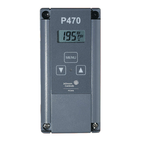
Figure 1: P470 Pressure Control with Transducer
and Wiring Harness (Control, transducer, and
harness must be purchased separately.)
Code No. LIT-125528
Issued January 26, 2012
1
Advertisement
Table of Contents

Related Manuals for Johnson Controls PENN P470


Summary of Contents for Johnson Controls PENN P470
- Page 1 P470 Electronic Pressure Control with Display Product/Technical Bulletin Code No. LIT-125528 Part No. 24-7664-2004, Rev. A Issued January 26, 2012 Supersedes November 1, 2000 Refer to the QuickLIT Web site for the most up-to-date version of this document. The P470 Electronic Pressure Control with Display is a single-stage, On/Off, electronic pressure control with a Single-Pole, Double-Throw (SPDT) output relay.
-
Page 2: Application Options
Application You may use a maximum of four P470 controls wired to a single P499 transducer. For example, high-pressure IMPORTANT: Use this P470 Electronic Pressure control and condenser fan cycling can use a common Control only as an operating control. Where failure transducer in conjunction with two P470 Controls to or malfunction of the P470 control could lead to control high-side pressure. -
Page 3: Liquid Crystal Display
Dimensions Figure 2: P470 Electronic Pressure Control Dimensions, inches (mm) Liquid Crystal Display The P470 control has an LCD that displays the sensed Indicates if the control is operating with either pressure during normal operation. See Figure 3. the Primary ( ) or Secondary ( ) setpoints. - Page 4 Cutout Pressure Range Jumper Cutout establishes the pressure value (in psi) at which Pressure Range Jumper positions establish the the output relay is de-energized, returning the contacts operational pressure range of the P470 control. Each to their normal positions, and the LED is off. of the three pressure ranges requires a specific P499 transducer with a matching range.
- Page 5 • Minimum required wire insulation rating is 90°C. • Recommended maximum wire length between the control and controlled equipment is 50 ft (15.2 m). • Recommended maximum cable length between the control and the transducer is 100 ft (30.5 m). The P470 control uses a P499 transducer to generate the 0.5–4.5 VDC input signal.
- Page 6 Set the jumpers as follows, using Figure 8 and Figure 9 as guides. 1. Disconnect all power sources to the P470 control. 2. Remove the control’s cover by loosening the four captive cover screws. 3. Position the jumpers to set the desired operating pressure range and lock or unlock the touchpad.
- Page 7 Table 2: Specified Transducer Models, Required Jumper Positions with the Resulting Operating Pressure Ranges, and Factory Settings at Startup Transducer Pressure Required Control’s Factory Factory Minimum Factory Set Model Connection P6 Jumper Operating Setpoint Setpoint Fitting Positions Pressure Differential Differential Number Cut-in Cutout...
-
Page 8: Equipment Needed
If the problem source and provide for proper power to the is with the control or transducer, contact a control. Johnson Controls/PENN sales representative for a replacement. Recheck for proper supply voltage. 2. Check for proper supply voltage to the pressure Determine what the proper supply voltage is for the transducer. - Page 9 b. The voltage must be 5.0 VDC (± 0.2 VDC). c. The transducer output signal voltage (V o ) If the voltage is in this range, proceed to increases proportionally with an increase in the Step 3. pressure at the transducer (psi ).
- Page 10 Note: When the LED is lit, the output relay should • The LED is On. Decrease cut-in setpoint be energized and the N.O. contacts should be below the displayed pressure by the minimum closed. differential pressure plus (for the selected operating pressure range) 10 psi.
- Page 11 Contact a 5 psi. The LED should go Off (and the N.O. Johnson Controls/PENN sales representative to contacts open). order a new control. See Ordering Information. Figure 15: LED Status for Open-low Controls...
- Page 12 Table 3: Display Codes and How to Respond to Them Flashing What the Display Codes Indicates, and How to Respond to Them Display Code Indicates the control’s operating pressure range has been changed, both P6 jumpers are in the Installed position, or a program failure has occurred.
-
Page 13: Ordering Information
See Table 2. in the order they are presented, to determine the problem. If the problem is with the control or transducer, contact a Johnson Controls/PENN sales representative for a replacement. Technical Specifications Table 5: Output Relay Contacts Electrical Ratings... - Page 14 The performance specifications are nominal and conform to acceptable industry standards. For application at conditions beyond these specifications, contact Refrigeration Application Engineering at (800) 275-5676. Johnson Controls, Inc. shall not be liable for damages resulting from misapplication or misuse of its products.
Need help?
Do you have a question about the PENN P470 and is the answer not in the manual?
Questions and answers