Johnson Controls System 450 Series Technical Bulletin
Condensing unit control system
Hide thumbs
Also See for System 450 Series:
- Installation instructions and operators manual (54 pages) ,
- Installation instructions manual (16 pages) ,
- Installation instructions manual (24 pages)

Related Manuals for Johnson Controls System 450 Series


Summary of Contents for Johnson Controls System 450 Series
- Page 1 System 450 Series C450CCU Condensing Unit Control System Technical Bulletin C450CCU Johnson Controls LIT-12013266 www.penncontrols.com 2020-10-21...
- Page 2 System 450 Series C450CCU Condensing Unit Control System Technical Bulletin...
-
Page 3: Table Of Contents
Application 1: Controlling the temperature of a walk-in freezer..........34 Application 2: Controlling the temperature of a walk-in cooler..........35 Application 3: Controlling the temperature of a walk-in cooler..........36 System 450 Series C450CCU Condensing Unit Control System Technical Bulletin... - Page 4 Application 4: Controlling the temperature of a walk-in freezer..........38 Troubleshooting condensing unit control systems................. 39 Ordering information..........................39 Related documentation..........................41 System 450 Series C450CCU Condensing Unit Control System technical specifications..... 42 Glossary of terms............................43 North American emissions compliance..................... 45 United States............................45 Canada..............................
-
Page 5: Introduction
You can add additional C450SCN relay output expansion modules for alarm functions. Important: Use the System 450 Series C450CCU condensing unit control module only as an operating control. To prevent personal injury or property damage to the controlled equipment, other property from failure or malfunction of the condensing unit control module, it is necessary to design additional precautions into the control system. -
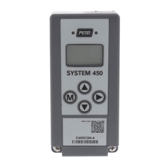
Page 6: Condensing Unit Control Module Ui
LCD. To navigate the control system status and setup screens and to set up the system parameters, use the four-button touchpad. Figure 1: Condensing unit control module UI System 450 Series C450CCU Condensing Unit Control System Technical Bulletin... - Page 7 • In Figure 1, the setup identifier or SP represents the setpoint. • Backlit LCD screen • During normal operation, the sensor status screens display on the LCD. System 450 Series C450CCU Condensing Unit Control System Technical Bulletin...
- Page 8 A relay output status displays as ON or OFF. For more information, see Setting up a condensing unit control system. System 450 Series C450CCU Condensing Unit Control System Technical Bulletin...
- Page 9 • Press and hold the Up and Down arrows simultaneously to access and exit the C450CCU’s menu. Press M to advance between the various start-up screens. • Screens with dashed outlines appear when certain configuration parameters or menu selections are met. System 450 Series C450CCU Condensing Unit Control System Technical Bulletin...
- Page 10 26: On this screen, you can view the error offset for sensor Sn-3. This screen is not available if the Sn-3 sensor type is set to ----. For • more information, see screen 25. Limits: +/- 10 psi or +/- 0.70 bar. System 450 Series C450CCU Condensing Unit Control System Technical Bulletin...
- Page 11 53: Use this screen to configure the action to take in the event of a suction pressure sensor failure on the input Sn-3. You can choose one of the following options: ON or OFF. The default setting for the compressor is ON. System 450 Series C450CCU Condensing Unit Control System Technical Bulletin...
-
Page 12: Module Assembly And Outputs
Note: Two A99BB-500C temperature sensors with 5m or 16-3/8 ft cable length are included with the C450CCU-4C controller. See Ordering information for available temperature sensors and pressure transducers. System 450 Series C450CCU Condensing Unit Control System Technical Bulletin... -
Page 13: System 450 Sensors And Sensor Types For C450Ccu
C450CCU condensing unit control systems use A99 Series positive temperature coefficient (PTC) sensors. Other temperature sensors cannot substitute the A99 Series sensors. For information about the available A99 Series temperature sensors, see Ordering information. System 450 Series C450CCU Condensing Unit Control System Technical Bulletin... -
Page 14: Defrost Termination Using A Binary Switch
Figure 1 shows a green LED on the control module housing that indicates the relay output status. The following example is for a relay output that is configured to energize the relay when the output status is ON. System 450 Series C450CCU Condensing Unit Control System Technical Bulletin... - Page 15 Factory default setting Desired fail-safe state Output relay contact NRGZ value for relay wired Refrigeration: N.C. Compressor or LLSV N.O. Single or high-speed N.C. evaporator fan N.O. Low-speed evaporator N.C. N.O. Defrost heater N.C. N.O. System 450 Series C450CCU Condensing Unit Control System Technical Bulletin...
-
Page 16: Relay Staging Delay
Select either ON, OFF or CYC for a Sn-1 sensor failure mode. For Sn-1, ON, OFF and CYC sensor failure modes are as follows: • Refrigeration ON • Refrigeration OFF System 450 Series C450CCU Condensing Unit Control System Technical Bulletin... -
Page 17: Condensing Unit Control System Example
Refrigeration or LLSV control circuit, OUTR1 (24 VAC to 240 VAC) High-speed evaporator fan control circuit: optional OUTR2 (24 VAC to 240 VAC) L1 and L2; 240 VAC supply power to power module System 450 Series C450CCU Condensing Unit Control System Technical Bulletin... -
Page 18: Assembling System 450 Modules
• Mount the modules in a location free of corrosive vapors and observe the ambient operating conditions listed in System 450 Series C450CCU Condensing Unit Control System technical specifications. • Allow sufficient space for connections, run wires, and to view the LCD. System 450 Series C450CCU Condensing Unit Control System Technical Bulletin... -
Page 19: Mounting Modules On Din Rail
Note: If you mount the modules on an uneven surface, use shims or washers to mount the module assembly evenly on the surface. Result Refer to the System 450 Series C450CCU Condensing Unit Control Module Installation Guide (24-7664-2888) for information about how to position and mount compatible sensors. - Page 20 Tout contact avec des composants conducteurs de tensions dangereuses risque d'entraîner une décharge électrique et de provoquer des blessures graves, voire mortelles. System 450 Series C450CCU Condensing Unit Control System Technical Bulletin...
- Page 21 Figure 5 shows the locations of and designations for the wiring terminals for System 450 standard control modules. Figure 5: Control and expansion modules with relay output System 450 Series C450CCU Condensing Unit Control System Technical Bulletin...
- Page 22 Connect to a P499 or P599 pressure transducer. Provides low-voltage common connections for passive or active sensors connected to Sn-1, Sn-2, or Sn-3. The common terminals are connected together internally. System 450 Series C450CCU Condensing Unit Control System Technical Bulletin...
- Page 23 Figure 6 shows the location of and designations for the wiring terminals on a C450YNN power module. provides descriptions, ratings, requirements, and recommended wire sizes for a C450YNN power module. Figure 6: C450YNN power module Table 8: C450YNN power module Callout Description High-voltage supply power terminals System 450 Series C450CCU Condensing Unit Control System Technical Bulletin...
-
Page 24: Setting Up A Condensing Unit Control System
The backlight low-level defines the backlight level when you do not use the UI. bKLH Backlight: high-level High The backlight high-level defines the backlight level when you access the UI and make adjustments to the user settings. System 450 Series C450CCU Condensing Unit Control System Technical Bulletin... - Page 25 1.0 bar • P15 Sensor: -1.0 to 15.0 • ON: Compressor ON Sensor 3 fail mode: Action to take in the event of a pressure sensor failure. • OFF: Compressor OFF System 450 Series C450CCU Condensing Unit Control System Technical Bulletin...
- Page 26 Schedule: Defrost 6 format, dF-7 --:-- or None Schedule: Defrost 7 based on CLK dF-8 --:-- or None Schedule: Defrost 8 setup. Unused slots show the following blinking sign: --:-- System 450 Series C450CCU Condensing Unit Control System Technical Bulletin...
-
Page 27: Determining Output Numbers And Output Types
• When the sensor status screens autoscroll, press and hold Up and Down simultaneously for 5 seconds to go to the system setup screens. System 450 Series C450CCU Condensing Unit Control System Technical Bulletin... -
Page 28: Accessing And Navigating The Ui
Navigate to the following system setup menu screens in the condensing unit control module UI: • SENS: Sensor setup start. Configure the sensor types and error offsets for the sensors that the system uses. System 450 Series C450CCU Condensing Unit Control System Technical Bulletin... -
Page 29: Setting Up The Sensor Setup Screens
If required, set up Sn-2 and Sn-3 for your application. When you set up your sensor types and temperature sensor offsets, press Next to save your selections and to return to the SENS setup start screen. System 450 Series C450CCU Condensing Unit Control System Technical Bulletin... -
Page 30: Setting Up The Mode Setup Screens
Before you begin: You can navigate to the following defrost setup screens in the condensing unit control UI: • dEFR: Defrost setup start • dUR: Defrost duration • TERM: Defrost termination termperature • dRIP: Defrost drip time • dELY: Evaporator fan delay System 450 Series C450CCU Condensing Unit Control System Technical Bulletin... -
Page 31: Setting Up The Off Mode Fan Setup Screens
To set up the sensors and transducers in your control system, you must select the correct sensor type in the condensing unit control module UI for each temperature sensor and pressure System 450 Series C450CCU Condensing Unit Control System Technical Bulletin... -
Page 32: Setting Up The Sensor Type And Offsets
If you allow the UI to remain dormant for 2 minutes and the main screen begins to autoscroll. You can also return to the main screen by pressing Up and Down simultaneously while in any setup start screen. System 450 Series C450CCU Condensing Unit Control System Technical Bulletin... -
Page 33: Supported Alarms
The alarm displays again if the termination sensor is at or above the defrost termination setting at the start of the next defrost cycle. System 450 Series C450CCU Condensing Unit Control System Technical Bulletin... -
Page 34: Typical C450Ccu Applications
Cool supply air out Defrost heater Compressor Sn1: Space temperature sensor Sn2: Defrost termination sensor Sn3: Suction pressure sensor System 450 C450CCU: R1 and R2 (high-speed) System 450 power module System 450 Series C450CCU Condensing Unit Control System Technical Bulletin... -
Page 35: Application 2: Controlling The Temperature Of A Walk-In Cooler
Low- voltage input terminal blocks C450CCU condensing unit control module C450YNN power module C450SBN relay expansion module with one relay output OUTR1, 24 VAC to 240 VAC: Controls refrigeration, either compressor or solenoid valve System 450 Series C450CCU Condensing Unit Control System Technical Bulletin... -
Page 36: Application 3: Controlling The Temperature Of A Walk-In Cooler
• Low or medium temperature with electric defrost • Space temperature sensor • Evaporator temperature sensor or switch for defrost termination • Optional System 450 power module • Single or optional two speed evaporator fan motor control System 450 Series C450CCU Condensing Unit Control System Technical Bulletin... - Page 37 120 VAC or 240 VAC supply power terminals: Provide 120 VAC or 240 VAC supply power to optional C450YNN power module. Optional: OUTR3, 24 VAC to 240 VAC: Low-speed evaporator fan control circuit. OUTR4 Defrost output System 450 Series C450CCU Condensing Unit Control System Technical Bulletin...
-
Page 38: Application 4: Controlling The Temperature Of A Walk-In Freezer
OUTR3: Output relay 3 terminal block. Connects to and controls the low-speed on a two-speed evaporator fan. You need a C450 expansion module to provide OUTR3. System 450 Series C450CCU Condensing Unit Control System Technical Bulletin... -
Page 39: Troubleshooting Condensing Unit Control Systems
Power module: Provides 24 V to System 450 module assembly: 120 VAC or 240 VAC supply power input terminals C450SBN-4C Relay expansion module with one SPDT relay output C450SCN-4C Relay expansion module with two SPDT relay outputs System 450 Series C450CCU Condensing Unit Control System Technical Bulletin... - Page 40 P499RCPS102K 0 psis to 200 psis, sealed for wet, freeze and thaw applications; WHA-PKD3-200C wire harness included. P499RCP-101C 0 psig to 100 psig; order a WHA-PKD3 type wire harness separately. System 450 Series C450CCU Condensing Unit Control System Technical Bulletin...
-
Page 41: Related Documentation
System 450 Series C450 CCU Condensing Unit 24-7664-03809 condensing unit control modules Control Module Installation Guide A99B Series Temperature Sensors Product/ Installing and wiring the A99 Series LIT-125186 temperature sensors Technical Bulletin 24-7664-1636 System 450 Series C450CCU Condensing Unit Control System Technical Bulletin... -
Page 42: System 450 Series C450Ccu Condensing Unit Control System Technical Specifications
System 450 Series C450CCU Condensing Unit Control System technical specifications Table 30: System 450 Series C450CCU Condensing Unit Control System technical specifications Specification Description Product System 450 Series C450CCU condensing unit control module Power supply Use one of the following power supplies: •... -
Page 43: Glossary Of Terms
Table 30: System 450 Series C450CCU Condensing Unit Control System technical specifications Specification Description Compliance United States: cULus Listed; UL 60730-1, File E27734; FCC Compliant to CFR47, Part 15, Subpart B, Class B Canada: cULus Listed; CAN/CSA-E60730-1, File E27734; Industry Canada (IC) Compliant to Canadian ICES-003, Class B limits Europe: CE Mark –... - Page 44 Sn-3 terminal and a Common (C) terminal on the low-voltage terminal block on the system’s control module. For more information, see Setting up the sensors and transducers. System 450 Series C450CCU Condensing Unit Control System Technical Bulletin...
-
Page 45: North American Emissions Compliance
Cet appareil numérique de la Classe (B) respecte toutes les exigences du Règlement sur le matériel brouilleur du Canada. Product warranty This product is covered by a limited warranty, details of which can be found at www.johnsoncontrols.com/buildingwarranty. System 450 Series C450CCU Condensing Unit Control System Technical Bulletin... -
Page 46: Single Point Of Contact
For more contact information, refer to www.johnsoncontrols.com/locations. Contact information Contact your local branch office: www.johnsoncontrols.com/locations Contact Johnson Controls: www.johnsoncontrols.com/contact-us © 2020 Johnson Controls. All rights reserved. All specifications and other information shown were current as of document revision and are subject to change without notice.
Need help?
Do you have a question about the System 450 Series and is the answer not in the manual?
Questions and answers