Table of Contents
Advertisement
Available languages
Available languages
TD2000
TD2000R
137
306
272
272
60
170
Posto esterno Antivandalo serie TD2000 per
sistema digitale DUO
Pulsantiera con 16 tasti, 4 simboli per lo stato del sistema ed LCD
alfanumerico, permette di comporre ed inviare chiamate sul bus
digitale DUO.
Dati tecnici
Alimentazione
Assorbimento a riposo
Assorbimento in funzionamento
Tempo azionamento serratura
Illuminazione minima
Led telecamera
Sensore
Ottica
Messa a fuoco
Morsetti
LP/LP
Bus DUO
PB/PB
Pulsante apertura serratura
Ingresso telecamera supplementare (PAL)
V/M
Serratura elettrica
S+/S-
Contatti relè ausiliario
C/NO/NC
Plaque de rue vidéophonique TD2000 pour le
système digital DUO
Plaque de rue à 16 boutons-poussoirs, 4 symboles pour l'état du
système et afficheur LCD alphanumérique, permet de composer
et d'adresser des appels sur bus digitale DUO.
Données techniques
Alimentation
Absorption à repos
Absorption en fonctionnement
Temps d'activation de la gâche
Eclairage minimum
Led caméra
Capteur
Objectif
Mise au point réglable
Bornes
LP/LP
Bus DUO
PB/PB
Bouton-poussoir ouvre porte
V/M
Entrée pour camera supplémentaire (PAL)
S+/S-
Gâche électrique
C/NO/NC
Contacts du relais auxiliaire
TD2000A
137
306
272
60
60
170
TD2000-TD2000R TD2000A-TD2000RA
dalla linea DUO
60mA
0,40A
max. 10sec.
1,0 Lux
3 (bianchi)
CMOS 1/3"
2,3mm
0,3m ÷ ∞
TD2000-TD2000R TD2000A-TD2000RA
de la ligne DUO
60mA
0,40A
max. 10sec.
0,5 Lux
3 (blancs)
CMOS 1/3"
2,3mm
0,3m ÷ ∞
TD2000RA
137
137
306
272
60
170
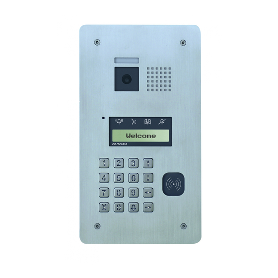
TD2000 Vandalproof Door Station for DUO
system
Door station with 16-button keypad, 4 icons for the system status
and alphanumeric LCD, allows to enter and send calls to the DUO
digital bus.
Technical data
Power supply
60mA
Stand-by current
Operating current
0,30A
Door lock activation time
----
Minimum illumination
LED's camera
----
----
Sensor
Lens
----
Focusing
----
Terminals
LP/LP
PB/PB
V/M
S+/S-
C/NO/NC
Placa de calle de videoportero TD2000 para
sistema digital DUO
Placa de calle con 16 teclas, 4 símbolos de estado del sistema
y LCD alfanumérico, permite marcar y enviar llamadas en el bus
digital DUO.
Datos técnicos
Alimentación
60mA
Consumo en reposo
0,30A
Consumo en funcionamiento
Tiempo actuación abrepuerta
----
Iluminación mínima
----
Led cámara
----
Sensor
----
Optica
----
Enfoque
Terminales
LP/LP
PB/GN
V/M
S+/S-
C/NO/NC
306
170
TD2000-TD2000R TD2000A-TD2000RA
from the DUO line
60mA
0.40A
1,0 Lux
3 (white)
CMOS 1/3"
2,3mm
0.3m ÷ ∞
DUO Bus
Door release push-button
Input for additional camera (PAL)
Electric door lock
Contacts of auxiliary relays
TD2000-TD2000R TD2000A-TD2000RA
de la línea DUO
60mA
0,40A
0,5 Lux
3 (blancos)
CMOS 1/3"
2,3mm
0,3m ÷ ∞
Bus DUO
Pulsador abrepuerta
Entrada para telecámara suplementaria (PAL)
Cerradura eléctrica
Contactos del relè auxiliar
Mi 2513/2
60mA
0,30A
max. 10sec.
----
----
----
----
----
60mA
0,30A
max. 10seg.
----
----
----
----
----
Mi 2513/2
- 1 -
Advertisement
Table of Contents

Related Manuals for Farfisa TD2000RA


Summary of Contents for Farfisa TD2000RA
- Page 1 LCD, allows to enter and send calls to the DUO digital bus. digitale DUO. Dati tecnici Technical data TD2000-TD2000R TD2000A-TD2000RA TD2000-TD2000R TD2000A-TD2000RA Power supply from the DUO line Alimentazione dalla linea DUO...
-
Page 2: Installazione
Installation Installazione Installation Installación A - Prima di murare la scatola d'in- casso, proteggere i fori di fissaggio della placca. B - Posizionare la pulsantiera in modo che i raggi solari o altre fonti luminose dirette o riflesse di forte intensità... - Page 3 Regolazioni Adjustments Régulations Regulaciónes Regolazione volumi Per regolare i volumi del microfono e dell'altoparlante, agire sui trimmer Regolazione dell’antilocale Regolazione innesco (effetto Larsen) Per eliminare un eventuale innesco (effetto Larsen), occorre pro- Anti-feedback (Larsen effect) adjustment cedere come segue: Réglage de l’effet Larsen Regulación del efecto Larsen - eseguire la chiamata dal posto esterno e sollevare il microtelefono Regulação do efeito Larsen...
- Page 4 Serratura elettrica Electric door lock La serratura elettrica è azionata direttamente dal posto esterno, As shown in the installation diagrams, the electric lock is operated ma affinché il sistema funzioni correttamente la serratura elettrica from the door station, but for a correct operation the electric lock deve essere del tipo 12Vca/1A max.
- Page 5 L'utilizzo del cavo art.2302, opportunamente studiato dalla ACI The cable art.2302 is the ideal solution for wiring DUO digital Farfisa, è raccomandato per la realizzazione di impianti digitali systems. The use of inappropriate cables may have an adverse DUO System. L'impiego di conduttori inadeguati potrebbe non effect on the performance of the system.
-
Page 6: Caratteristiche Funzionali
La pulsantiera antivandalo TD2000 è compatibile con i sistemi digitali Vandal proof push-button panel TD2000 is compatible with Farfisa DUO Farfisa e ne aumenta le potenzialità prevedendo la possibilità DUO digital systems and increases their capabilities allowing to di dividere l’impianto in 99 blocchi con 253 dispositivi ciascuno, nel divide the installation into 99 blocks, each of them with 253 de- sistema possono quindi essere installati più... -
Page 7: Caractéristiques Fonctionnelles
La plaque de rue anti-vandalisme TD2000 est compatible avec La placa de calle antivandálica TD2000 es compatible con los les systèmes numériques DUO Farfisa et augmente ses poten- sistemas digitales DUO Farfisa y aumenta sus potencialidades, tialités en prévoyant la possibilité de diviser l’installation en 99 porque prevé... -
Page 8: Menu' Di Programmazione
MENU' DI PROGRAMMAZIONE PROGRAMMAZIONI In modalità programmazione sulla prima riga del display compare Di seguito sono elencate le principali programmazioni di fabbrica; l'indicazione della programmazione che si sta eseguendo, mentre per variarle o per eseguirne altre, occorre procedere come indicato sulla seconda compaiono le funzioni che possono essere program- nei paragrafi seguenti. - Page 9 dedicato alla compatibilità con i dispositivi DUO tradizionali. - Ordina per password; visualizza la rubrica ordinata per pas- - di appartamento: in ciascun blocco gli utenti devono essere sword. Prima della password, tra i simboli < >, è riportato il individuati con un indirizzo univoco da 001 a 200;...
- Page 10 Elimina utente Format memory In questa sezione è possibile eliminare un utente dalla rubrica. Con questa funzione si azzera completamente la memoria del Con il tasto si entra in "Elimina utente" (se nella rubrica dispositivo, tutti i dati saranno cancellati. non è...
- Page 11 Indirizzo tasto PB (PB-PB) numero attualmente memorizzato (di fabbrica nessun numero). Il tasto PB (morsetti PB-PB) può essere usato per chiamare Con il tasto cancellare il numero, se presente, ed immet- direttamente un utente del sistema, invece di funzionare come tere il nuovo indirizzo, confermare con il tasto , si ritorna al "apriporta", in questo caso e necessario programmare l'indirizzo...
- Page 12 TLC AUX prioritaria Tasto per invio chiamata La telecamera prioritaria è la telecamera dalla quale il modulo Con questa funzione è possibile definire la modalità di invio della audio-video inizia la scansione ciclica delle telecamere ad esso chiamata che può essere scelta tra: associate.
- Page 13 Contrasto LCD Con questa funzione è possibile regolare il contrasto dell'LCD; Premendo il tasto si entra in modalità "Contrasto LCD" e sulla prima riga del display compare la scritta: - Contrasto LCD: con le frecce , è possibile aumen- tare o diminuire il contrasto così come indicato sul display. Ottenuto il livello desiderato premere per confermare, si ritorna al menù...
-
Page 14: Programming Menu
PROGRAMMING MENU PROGRAMMING The most important default settings are reported in the following; In programming mode, the first line of LCD shows the name of to change them or to store new parameters please proceed as the programming we are going to execute, while the second line indicated in the next paragraphs. - Page 15 fore the address, between symbols <>, is reported a number flat address and then press to move to the next program- representing the order with which the user has been stored; ming. users without password are listed for the last as “---”, but fol- - Enter Alias lowing their storing order (reported between <>).
- Page 16 System - Delete <n°> “user name”? With arrows select In this section, system parameters can be programmed, pressing <YES> or <NO> and then press ; choosing <NO> you key you access the parameter to be programmed, while will return to the selection of the user to be deleted, choosing pressing the key you return to the previous menu.
- Page 17 in this parameter sets the PB-PB button to send a call, Video OFF -2- Start (TD2000-TD2000R) consequently, if you wish to use PB-PB button to release In this parameter has to be stored the starting (lower) address the door lock, do not program any value in it. of the second group of users which do not have to receive the video signal (for example users with only audio intercom).
- Page 18 Timings By pressing the key you enter the programming mode " In this section it is possible to program the timings of all the key to send a call” and the first line of LCD shows: actuations of the system. By pressing you enter the pro- key to send call? With arrows select <YES>...
- Page 19 Default Selecting this command all the system parameters will be restored to their factory values with the exception of the user directory which remains programmed at it is. Attention: administrator password will be restored to its fac- tory value (0039). Pressing you enter the "Default"...
-
Page 20: Menu De Programmation
MENU DE PROGRAMMATION PROGRAMMATION En modalité programmation sur la première ligne de l’afficheur Ci-après sont répertoriées les principales programmations d’usine; apparait l’indication de la programmation en cours d’exécution, pour les modifier ou en effectuer d’autres, il faut procéder comme tandis que sur la seconde apparaissent les fonctions qui peuvent indiqué... - Page 21 est reporté le numéro d’ordre avec lequel l’utilisateur a été teur, de 01 à 99; taper l’adresse de bloc puis appuyer mémorisé. Appuyer pour passer à la liste ordonnée par pour passer à la programmation successive; le bloc 00 est nom.
- Page 22 <OUI > ou <NON> et ensuite appuyer pour passer à la au menu "Tout récupérer". Appuyer pour retourner en programmation successive. arrière dans le menu. - Active Relais: Activation relais auxiliaire; sélectionner avec les flèches ou la rubrique <OUI > ou <NON> et ensuite Attention: la fonction peut être exécutée à...
- Page 23 Pour la programmation de l’adresse sélectionne le menu Avec les flèches on sélectionne la fonction à pro- "Adresse relais" et appuyer la touche , sur l’afficheur ap- grammer, tandis qu’avec la touche on confirme la sélection. parait l’inscription "Entrer adresse de bloc" et à la fin de la se- A l’aide de la touche on retourne au menu précédent.
- Page 24 Vidéo OFF -2- End (TD2000-TD2000R) la première ligne de l’afficheur apparait l’inscription "Entrer Dans cette section on peut programmer l’adresse finale du se- temps" tandis qu’à la fin de la seconde ligne apparait le nu- cond groupe d’utilisateurs qui ne doivent pas recevoir le signal méro actuellement mémorisé...
- Page 25 Caméra (TLC) externe En activant cette fonction le poste externe gère une caméra externe outre celle à bord du dispositif. Quand du vidéophone arrivent les commandes "auto-allumage" le poste externe com- mute cycliquement entre les deux caméras et sur l’écran du vi- déophone les images relatives s’alternent.
-
Page 26: Menú De Programación
MENÚ DE PROGRAMACIÓN PROGRAMACIONES En modalidad “programación”, en la primera línea del display A continuación se listan las principales programaciones de fábri- aparece la indicación de la programación que se está ejecutan- ca. Para modificarlas o ejecutar otras, es preciso proceder según do, mientras que en la segunda aparecen las funciones que pue- se indica en los siguientes apartados. - Page 27 00 está destinado a la compatibilidad con los dispositivos do. Los usuarios sin alias se muestran en último lugar con DUO tradicionales. el símbolo “---” y ordenados por el número de orden con el - de apartamento: En cada bloque, los usuarios deben iden- cual han sido memorizados (aparece entre los símbolos <>).
- Page 28 Todos los parámetros del usuario han sido modificados. En el Download display, aparece durante un instante la leyenda “guardado” Si se presiona la tecla , el dispositivo se prepara para recibir y, luego, nuevamente el nombre del usuario que se acaba de un archivo de configuración mediante el puerto USB.
- Page 29 segunda línea, aparece el número actualmente memorizado Atención: Para identificar a los usuarios con direccio- (de fábrica 231). Con la tecla borrar el número, ingresar nes superiores a la memorizada, también es necesario tener la nueva dirección de la placa de calle (de 231 a 240) y con- en cuenta la dirección de bloque (por ejemplo, el usuario 03- firmar con la tecla , se vuelve al menú...
- Page 30 Cámara AUX 1÷8 cha, aparece la password actualmente programada (de fábrica Las placas de calleTD2000 pueden gestionar moduladores ví- 0039), borrarla con la tecla e ingresar la nueva password. deo exteriores (tipo VM2521), a los cuales pueden conectarse Presionar para confirmar. En el display, aparece la leyenda “guardado”...
- Page 31 Mensaje de Bienvenida Durante el funcionamiento normal, en el display de la placa de calle aparece un mensaje con las indicaciones fundamentales para realizar una llamada. El mensaje está formado por dos partes (2 líneas para 20 caracteres cada una) que se alternan cada 6 segundos.
-
Page 32: Collegamento Usb
PC the program "Contact Manager", last version can be down- installare sul PC il programma "Contact Manager" la cui versione loaded from the download area of the web site of ACI FARFISA aggiornata può essere scaricata nella sezione "download" del sito (www.acifarfisa.it). -
Page 33: Raccordement Usb
“Contact Manager”, cuya versión actualizada pue- Manager", la dernière version peut être téléchargée dans la sec- de descargarse en la sección “Download” del sitio web de ACI tion "téléchargement" du site ACI FARFISA (www.acifarfisa.it). FARFISA (www.acifarfisa.it). Pour le transfert des données opérer comme suit :... - Page 34 Note: Mi 2513/2 - 34 -...
- Page 35 Note: Mi 2513/2 - 35 -...
- Page 36 FUNCIONAMIENTO FONCTIONNEMENT Controlar que las conexiones del sistema estén efectuadas co- Contrôler que les raccordements de l’installation soient effectués rrectamente. Poner en funcionamiento el sistema, conectando el correctement. Mettre en fonction l’installation en raccordant alimentador a la red. En el display, aparece durante 3 segundos l’alimentateur au réseau;...
-
Page 37: Funzionamento
FUNZIONAMENTO OPERATIONS Controllare che i collegamenti dell'impianto siano effettuati cor- Check first that connections of the system have been done cor- rettamente. Mettere in funzione l'impianto collegando a rete l'a- rectly. Power ON the system, display will show for 3 seconds the limentatore;... - Page 38 Note: Mi 2513/2 - 38 -...
- Page 39 Note: Mi 2513/2 - 39 -...
- Page 40 Mi 2513/2 - 40 -...
Need help?
Do you have a question about the TD2000RA and is the answer not in the manual?
Questions and answers