
Related Manuals for Farfisa ST 720


Summary of Contents for Farfisa ST 720
- Page 2 In order to make the systems work properly it is necessary to install only foam, etc.) must be kept out of the reach of children. Farfisa equipment, keeping strictly to the items referred to in each diagram. The manufacturer cannot be held responsible for possible damages caused by improper, erroneous and unreasonable use.
- Page 3 TECHNICAL MANUAL 2006 edition INDEX Page General characteristics Composition of Studio series internal stations Intercoms - Internal stations - External door stations - Power supplies and service modules - Installation instructions - Installation diagrams Video Intercoms - Internal stations - External door stations - Power supplies, control units and service modules - Installation instructions - Installation diagrams...
- Page 4 GENERAL CHARACTERISTICS The Farfisa electronic call system allows for the For the realisation of basic video intercom Choosing the correct article realisation of intercom, video intercom, digital systems you need 7 common wires + 1 single When choosing the article and type of instal- for each user + common coaxial cable or twisted and intercom-telephone systems.
- Page 5 INTERNAL STATIONS COMPOSITION (MT11 - Gb2006)
- Page 6 The following pages show the installation diagrams that are most commonly used in intercom, video intercom and telephone systems. Upon request ACI Farfisa can supply installation diagrams for configurations that are not included in this manual. Systems with 1 or more main entrances...
- Page 7 INTERCOMS Technical manual 11 Edition 2006 Page INDEX Internal stations - Studio series intercoms - Compact series intercoms - Project series intercoms External door stations - Mody series push-button panels - Matrix series push-button panels - Profilo series push-button panels - ErreP/R series push-button panels - UP series push-button panels Power supplies...
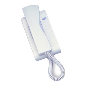
- Page 8 INTERNAL STATIONS INTERCOMS General characteristics of intercoms for systems with elec- tronic call Electronic call systems Accessories can use all intercoms of the Compact, Studio, ST 701. Single button unit for Project, PuntoVirgola ST720 intercoms. Maximum con- and 900 series (except tact current is 0.1A.
- Page 9 INTERNAL STATIONS INTERCOMS Studio series ST 703. Ringing volume adjustment ST 715. Switch module. It allows to acti- ST 716. Switch module with LED. It allows switch. vate or deactivate one of the intercom functions to activate/deactivate/divert one of the inter- (for example call, door lock release, etc.).
- Page 10 All modules described above can be installed multi-way intercom system it allows only the cable with 20 wires. inside the ST 720 intercoms. It must be kept in called user to be put in communication with the mind that they cannot be installed all at the external door station.
- Page 11 INTERNAL STATIONS INTERCOMS Compact series INTERCOMS Project series 77.5 " " " " " " " PT510EW. White electronic intercom with 1 KM810W. White electronic intercom with 1 button, spiral cord, electronic microphone, and button, spiral cord, electronic microphone, and possibility of installation of SR41 and SM50E possibility of installation of SR41, SM50E modules.
- Page 12 INTERNAL STATIONS INTERCOMS Project series Note It is recommended to install the PT502 LED module and the PT515 switch module in the " " last 2 positions marked with and To install them, the plastic button slides must be removed from the internal part of the intercom cover (see figure).
- Page 13 EXTERNAL DOOR STATIONS PUSH-BUTTONS MODY series Push-button panels in extruded aluminium made up Module frames complete with back box " " of modular elements. Suitable for the most diverse installation requirements. MD71. 72. 73. 74. Plastic back boxes complete with "...
- Page 14 EXTERNAL DOOR STATIONS PUSH-BUTTONS MODY series 1 row push-button modules ELECTRIC DOOR SPEAKER 25.5 Modules for electric door speaker (amplifier) " " " MD 10 MD 11 MD 12 without call buttons 1 call button 2 call buttons MD 30. It consists of a double amplifier (receiver and Button modules transmitter) with adjustable volume of 2 chan-...
- Page 15 EXTERNAL DOOR STATIONS PUSH-BUTTONS MODY series AMPLIFIED DOOR STATIONS ACCESS CONTROL KEYPAD PROXIMITY READER FOR ACCESS CONTROL " " " " " " " " " " " " MD 100. 1 button module. FC52P. FP52. Fittable in all intercom, telephone, intercommu- Access control keypad with 12 digits and 2 This article allows for the activation of 2 relays nicating and video intercom systems.
- Page 16 EXTERNAL DOOR STATIONS PUSH-BUTTONS MODY series " aaaaaaaa Openings for cables. Place the box of the push button panel at a height of about 1.65m (5' 5") from the floor keeping the front edges flush-mounted and vertical to the finished plaster. Mounting of button module.
- Page 17 EXTERNAL DOOR STATIONS PUSH-BUTTONS MODY series Alignment of the panel. Hood covers Mounting of frame bottom and door speaker (amplifier). Modules insertion and wall fixing of rain shelter. Fixing of the hood cover between the back box and the module frame. Rain shelter Top fixing of the panel.
- Page 18 EXTERNAL DOOR STATIONS 1 row push-button PUSH-BUTTONS MODY series Example of Mody push-button panel installations. 1 call button 2 call buttons 7 call buttons 8 call buttons 10 call buttons 9 call buttons 3 call buttons 4 call buttons 5 call buttons 6 call buttons 11 call buttons 13 call buttons...
- Page 19 EXTERNAL DOOR STATIONS 1 row push-button PUSH-BUTTONS MODY series Composition board of Mody push-button panels. N° Compositions Door speaker Module for Button modules and Back box and Hood Rain calls and dimensions (amplifier) speaker number or blank module module frame covers shelters 1 MD30...
- Page 20 EXTERNAL DOOR STATIONS 2 row push-button PUSH-BUTTONS MODY series Example of Mody push-button panel installations. 2 call buttons 4 call buttons 14 call buttons 16 call buttons 18 call buttons 20 call buttons 6 call buttons 8 call buttons 10 call buttons 12 call buttons 22 call buttons 26 call buttons...
- Page 21 EXTERNAL DOOR STATIONS 2 row push-button PUSH-BUTTONS MODY series Composition board of Mody push-button panels. N° Compositions Door speaker Module for Button modules and Back box and Hood Rain calls and dimensions (amplifier) speaker number or blank module module frame covers shelters 1 MD30...
- Page 22 EXTERNAL DOOR STATIONS PUSH-BUTTONS MATRIX series Stainless steel anti-vandalism push-button panels Module frames complete with back box especially studied to withstand burglary, penetration of solids and water jets (IP 45 protection degree against the penetration of external solids and water; IK09 against shocks).
- Page 23 EXTERNAL DOOR STATIONS PUSH-BUTTONS MATRIX series Modules with door speaker integrated ACCESS CONTROL KEYPAD FC 52MA. Electronic keypad with 12 keys and 2 relays for lock release and access control of door stations. 12 programmable access codes for each relay. Programmable door opening time from 1 up 99 sec.
- Page 24 EXTERNAL DOOR STATIONS PUSH-BUTTONS MATRIX series Insertion of spacers between back boxes. Spacers and cable bushing (not supplied with the products) must be inserted before brick work. Place the box of the push button panel at a height of about 1.65m (5' 5") from the floor keeping the front edges flush-mounted and vertical to the finished plaster.
- Page 25 EXTERNAL DOOR STATIONS PUSH-BUTTONS MATRIX series Fixing of frame to back box. Align the frame before tightening the screws. For easier connection to the electrical system, it is recommended to insert the metal plate supplied with the product in the back box opening, as shown in the figure.
- Page 26 EXTERNAL DOOR STATIONS PUSH-BUTTONS MATRIX series Example of Matrix push-button panel installations. 1 call button 2 call buttons 6 call buttons 7 call buttons 8 call buttons 9 call buttons 10 call buttons 10 call buttons 3 call buttons 4 call buttons 5 call buttons 6 call buttons 11 call buttons...
- Page 27 EXTERNAL DOOR STATIONS PUSH-BUTTONS MATRIX series Composition board of Matrix push-button panels. Compositions Door speaker Button modules and Front Back box and Rain N° and dimensions module (ampl.) number or blank module frames module frame shelters calls 1 MA11P 1 MA61 1 MA71 1 MA91 140x140x19...
- Page 28 EXTERNAL DOOR STATIONS PUSH-BUTTONS PROFILO series Module frames complete with back box Push-button panels in extruded aluminium and steel push-buttons made up of modular elements. Suitable for the most diverse installation requirements. The careful selection of modules allows for multiple application opportunities; from one-way installations to blocks of flats;...
- Page 29 EXTERNAL DOOR STATIONS PUSH-BUTTONS PROFILO series " Flush mounting and cables placing. Place the box of the push button panel at a height of about 1.65m (5' 5") from the floor Fix lower part of the keeping the front edges flush-mounted and frame to the back box vertical to the finished plaster.
- Page 30 EXTERNAL DOOR STATIONS PUSH-BUTTONS PROFILO series Example of Profilo push-button panel installations. 1 call button 2 call buttons 7 call buttons 8 call buttons 9 call buttons 10 call buttons 3 call buttons 4 call buttons 5 call buttons 6 call buttons 11 call buttons 12 call buttons 14 call buttons...
- Page 31 EXTERNAL DOOR STATIONS PUSH-BUTTONS PROFILO series Composition board of Profilo push-button panels. Back box and Compositions Door speaker Button modules and blank module N° module frame and dimensions module (ampl.) calls 1 PL71 1 PL11P 100x142x19 " x 5 " x ") 1 PL71 1 PL12P...
- Page 32 EXTERNAL DOOR STATIONS PUSH-BUTTONS ErreP/R series AMPLIFIED DOOR STATIONS " " " " " " " " R P 8 R P 4 R P 6 R P 2 R P 1 R P 1 2 R P 1 0 RP100.
- Page 33 EXTERNAL DOOR STATIONS PUSH-BUTTONS UP series Surface mounted version Flush mounted version 42.5 " " " " " " UP 100. Amplified push-button panel with 1 call button. UP 11. Amplified push-button panel with 1 call button. Fittable in all 4+1 intercom and intercommunicating systems. Fittable in all 4+1 intercom and intercommunicating systems.
- Page 34 POWER SUPPLIES Power supplies are not provided with fuses, but they are protected against overloading or short- circuiting by a heat sensor (thermoprotector), to restore power, it is necessary to cut OFF the mains voltage for about one minute. Reconnect "...
- Page 35 SERVICE MODULES " " " " " " " " " GN30. ELECTRONIC RINGING GENERA- 1473. 4-CONTACT ANALOG EXCHANGER. RL37. RELAY MODULE. TOR WITH 3 DIFFERENT SOUNDS. Used in systems with 2 or more door stations to Relay module used to regenerate the elec- It allows for differentiating calls from external automatically switch audio lines and door lock tronic call for additional 3 intercoms or video...
- Page 36 SERVICE MODULES " " " " " " " " " 1471E. RELAY UNIT. 1471. RELAY UNIT. 1472. 2- CONTACT RELAY UNIT. It is used when it is not possible to actuate As 1471E, with lower number of terminals and As 1471E, with higher number of exchanges commands directly.
- Page 37 INSTALLATION INSTRUCTIONS General characteristics ELECTRIC DOOR LOCK ACTIVATION In case of long distances or if you want to control several door locks at - The cable runs of intercom and video intercom installations must be the same time, install a relay as shown in the following installation kept separate from the mains or any other electrical installation as required by the International Safety Standards and the entire diagrams.
- Page 38 INSTALLATION INSTRUCTIONS WORKING INSTRUCTIONS ADDITIONAL BELL Basic systems If the ringing volume is not sufficient or if you need to chime the call in a For all the intercom systems, simply lift the handset to speak to the door different place, you can add an additional bell enabled by a relay. station.
- Page 39 TROUBLESHOOTING PRELIMINARY CHECKS - Check for the presence of the mains voltage protector), to restore power, it is necessary to supply chapter). in the terminals 230Vac (or 127Vac) of the cut OFF the mains voltage for about one - Check that the cross section of the cables power supply.
- Page 40 Blank and button modules ... Refers to number of users. * Rain shelters are used instead of back boxes and hood covers. ** Articles not supplied by ACI Farfisa. Working instructions. See page 36. Notes - For the connection of name-plate lamps, read notes 6, 7 and 8 of the installation instructions on page 35.
- Page 41 Si 21MO/1 INTERCOMS CONNECTED TO 1 EXTERNAL DOOR STATION KM810 ST720 PT526E PT510E Mody Matrix Profilo PRS240 230V 127V (MT11 - Gb2006)
- Page 42 Blank and button modules ... Refers to number of users. * Rain shelters are used instead of back boxes and hood covers. ** Articles not supplied by ACI Farfisa. Working instructions. See page 36. Project and Compact series intercoms Studio series intercoms...
- Page 43 Si 21MO/3 INTERCOMS WITH PRIVATE CONVERSATION CONNECTED TO 1 EXTERNAL DOOR STATION SM50E KM810 PT526E ST720 PT510E SM50E KM810 ST720 PT526E PT510E Mody Matrix Profilo 1471E PRS240 230V 127V (MT11 - Gb2006)
- Page 44 Blank and button modules ... Refers to number of users. * Rain shelters are used instead of back boxes and hood covers. ** Articles not supplied by ACI Farfisa. Working instructions. As the basic system described on page 36, with the following variations: - The audio functions and door lock opening are automatically switched to the door station which has made the call and remain in this state until a call from another entrance is received.
- Page 45 Si 22MO/1 INTERCOMS CONNECTED TO 2 AUTOMATICALLY SWITCHED EXTERNAL DOOR STATIONS (MT11 - Gb2006)
- Page 46 Blank and button modules ... Refers to number of users. * Rain shelters are used instead of back boxes and hood covers. ** Articles not supplied by ACI Farfisa. Working instructions. As the basic system described on page 36, with the following variations: - The audio functions and door lock opening are automatically switched to the door station which has made the call and remain in this state until a call from another entrance is received.
- Page 47 Si 23MO/1 INTERCOMS CONNECTED TO 3 AUTOMATICALLY SWITCHED EXTERNAL DOOR STATIONS (MT11 - Gb2006)
- Page 48 X Refers to the number of stairways. * Rain shelters are used instead of back boxes and hood covers. ** Articles not supplied by ACI Farfisa. Working instructions. As the basic system described on page 36, with the following variations:...
- Page 49 Si 26MO/1 INTERCOM SYSTEM WITH SECONDARY DOOR STATIONS AND 1 MAIN COMMON STATION (multiple entrance) “ A ” “ B ” “ C - D - .. ” xn(A) Xn(B) KM810 ST720 PT526E PT510E KM810 ST720 PT526E PT510E PRS240 PRS240 230V 230V 127V...
- Page 50 X Refers to the number of stairways. * Rain shelters are used instead of back boxes and hood covers. ** Articles not supplied by ACI Farfisa. Working instructions. As the basic system described on page 36, with the following variations: - The audio functions and door lock opening are automatically switched to the door station which has made the call and remain in this state until a call from another entrance is received.
- Page 51 Si 26MO/2 ONE WAY INTERCOM SYSTEM WITH SECONDARY DOOR STATIONS AND 1 MAIN COMMON STATION (multiple entrance) “ A ” “ B ” “ C - D - .. ” KM810 ST720 PT526E PT510E KM810 ST720 PT526E PT510E PRS240 PRS240 230V 230V 127V...
- Page 52 X Refers to the number of stairways. * Rain shelters are used instead of back boxes and hood covers. ** Articles not supplied by ACI Farfisa. Working instructions. As the basic system described on page 36, with the following variations:...
- Page 53 Si 27MO/1 INTERCOM SYSTEM WITH SECONDARY DOOR STATIONS AND 2 MAIN COMMON STATIONS (multiple entrance) “ A ” “ B ” “ C - D - .. ” xn(A) Xn(B) KM810 ST720 PT526E PT510E KM810 ST720 PT526E PT510E PRS240 PRS240 230V 230V 127V...
- Page 54 Si 200L/7 STUDIO series INTERCOMMUNICATING INTERCOMS (2 to 7 us- COMPACT series INTERCOMMUNICATING INTERCOMS (max. ers) 2 users) Q.ty Article Description Q.ty Article Description ST 720W Studio series modular intercom KM810W Compact series intercom ST 701 Single button unit ST 701 Single button unit PRS226E Power supply-switcher...
- Page 55 Si 200L/7 Si 200L/11 STUDIO series INTERCOMMUNICATING INTERCOMS (2 to 7 PROJECT series INTERCOMMUNICATING INTERCOMS (2 to 11 users) users) (MT11 - Gb2006)
- Page 56 PRS226E ... Refers to number of users (see table). * Rain shelters are used instead of back boxes and hood covers. ** Articles not supplied by ACI Farfisa. Working instructions. See page 36. Notes - Do not forget to connect terminals C of the additional buttons.
- Page 57 Si 215L/5 5 INTERCOMMUNICATING INTERCOMS CONNECTED TO 1 EXTERNAL DOOR STATION WITH SINGLE CALLS ST720 PT526E ST720 PT526E ST720 PT526E ST720 PT526E ST720 PT526E +ST701 +PT501 +ST701 +PT501 +ST701 +PT501 +ST701 +PT501 +ST701 +PT501 PRS226E C+ D Mody Matrix Profilo (MT11 - Gb2006)
- Page 58 PRS226E * Rain shelters are used instead of back boxes and hood covers. - For alternate current wires refer to ** Articles not supplied by ACI Farfisa. note 6 of the installation instruc- tions on page 35. Working instructions. See page 36.
- Page 59 Si 211L/5 5 INTERCOMMUNICATING INTERCOMS CONNECTED TO 1 EXTERNAL DOOR STATION WITH COMMON CALL. Call from external door station with alternate current. SR41 ST720 PT526E ST720 PT526E ST720 PT526E ST720 PT526E ST720 PT526E +ST701 +PT501 +ST701 +PT501 +ST701 +PT501 +ST701 +PT501 +ST701 +PT501...
- Page 60 35. * Rain shelters are used instead of back boxes and hood covers. PRS226E ** Articles not supplied by ACI Farfisa. Working instructions. See page 36. Notes - Do not forget to connect terminals C of the additional buttons and install the ST704 speaker module in every intercom.
- Page 61 Si 211L/5S 5 INTERCOMMUNICATING INTERCOMS CONNECTED TO 1 EXTERNAL DOOR STATION WITH COMMON CALL PRS210 RL37 230V 127V ST720+ ST720+ ST720+ ST720+ ST720+ ST701+ ST701+ ST701+ ST701+ ST701+ ST704 ST704 ST704 ST704 ST704 PRS226E C+ D Mody Profilo Matrix (MT11 - Gb2006)
- Page 62 ... Refers to number of users (see table). * Rain shelters are used instead of back boxes and hood covers. ** Articles not supplied by ACI Farfisa. Working instructions As the basic system described on page 36, with the following variations: - The audio functions and door lock opening are automatically switched to the door station which has made the call and remain in this state until a call from another entrance is received.
- Page 63 Si 225L/5 5 INTERCOMMUNICATING INTERCOMS CONNECTED TO 2 EXTERNAL DOOR STATIONS WITH SINGLE CALLS ST720 PT526E ST720 PT526E ST720 PT526E ST720 PT526E ST720 PT526E +ST701 +PT501 +ST701 +PT501 +ST701 +PT501 +ST701 +PT501 +ST701 +PT501 PRS226E C+ D Mody Matrix Profilo 1473 Mody Matrix...
- Page 64 ... Refers to number of users (see table). * Rain shelters are used instead of back boxes and hood covers. SR41 ** Articles not supplied by ACI Farfisa. Working instructions As the basic system described on page 36, with the following variations: - The audio functions and door lock opening are automatically switched to the door station which has made the call and remain in this state until a call from another entrance is received.
- Page 65 Si 221L/5 5 INTERCOMMUNICATING INTERCOMS CONNECTED TO 2 EXTERNAL DOOR STATIONS WITH COMMON CALL. Call from external door station with alternate current SR41 ST720 PT526E ST720 PT526E ST720 PT526E ST720 PT526E ST720 PT526E +ST701 +PT501 +ST701 +PT501 +ST701 +PT501 +ST701 +PT501 +ST701 +PT501...
- Page 66 ... Refers to number of users (see table). * Rain shelters are used instead of back boxes and hood covers. ** Articles not supplied by ACI Farfisa. Working instructions As the basic system described on page 36, with the following variations: - The audio functions and door lock opening are automatically switched to the door station which has made the call and remain in this state until a call from another entrance is received.
- Page 67 Si 221L/5S 5 INTERCOMMUNICATING INTERCOMS CONNECTED TO 2 EXTERNAL DOOR STATIONS WITH COMMON CALL PRS210 RL37 230V 127V ST720+ ST720+ ST720+ ST720+ ST720+ ST701+ ST701+ ST701+ ST701+ ST701+ ST704 ST704 ST704 ST704 ST704 PRS226E C+ D Profilo Matrix Mody 1473 Mody Profilo Matrix...
- Page 68 ... Refers to number of users (see table). * Rain shelters are used instead of back boxes and hood covers. ** Articles not supplied by ACI Farfisa. Working instructions As the basic system described on page 36, with the following variations: - The audio functions and door lock opening are automatically switched to the door station which has made the call and remain in this state until a call from another entrance is received.
- Page 69 Si 235L/5 5 INTERCOMMUNICATING INTERCOMS CONNECTED TO 3 EXTERNAL DOOR STATIONS WITH SINGLE CALLS ST720 PT526E ST720 PT526E ST720 PT526E ST720 PT526E ST720 PT526E +ST701 +PT501 +ST701 +PT501 +ST701 +PT501 +ST701 +PT501 +ST701 +PT501 PRS226E C+ D Mody Matrix Profilo 1473 Mody Mody...
- Page 70 ... Refers to number of users (see table). * Rain shelters are used instead of back boxes and hood covers. SR41 ** Articles not supplied by ACI Farfisa. Working instructions As the basic system described on page 36, with the following variations: - The audio functions and door lock opening are automatically switched to the door station which has made the call and remain in this state until a call from another entrance is received.
- Page 71 Si 231L/5 5 INTERCOMMUNICATING INTERCOMS CONNECTED TO 3 EXTERNAL DOOR STATIONS WITH COMMON CALL. Call from external door station with alternate current SR41 ST720 PT526E ST720 PT526E ST720 PT526E ST720 PT526E ST720 PT526E +ST701 +PT501 +ST701 +PT501 +ST701 +PT501 +ST701 +PT501 +ST701 +PT501...
- Page 72 ... Refers to number of users (see table). * Rain shelters are used instead of back boxes and hood covers. ** Articles not supplied by ACI Farfisa. Working instructions As the basic system described on page 36, with the following variations: - The audio functions and door lock opening are automatically switched to the door station which has made the call and remain in this state until a call from another entrance is received.
- Page 73 Si 231L/5S 5 INTERCOMMUNICATING INTERCOMS CONNECTED TO 3 EXTERNAL DOOR STATIONS WITH COMMON CALL PRS210 RL37 230V 127V ST720+ ST720+ ST720+ ST720+ ST720+ ST701+ ST701+ ST701+ ST701+ ST701+ ST704 ST704 ST704 ST704 ST704 PRS226E C+ D Profilo Matrix Mody 1473 Matrix Profilo Mody...
- Page 74 MD20 - 50 Blank and info modules and hood covers. MD82 ÷ 812 MD82 ÷ 812 Hood cover ** Articles not supplied by ACI Farfisa. MD92 ÷ 912* MD92 ÷ 912* Rain shelters with module frames MD30 MD30 Electric door speaker (amplifier)
- Page 75 Si 261L/1S ONE-WAY INTERCOMMUNICATING SYSTEM WITH SECONDARY DOOR STATIONS AND 1 MAIN COMMON STATION (multiple entrance) “ A ” “ B ” ST720+ ST720+ ST701+ ST701+ ST704 ST704 ST720+ ST720+ ST720+ ST701+ ST701+ ST701+ ST704 ST704 ST704 PRS226E PRS226E Matrix Matrix Profilo Mody...
- Page 76 Application diagrams APPLICATION DIAGRAMS FOR INTERCOMMUNICATING SYSTEM WITH SINGLE CALL FROM EXTERNAL STATION - To match with diagrams: Si 215L/5; Si 225L/5; Si 235L/5 2 INTERCOMMUNICATING INTERCOMS 3 INTERCOMMUNICATING INTERCOMS ST720 PT526E KM810 +ST701 +ST701 ST720 PT526E ST720 PT526E ST720 PT526E +ST701 +PT501...
- Page 77 Application diagrams 6 INTERCOMMUNICATING INTERCOMS ST720 PT526E ST720 PT526E ST720 PT526E ST720 PT526E ST720 PT526E ST720 PT526E +ST701 +PT501 +ST701 +PT501 +ST701 +PT501 +ST701 +PT501 +ST701 +PT501 +ST701 +PT501 to power supply - Do not forget to connect termi- nals C of the additional buttons. - When using the intercom PT526E PT526E ST720...
- Page 78 Application diagrams APPLICATION DIAGRAMS FOR INTERCOMMUNICATING SYSTEMS WITH COMMON ALTERNATE CURRENT CALL FROM EXTER- NAL STATION AND ELECTRONIC CALL FOR EXTENSIONS - To match with diagrams: Si 211L/5; Si 221L/5; Si 231L/5; Si 261L/1S 2 INTERCOMMUNICATING INTERCOMS 3 INTERCOMMUNICATING INTERCOMS SR41 SR41 ST720...
- Page 79 Application diagrams 6 INTERCOMMUNICATING INTERCOMS SR41 PT526E PT526E PT526E ST720 PT526E ST720 PT526E ST720 ST720 ST720 PT526E ST720 +ST701 +PT501 +ST701 +PT501 +ST701 +PT501 +ST701 +PT501 +ST701 +PT501 +ST701 +PT501 +SR41 +SR41 +SR41 +SR41 +SR41 +SR41 +SR41 +SR41 +SR41 +SR41 +SR41 +SR41 to power supply...
- Page 80 Application diagrams APPLICATION DIAGRAMS FOR INTERCOMMUNICATING SYSTEMS WITH COMMON ELECTRONIC CALL FROM EXTERNAL STATION AND ELECTRONIC CALL FOR EXTENSIONS - To match with diagrams: Si 211L/5S; Si 221L/5S; Si 231L/5S; Si261L/1S 2 INTERCOMMUNICATING INTERCOMS 3 INTERCOMMUNICATING INTERCOMS ST720+ ST720+ ST701+ ST701+ ST704 ST704...
- Page 81 Application diagrams APPLICATION DIAGRAMS FOR ONE-WAY INTERCOMMUNICATING SERVICES IN APARTMENT BUILDING SYSTEMS. ELEC- TRONIC CALL FROM THE DOOR STATION. - To match with diagrams: Si 21MO/1; Si 21MO/3; Si 22MO/1; Si 23MO/1; Si 26MO/1; Si 27MO/1. 3 INTERCOMMUNICATING INTERCOMS PRS226E to riser ST720 ST720+...
- Page 82 Application diagrams APPLICATION DIAGRAMS FOR ONE-WAY INTERCOMMUNICATING SERVICES IN APARTMENT BUILDING SYSTEMS. EXTERNAL CALL ON ELECTRONIC BUZZER. - To match with diagrams: Si 21MO/1; Si 21MO/3; Si 22MO/1; Si 23MO/1; Si 26MO/1; Si 27MO/1. 3 INTERCOMMUNICATING INTERCOMS PRS226E to riser SR41 ST720 SR41...
- Page 83 VIDEO INTERCOM Technical manual 11 Edition 2006 INDEX Page Internal stations - Compact series video intercoms - Studio series monitors - Studio series video intercoms - Video memory External door stations - Mody series push-button panels - Matrix series push-button panels - Profilo series push-button panels - Conversion of video signal from coaxial cable to balanced line Power supply and control units...
- Page 84 INTERNAL STATIONS VIDEO INTERCOMS 115.3 95.6 " " " " " KM 8100W KM 8600W KM 8800W KM 8100W. White colour videointercom with KM 8600W. White colour videointercom with KM 8800W. White colour reflex videointercom, flat CRT, audio-video privacy, electronic mi- traditional cathode tube, audio-video privacy, with audio-video privacy, electronic microphone crophone and terminal board for the connec-...
- Page 85 INTERNAL STATIONS Installation Only for KM8100W and KM8800W models Fix the wall bracket at approximately 1.55 m distance from the floor. Fix the wall bracket by using 4 expansion plugs. aaaaaaaaa Only for KM8600W model ” 128.5 ” ” Place the box 8083 on the wall at a height of about 1.5m (4' 11") from the floor keep- ing the front edges flush-...
- Page 86 INTERNAL STATIONS MONITORS FIXING ELEMENTS for Studio series. " " With monitor ST7100 the video connection can be made with 75 Ohm coaxial cable or twisted pair. The choice between the two sys- 1 2 3 tems depends on the correct selection of video Y X P P 8 1 distributor and camera.
- Page 87 The modularity of the Studio articles permits the realisation of different types of system. Some of the possible compositions are illustrated WB 700. Bracket for fixing mechanically below. intercom ST 720 and/or accessories of Stu- - monitor only dio line to monitor ST7100 or among them. - video intercom...
- Page 88 INTERNAL STATIONS 2) Pass the connection cable through the hole on the back of the table adapter and block it with the cable clamp. 1 2 3 Y X P P 8 1 3) Connect the monitor cable to the bracket.
- Page 89 INTERNAL STATIONS VIDEO INTERCOM Installation steps for monitor ST7100 (or ST7100C), intercom ST720, brackets WB7100 and WB700 and table adapters (if required) for the realisation of an internal station with video intercom functions. 1 2 3 Wall version " " "...
- Page 90 1 2 3 INTERNAL STATIONS 1 2 3 Y X P P 8 1 5) Connect the flat cable supplied with bracket WB700 to connector JP2 of bracket WB7100. 8) Connect the monitor cable to the bracket. 6) Hook the intercom base to bracket WB700 and connect the other end of the flat cable to connector JP2 of the intercom by passing the cable between the intercom base and the bracket.
- Page 91 INTERNAL STATIONS Table version 4) Screw the 2 metallic frames to the desk adapter TA7100 and hook the plastic frame to them. 1) Apply the 8 anti-slip rubber pads in their housings under the base of table adapters TA7100 and TA700. 5) Fix the table adapter TA700 to the 2 metallic frames.
- Page 92 INTERNAL STATIONS VIDEO INTERCOM WITH VIDEO MEMORY CHARACTERISTICS " " automatic recording indication automatic image recording activation/deacti- vation manual image recording " recorded image visualisation recorded image cancellation ST 7M32W. 32-image video memory. With white housing, it records the image, hour and date of the last 32 persons who have made date and time setting a call from the video intercom station.
- Page 93 INTERNAL STATIONS Installation steps for the assembly of one video intercom station with video memory in wall or table version. For this composition you need: 1 2 3 Y X P P 8 1 ST7100 or ST7100C (monitor) ST720 (intercom) ST7M32 (video memory) WB7100 (bracket for monitor) WB700 (brackets for intercom and video memory)
- Page 94 INTERNAL STATIONS Table version 6) Pass the connection wires through the hole on the base and hook the base to the bracket. DV 8 F F D R A P XI YI VI M M VO 7) Make the connection as shown in the installation diagram and reconnect the internal flat cable.
- Page 95 INTERNAL STATIONS 3) The arrows indicate the breaking points for the application of the metallic frames (a) and for the video memory wires (b). 5) Screw the brackets WB7100 and WB700 on the table adapters. 6) Hook the monitor and intercom according to the instructions on 4) Screw the 4 metallic frames on the table adapters and hook the 2 pages 87, 88 (point 3 to 10) and the video memory according to the plastic frames to them (see drawing 4 on page 89).
- Page 96 INTERNAL STATIONS SYSTEMS with COAXIAL CABLE ST7100W+ ST7M32W+ WB7100+ - One-way system. PRS 210 WB700 ST720W+ WB700+ 230V ST701 Jumper configuration 127V to the video camera For the other connections refer to the installation diagrams - Multi-way system. Terminal 8 must be always connected (even if the video distributor is not included in the sys- tem).
- Page 97 EXTERNAL DOOR STATIONS PUSH-BUTTON PANELS For information on characteristics and assem- ers, back boxes, rain shelters, hood covers and bly of push-button panels, electric door speak- modules see section “intercoms” on page 11 to CAMERAS Installation For the realisation of video intercom systems - Video intercom system with coaxial ca- you must select the camera according to the type of installation:...
- Page 98 EXTERNAL DOOR STATIONS 1 row push-button PUSH-BUTTON Examples of compositions of Mody push-button panels in video intercom systems PANELS 1 call button 2 call buttons 3 call buttons 4 call buttons 5 call buttons 6 call buttons 7 call buttons 8 call buttons 10 call buttons 7 call buttons...
- Page 99 EXTERNAL DOOR STATIONS 1 row push-button PUSH-BUTTON PANELS Composition board of Mody push-button panels. N° Compositions Camera Door speaker Module for Button modules and Back box and Hood Rain calls and dimensions module (1) (amplifier) speaker number or blank module module frame cover shelter...
- Page 100 EXTERNAL DOOR STATIONS 2 row push-button PUSH-BUTTON Examples of compositions of Mody push-button panels in video intercom systems PANELS 2 call buttons 4 call buttons 6 call buttons 8 call buttons 10 call buttons 12 call buttons 14 call buttons 16 call buttons 20 call buttons 14 call buttons 16 call buttons...
- Page 101 EXTERNAL DOOR STATIONS 2 row push-button PUSH-BUTTON PANELS Composition board of Mody push-button panels. N° Compositions Camera Door speaker Module for Button modules and Back box and Hood Rain calls and dimensions module (1) (amplifier) speaker number or blank module module frame cover shelter...
- Page 102 EXTERNAL DOOR STATIONS PUSH-BUTTON PANELS Installation Video modules with integrated audio amplifier Adjustments You can manually change the camera framing by unloosening and adjusting the horizontal and vertical screws in the desired direction. MA 42. (±15°) Modules complete with: - CCD camera with autoiris, fixed 3.6mm lens and 6 infrared LED’s.
- Page 103 EXTERNAL DOOR STATIONS PUSH-BUTTON PANELS Fixing of frame to back box. Flush mounting and Align the frame before tightening cables placing. the screws. Mounting of module. For easier connec- tion to the electrical system, it is recom- mended to insert the metal plate supplied with the product in the back...
- Page 104 EXTERNAL DOOR STATIONS Examples of compositions in video intercom systems PUSH-BUTTON PANELS 1 call button 3 call buttons 5 call buttons 7 call buttons 6 call buttons 8 call buttons 9 call buttons 9 call buttons 2 call buttons 3 call buttons 4 call buttons 5 call buttons 10 call buttons...
- Page 105 EXTERNAL DOOR STATIONS PUSH-BUTTON PANELS Composition board of Matrix push-button panels. N° Button and info or Front Back box and Rain Compositions and Camera module calls dimensions and door speaker blank modules frame module frame shelter 140x140x19 1 MA43 1 MA61 1 MA71 1 MA91 "...
- Page 106 EXTERNAL DOOR STATIONS PUSH-BUTTON PANELS Video modules with integrated audio amplifier Adjustments You can manually change the camera framing by unloosening and adjusting the horizontal and vertical screws in the desired direction. PL40P. ± 15° Modules complete with: - CCD camera with autoiris, fixed 3.6mm lens and 6 infrared LED’s. - amplified speaker unit with volume adjustment of 2 channels (reception and transmission) - aluminium front plate with transparent screen...
- Page 107 EXTERNAL DOOR STATIONS PUSH-BUTTON PANELS " Flush mounting and cables placing. Place the push-button panel back box at a height of about 1.65m (5' 5") from the floor keeping the front edges flush-mounted and Fix lower part of the vertical to the finished plaster. frame to the back box Position the camera in such a way that and make the electri-...
- Page 108 EXTERNAL DOOR STATIONS PUSH-BUTTON PANELS Examples of compositions in video intercom systems 1 call button 2 call buttons 7 call buttons 8 call buttons 9 call buttons 10 call buttons 3 call buttons 4 call buttons 5 call buttons 6 call buttons 11 call buttons 12 call buttons 14 call buttons...
- Page 109 EXTERNAL DOOR STATIONS PUSH-BUTTON PANELS Composition board of Profilo push-button panels. Back box and Compositions and Camera module Button and blank modules N° dimensions and door speaker (*) module frame calls 1 PL71 1 PL41P 100x142x19 " x 5 " x ") 1 PL71 1 PL42P...
- Page 110 EXTERNAL DOOR STATIONS VIDEO SIGNAL CONVERSION FROM COAXIAL CABLE TO BALANCED LINE The Studio video intercom line allows for the realisation of video SYSTEMS WITH CCTV CAMERAS intercom systems by simply using a twisted pair and the camera MD41D. If the system includes colour cameras Matrix or Profilo series Installation or models for CCTV, you must use a video converter to transform the video signal from coaxial to balanced.
- Page 111 POWER SUPPLY AND CONTROL UNIT " " " 107.5 " " " " " " 1281E. AUDIO-VIDEO POWER SUPPLY- 1281. STABILIZED POWER SUPPLY WITH 1282E. AUDIO-VIDEO TIMER. TIMER. SWITCHING REGULATOR. Connected to the timer art.1282E, allows to Connected to the stabilized power supply It allows to power in timed way (about 100 drive at low voltage a monitor (or 2 in parallel in art.1281, it allows a video intercom system to...
- Page 112 SERVICE MODULES " " " " " " 1273TV. 7-CONTACT ANALOG EX- 1443E. INTERCOMMUNICATING MODULE. 2443. AMPLIFIER-SWITCHER FOR INTER- CHANGER. COMMUNICATING SYSTEMS. It is used in systems with 2 or more video Added inside the timer art.1282E, it allows for It is suitable for video intercom systems where entrances for switching automatically the video the intercommunicating service with privacy...
- Page 113 INSTALLATION INSTRUCTIONS General characteristics - The cable runs of intercom and video intercom installations must be kept separate from the mains or any other electrical installation as required by the International Safety Standards and the entire installation must be realized in compliance with the safety rules in force in any specific Country.
- Page 114 INSTALLATION INSTRUCTIONS VIDEO SIGNAL DISTRIBUTION WITH COAXIAL CABLE For the video signal use a TV 75Ω low loss coaxial cable. Monitors terminal board DV2-DV4. VIDEO SIGNAL DISTRIBUTORS. The resistance for terminate the video signal Technical data (75Ω) is located on the terminal board of the Power supply 12Vdc±2 monitor wall bracket.
- Page 115 INSTALLATION INSTRUCTIONS Technical data 476. VIDEO DISTRIBUTOR-AMPLIFIER. Power supply 21 ± 3Vdc Terminals It allows for the distribution of the video signal Operating current at max. load 250mA General ground coming from the cameras on 5 independent Gain at max. load from 0 to 3.5dB (adjustable) Positive power supply lines.
- Page 116 INSTALLATION INSTRUCTIONS VIDEO SIGNAL DISTRIBUTION WITH TWISTED PAIR CONNECTION WITH FLOOR DISTRIBUTOR If the distance between the camera and the last video intercom in the system is lower than 200 m, the connection can be made with The video wires of each video intercom are insulated from the riser. Connections are made on the DV2D or DV4D floor video signal 2x0.35mm²...
- Page 117 WORKING INSTRUCTIONS TROUBLESHOOTING Check that the connections of the system The probability of breakdown in the video-intercom Audio section systems is obviously greater than in the intercom are carried out correctly. system. Consequently this brief troubleshooting Put the system in use by connecting the No audio from both channels.
- Page 118 Camera with audio amplifier and button call * The rain shelter is used in the place of the back box and hood cover. ** Articles not supplied by ACI Farfisa. By adding 1281E to the sche- Working instructions. See page 115.
- Page 119 Si 411O/3 One-way video intercom system with long distance between video intercom and main power supply 1281 RL37 230V 127V MA43 MA61 MA71 MD41 MD11 MD30 MD72 KM8100+WB8600 KM8600+WB8600+8083 1282E PL41P KM8800+WB8600 PL71 The following articles must be added to the list on page 116: ST7100+WB7100 +ST720+WB700 RL37...
- Page 120 Cameras with integrated audio amplifier conductor 4..Refers to number of users. * The rain shelter is used in the place of the back box and hood cover. ** Articles not supplied by ACI Farfisa. 1281 Working instructions. See page 115. 1282E 230V...
- Page 121 Si 41MO/1 VIDEO INTERCOM SYSTEM CONNECTED TO ONE EXTERNAL DOOR STATION KM8100+WB8600 KM8600+WB8600+8083 KM8800+WB8600 ST7100+WB7100 +ST720+WB700 KM8100+WB8600 KM8600+WB8600+8083 KM8800+WB8600 ST7100+WB7100 +ST720+WB700 1281 1282E 230V 127V Mody Profilo Matrix MD30 MD41 MA4. PL4.P (MT11 - Gb2006)
- Page 122 ... Refers to number of users. * The rain shelter is used in the place of the back box and hood cover. ** Articles not supplied by ACI Farfisa. ) For other types of cameras see page 108. Working instructions. See page 115.
- Page 123 Si 41MO/2 VIDEO INTERCOM SYSTEM CONNECTED TO ONE EXTERNAL DOOR STATION DV2D ST7100+WB7100 DV4D +ST720+WB700 DV2D ST7100+WB7100 DV4D +ST720+WB700 1281 1282E 230V 127V Matrix Mody Profilo MD30 MA4. PL4.P MD41D CV01 (MT11 - Gb2006)
- Page 124 SM50E private conversation module in the intercom and: ** Articles not supplied by ACI Farfisa. - (ST 720) - remove the mobile jumper inside the connector Working instructions. See page 115. - (KM 810) - cut jumper W1 joining terminals 3 and 0.
- Page 125 Si 41MO/3 MIXED INTERCOM AND VIDEO INTERCOM SYSTEM CONNECTED TO ONE EXTERNAL DOOR STATION KM8100+WB8600 KM8600+WB8600+8083 KM8800+WB8600 ST7100+WB7100 +ST720+WB700 KM8100+WB8600 KM8600+WB8600+8083 KM8800+WB8600 Intercom without private conversation KM810 ST720 ST7100+WB7100 +ST720+WB700 ST720+SM50E KM810+SM50E Intercom with private conversation 1281 1282E 230V 127V Mody Profilo Matrix...
- Page 126 * The rain shelter is used in the place of the back box and hood cover. the intercom and: ** Articles not supplied by ACI Farfisa. - remove the mobile jumper inside the connector ) For other types of cameras see page 108.
- Page 127 Si 41MO/4 MIXED INTERCOM AND VIDEO INTERCOM SYSTEM CONNECTED TO ONE EXTERNAL DOOR STATION DV2D ST7100+WB7100 DV4D +ST720+WB700 DV2D ST7100+WB7100 DV4D +ST720+WB700 Intercom without private conversation KM810 ST720 ST720+SM50E KM810+SM50E Intercom with private conversation 1281 1282E 230V 127V Matrix Mody Profilo MD30 MA4.
- Page 128 ... Refers to number of users. * The rain shelter is used in the place of the back box and hood CU.. cover. AST.. APS.. ** Articles not supplied by ACI Farfisa. TVT.. Working instructions. See page 115. 1471 230V Notes - For the connection of name plate lamps read notes 6, 7 and 8 of the installation instructions on page 111.
- Page 129 Si 41MO/5 VIDEO INTERCOM SYSTEM CONNECTED TO ONE EXTERNAL DOOR STATION WITH SURVEILLANCE CAMERA KM8100+WB8600 KM8600+WB8600+8083 KM8800+WB8600 ST7100+WB7100 +ST720+WB700 KM8100+WB8600 KM8600+WB8600+8083 KM8800+WB8600 ST7100+WB7100 +ST720+WB700 1281 1282E 230V 127V CU.. AST.. APS.. TVT.. 1471 230V Profilo Mody Matrix (MT11 - Gb2006)
- Page 130 ... Refers to number of users. * The rain shelter is used in the place of the back box and hood CU.. cover. AST.. ** Articles not supplied by ACI Farfisa. TVT.. 1471 APS.. Working instructions. See page 115. Notes...
- Page 131 Si 41MO/6 VIDEO INTERCOM SYSTEM CONNECTED TO ONE EXTERNAL DOOR STATION WITH SURVEILLANCE CAMERA DV2D ST7100+WB7100 DV4D +ST720+WB700 DV2D DV4D ST7100+WB7100 +ST720+WB700 1281 1282E 230V 127V CU.. AST.. TVT.. 1471 APS.. 230V CV01 Profilo Mody Matrix (MT11 - Gb2006)
- Page 132 Cameras with integrated audio amplifier ... Refers to number of users. * The rain shelter is used in the place of the back box and hood cover. ** Articles not supplied by ACI Farfisa. Working instructions. See page 115. Notes - For the connection of name plate lamps read notes 6, 7 and 8 of the installation instructions on page 111.
- Page 133 Si 42MO/1 VIDEO INTERCOM SYSTEM CONNECTED TO TWO EXTERNAL DOOR STATIONS KM8100+WB8600 KM8600+WB8600+8083 KM8800+WB8600 ST7100+WB7100 +ST720+WB700 KM8100+WB8600 KM8600+WB8600+8083 KM8800+WB8600 ST7100+WB7100 +ST720+WB700 1281 1282E 230V 127V Matrix Profilo Mody Mody Profilo Matrix MD30 MD30 MA4. MA4. MD41 MD41 PL4.P PL4.P 1273TV (MT11 - Gb2006)
- Page 134 ... Refers to number of users. * The rain shelter is used in the place of the back box and hood cover. ** Articles not supplied by ACI Farfisa. ) For other types of cameras see page 108. Working instructions. See page 115.
- Page 135 Si 42MO/2 VIDEO INTERCOM SYSTEM CONNECTED TO TWO EXTERNAL DOOR STATIONS DV2D DV4D ST7100+ WB7100+ ST720+ WB700 DV2D DV4D ST7100+ WB7100+ ST720+ WB700 1281 1282E 230V 127V Matrix Profilo Mody Mody Profilo Matrix MD30 MD30 MA4. MA4. MD41D MD41D PL4.P PL4.P 1273TV CV01...
- Page 136 Cameras with integrated audio amplifier ... Refers to number of users. * The rain shelter is used in the place of the back box and hood cover. ** Articles not supplied by ACI Farfisa. 1473 Working instructions. See page 115.
- Page 137 Si 42MO/3 VIDEO INTERCOM SYSTEM CONNECTED TO TWO EXTERNAL DOOR STATIONS, ONE OF WHICH ONLY AUDIO KM8100+WB8600 KM8600+WB8600+8083 KM8800+WB8600 ST7100+WB7100 +ST720+WB700 KM8100+WB8600 KM8600+WB8600+8083 KM8800+WB8600 ST7100+WB7100 +ST720+WB700 1281 1282E 230V 127V Matrix Profilo Mody Mody Profilo Matrix MD30 MD30 MA1.P PL1.P MA4.
- Page 138 1282E ... Refers to number of users. * The rain shelter is used in the place of the back box and hood cover. ** Articles not supplied by ACI Farfisa. ) For other types of cameras see page 108. 1473 Working instructions.
- Page 139 Si 42MO/4 VIDEO INTERCOM SYSTEM CONNECTED TO TWO EXTERNAL DOOR STATIONS, ONE OF WHICH ONLY AUDIO DV2D DV4D ST7100+ WB7100+ ST720+ WB700 DV2D DV4D ST7100+ WB7100+ ST720+ WB700 1281 1282E 230V 127V Matrix Profilo Mody Matrix Mody Profilo MD30 MD30 MA1.P PL1.P MA4.
- Page 140 Cameras with integrated audio amplifier ... Refers to number of users. * The rain shelter is used in the place of the back box and hood cover. ** Articles not supplied by ACI Farfisa. Working instructions. See page 115. Notes - For the connection of name plate lamps read notes 6, 7 and 8 of the installation instructions on page 111.
- Page 141 Si 43MO/1 VIDEO INTERCOM SYSTEM CONNECTED TO THREE EXTERNAL DOOR STATIONS KM8100+WB8600 KM8600+WB8600+8083 KM8800+WB8600 ST7100+WB7100 +ST720+WB700 +ST701 KM8100+WB8600 KM8600+WB8600+8083 KM8800+WB8600 ST7100+WB7100 +ST720+WB700 +ST701 1281 1282E 230V 127V Mody Profilo Matrix MD30 1273TV MD41 MA4. PL4.P Matrix Profilo Mody Mody Profilo Matrix MD30 MD30...
- Page 142 ... Refers to number of users. * The rain shelter is used in the place of the back box and hood cover. ** Articles not supplied by ACI Farfisa. ) For other types of cameras see page 108. Working instructions. See page 115.
- Page 143 Si 43MO/2 VIDEO INTERCOM SYSTEM CONNECTED TO THREE EXTERNAL DOOR STATIONS DV2D DV4D ST7100+ WB7100+ ST720+ WB700+ ST701 DV2D DV4D ST7100+ WB7100+ ST720+ WB700+ ST701 1281 1282E 230V 127V Matrix Mody Profilo MD30 1273TV MA4. PL4.P MD41D CV01 Matrix Profilo Mody Mody Profilo...
- Page 144 Cameras with integrated audio amplifier ... Refers to number of users. * The rain shelter is used in the place of the back box and hood cover. ** Articles not supplied by ACI Farfisa. Working instructions. See page 115. Control switching ON deactivation...
- Page 145 Si 43MO/3 VIDEO INTERCOM SYSTEM CONNECTED TO THREE EXTERNAL DOOR STATIONS, ONE OF WHICH ONLY AUDIO KM8100+WB8600 KM8600+WB8600+8083 KM8800+WB8600 ST7100+WB7100 +ST720+WB700 KM8100+WB8600 KM8600+WB8600+8083 KM8800+WB8600 ST7100+WB7100 +ST720+WB700 1281 1282E 230V 127V Mody Profilo Matrix MD30 MA1.P PL1.P 1473 Matrix Profilo Mody Mody Profilo Matrix...
- Page 146 ... Refers to number of users. * The rain shelter is used in the place of the back box and hood cover. ** Articles not supplied by ACI Farfisa. ) For other types of cameras see page 108. Working instructions. See page 115.
- Page 147 Si 43MO/4 VIDEO INTERCOM SYSTEM CONNECTED TO THREE EXTERNAL DOOR STATIONS, ONE OF WHICH ONLY AUDIO DV2D DV4D ST7100+ WB7100+ ST720+ WB700 DV2D DV4D ST7100+ WB7100+ ST720+ WB700 1281 1282E 230V 127V Matrix Mody Profilo MD30 MA1.P PL1.P 1473 Matrix Profilo Mody Mody...
- Page 148 Cameras with integrated audio amplifier ... Refers to number of users. * The rain shelter is used in the place of the back box and hood cover. ** Articles not supplied by ACI Farfisa. Working instructions. See page 115. Notes...
- Page 149 Si 43MO/5 VIDEO INTERCOM SYSTEM CONNECTED TO THREE EXTERNAL DOOR STATIONS, TWO OF WHICH ONLY AUDIO KM8100+WB8600 KM8600+WB8600+8083 KM8800+WB8600 ST7100+WB7100 +ST720+WB700 KM8100+WB8600 KM8600+WB8600+8083 KM8800+WB8600 ST7100+WB7100 +ST720+WB700 1281 1282E 230V 127V Mody Profilo Matrix MD30 MA1.P PL1.P 1473 Matrix Profilo Mody Matrix Mody Profilo...
- Page 150 ... Refers to number of users. * The rain shelter is used in the place of the back box and hood cover. ** Articles not supplied by ACI Farfisa. ) For other types of cameras see page 108. Working instructions. See page 115.
- Page 151 Si 43MO/6 VIDEO INTERCOM SYSTEM CONNECTED TO THREE EXTERNAL DOOR STATIONS, TWO OF WHICH ONLY AUDIO DV2D DV4D ST7100+ WB7100+ ST720+ WB700+ ST701 DV2D DV4D ST7100+ WB7100+ ST720+ WB700 1281 1282E 230V 127V Mody Profilo Matrix MD30 MA1.P PL1.P 1473 Matrix Profilo Mody Mody...
- Page 152 X Refers to number of secondary door stations. common of buttons 1 and * The rain shelter is used in the place of the back box and hood cover. ** Articles not supplied by ACI Farfisa. to separate the common of buttons cut here Working instructions.
- Page 153 Si 46MO/1 VIDEO INTERCOM SYSTEM WITH SECONDARY VIDEO STATIONS AND 1 MAIN COMMON VIDEO STATION (multiple entrance) “ C - D - .. ” “ A ” “ B ” ST7100+WB7100 ST7100+WB7100 +ST720+WB700 +ST720+WB700 KM8100+WB8600 KM8100+WB8600 xn(A) Xn(B) KM8600+WB8600+8083 KM8600+WB8600+8083 KM8800+WB8600 KM8800+WB8600 ST7100+WB7100...
- Page 154 Mody series button module * The rain shelter is used in the place of the back box and hood cover. ** Articles not supplied by ACI Farfisa. common of buttons 1 and ) For other types of cameras see page 108.
- Page 155 Si 46MO/2 VIDEO INTERCOM SYSTEM WITH SECONDARY VIDEO STATIONS AND 1 MAIN COMMON VIDEO STATION (multiple entrance) “ C - D - .. ” “ A ” “ B ” ST7100+WB7100 ST7100+WB7100 +ST720+WB700 +ST720+WB700 DV2D DV2D DV4D DV4D xn(A) Xn(B) ST7100+WB7100 ST7100+WB7100 +ST720+WB700...
- Page 156 X Refers to number of secondary door stations. Mody series button module * The rain shelter is used in the place of the back box and hood cover. ** Articles not supplied by ACI Farfisa. common of buttons 1 and Working instructions. See page 115.
- Page 157 Si 46MO/3 VIDEO INTERCOM SYSTEM WITH SECONDARY DOOR STATIONS ONLY AUDIO AND 1 MAIN COMMON VIDEO STATION (multiple entrance) “ C - D - .. ” “ A ” “ B ” ST7100+WB7100 ST7100+WB7100 +ST720+WB700 +ST720+WB700 KM8100+WB8600 KM8100+WB8600 xn(A) Xn(B) KM8600+WB8600+8083 KM8600+WB8600+8083 KM8800+WB8600...
- Page 158 * The rain shelter is used in the place of the back box and hood cover. ** Articles not supplied by ACI Farfisa. Mody series button module ) For other types of cameras see page 108.
- Page 159 Si 46MO/4 VIDEO INTERCOM SYSTEM WITH SECONDARY DOOR STATIONS ONLY AUDIO AND 1 MAIN COMMON VIDEO STATION (multiple entrance) “ C - D - .. ” “ A ” “ B ” ST7100+WB7100 ST7100+WB7100 +ST720+WB700 +ST720+WB700 DV2D DV2D DV4D DV4D xn(A) Xn(B) ST7100+WB7100...
- Page 160 X Refers to number of secondary door stations. common of buttons 1 and * The rain shelter is used in the place of the back box and hood cover. ** Articles not supplied by ACI Farfisa. to separate the common of buttons cut here Working instructions.
- Page 161 Si 46MO/5 VIDEO INTERCOM SYSTEM WITH SECONDARY VIDEO STATIONS AND 1 MAIN COMMON STATION ONLY AUDIO (multiple entrance) “ C - D - .. ” “ A ” “ B ” ST7100+WB7100 ST7100+WB7100 +ST720+WB700 +ST720+WB700 KM8100+WB8600 KM8100+WB8600 xn(A) Xn(B) KM8600+WB8600+8083 KM8600+WB8600+8083 KM8800+WB8600 KM8800+WB8600...
- Page 162 1 and * The rain shelter is used in the place of the back box and hood cover. ** Articles not supplied by ACI Farfisa. to separate the common of ) For other types of cameras see page 108.
- Page 163 Si 46MO/6 VIDEO INTERCOM SYSTEM WITH SECONDARY VIDEO STATIONS AND 1 MAIN COMMON STATION ONLY AUDIO (multiple entrance) “ C - D - .. ” “ A ” “ B ” ST7100+WB7100 ST7100+WB7100 +ST720+WB700 +ST720+WB700 DV2D DV2D DV4D DV4D xn(A) Xn(B) ST7100+WB7100 ST7100+WB7100...
- Page 164 X Refers to number of secondary door stations. * The rain shelter is used in the place of the back box and hood cover. ** Articles not supplied by ACI Farfisa. Working instructions. See page 115. By making the call from the secondary...
- Page 165 Si 46MO/7 VIDEO INTERCOM SYSTEM WITH ONE-WAY SECONDARY DOOR STATIONS ONLY AUDIO AND 1 MAIN COMMON VIDEO STATION (multiple entrance) “ A ” “ B ” “ C - D - .. ” ST7100+WB7100 ST7100+WB7100 +ST720+WB700 +ST720+WB700 KM8100+WB8600 KM8100+WB8600 KM8600+WB8600+8083 KM8600+WB8600+8083 KM8800+WB8600 KM8800+WB8600...
- Page 166 * The rain shelter is used in the place of the back box and hood cover. 8b 9b 10b 7b ** Articles not supplied by ACI Farfisa. ) For other types of cameras see page 108. Working instructions. See page 115. By making the call from the secondary audio station, the video intercom remains switched OFF.
- Page 167 Si 46MO/8 VIDEO INTERCOM SYSTEM WITH ONE-WAY SECONDARY DOOR STATIONS ONLY AUDIO AND 1 MAIN COMMON VIDEO STATION (multiple entrance) “ A ” “ B ” “ C - D - .. ” ST7100+WB7100 ST7100+WB7100 +ST720+WB700 +ST720+WB700 Matrix Matrix MA11P MA11P PL11P PL11P...
- Page 168 X Refers to number of secondary door stations. buttons cut here * The rain shelter is used in the place of the back box and hood cover. ** Articles not supplied by ACI Farfisa. common of buttons 3 and Working instructions. See page 115.
- Page 169 Si 47MO/1 VIDEO INTERCOM SYSTEM WITH SECONDARY VIDEO STATIONS AND 2 MAIN COMMON VIDEO STATIONS (multiple entrance) “ C - D - .. ” “ A ” “ B ” ST7100+WB7100 ST7100+WB7100 +ST720+WB700 +ST720+WB700 KM8100+WB8600 KM8100+WB8600 xn(A) Xn(B) KM8600+WB8600+8083 KM8600+WB8600+8083 KM8800+WB8600 KM8800+WB8600 ST7100+WB7100...
- Page 170 * The rain shelter is used in the place of the back box and hood cover. to separate the common of ** Articles not supplied by ACI Farfisa. buttons cut here ) For other types of cameras see page 108.
- Page 171 Si 47MO/2 VIDEO INTERCOM SYSTEM WITH SECONDARY VIDEO STATIONS AND 2 MAIN COMMON STATIONS, ONE OF WHICH ONLY AUDIO (multiple entrance) “ C - D - .. ” “ A ” “ B ” ST7100+WB7100 ST7100+WB7100 +ST720+WB700 +ST720+WB700 DV2D DV2D DV4D DV4D xn(A)
- Page 172 X Refers to number of secondary door stations. common of buttons 3 and * The rain shelter is used in the place of the back box and hood cover. ** Articles not supplied by ACI Farfisa. Working instructions. See page 115. Control switching ON deactivation...
- Page 173 Si 47MO/3 VIDEO INTERCOM SYSTEM WITH SECONDARY VIDEO STATIONS AND 2 MAIN COMMON STATIONS, ONE OF WHICH ONLY AUDIO (multiple entrance) “ C - D - .. ” “ A ” “ B ” ST7100+WB7100 ST7100+WB7100 +ST720+WB700 +ST720+WB700 KM8100+WB8600 KM8100+WB8600 xn(A) Xn(B) KM8600+WB8600+8083...
- Page 174 X Refers to number of secondary door stations. * The rain shelter is used in the place of the back box and hood cover. ** Articles not supplied by ACI Farfisa. Connection of two door locks, of which the Working instructions. See page 115.
- Page 175 Si 47MO/5 VIDEO INTERCOM SYSTEM WITH SECONDARY DOOR STATIONS ONLY AUDIO AND 2 MAIN COMMON VIDEO STATIONS (multiple entrance) “ C - D - .. ” “ A ” “ B ” ST7100+WB7100 ST7100+WB7100 +ST720+WB700 +ST720+WB700 KM8100+WB8600 KM8100+WB8600 xn(A) Xn(B) KM8600+WB8600+8083 KM8600+WB8600+8083 KM8800+WB8600...
- Page 176 * The rain shelter is used in the place of the back box and hood cover. ** Articles not supplied by ACI Farfisa. common of buttons 3 and ) For other types of cameras see page 108.
- Page 177 Si 47MO/6 VIDEO INTERCOM SYSTEM WITH SECONDARY DOOR STATIONS ONLY AUDIO AND 2 MAIN COMMON VIDEO STATIONS (multiple entrance) “ C - D - .. ” “ A ” “ B ” ST7100+WB7100 ST7100+WB7100 +ST720+WB700 +ST720+WB700 DV2D DV2D DV4D DV4D xn(A) Xn(B) ST7100+WB7100...
- Page 178 Additional diagrams EXTENSION OF VIDEO INTERCOM SYSTEM All installation diagrams in this technical manual are drawn with only one video intercom for each user. It is possible to “personalise” the installation by properly matching the applications on the following pages (page 179 to 190) to the basic diagrams (page 119 to page 175). Such examples refer to applications with one video intercom entrance.
- Page 179 Additional diagrams EXTENSION OF VIDEO INTERCOM SYSTEM Extension of ONE-WAY system Extension in one apartment of a MULTI-WAY system To realise a one-way system with several monitors and/or To realise a multi-way system with several video intercoms and/or intercoms in intercoms in parallel, with or without intercommunicating parallel in one apartment with or without intercommunicating service, you service, you must proceed as follows:...
- Page 180 Additional diagrams Floor call In all the installation schematics it is possible to have a floor call with different sound from the one coming from the push button panel, by adding a conductor to the riser connected to all the buttons of the floor calls. The other terminal of each button has to be connected to the user intercom or videointercom.
- Page 181 ONE/MULTI-WAY additional diagrams 1 VIDEO INTERCOM AND 1 INTERCOM WITH INTERCOMMUNI- 2 VIDEO INTERCOMS WITH INTERCOMMUNICATING SERVICE CATING SERVICE FOR ONE-WAY SYSTEMS FOR ONE-WAY SYSTEMS 1281 1471 230V 127V to terminal 7 of 1282E or PRS240 (see page 178) to terminal 7 of 1282E or PRS240 (see KM8100+WB8600...
- Page 182 ONE-WAY additional diagrams 1 VIDEO INTERCOM AND 1 INTERCOM WITH INTERCOMMUNI- 2 VIDEO INTERCOMS WITH INTERCOMMUNICATING CATING SERVICE SERVICE to terminal 7 to terminal 7 of 1282E or of 1282E or PRS240 (see PRS240 (see page 178) page 178) ST720+ ST7100+ ST701+ ST7100+...
- Page 183 ONE-WAY additional diagrams 3 VIDEO INTERCOMS WITH INTERCOMMUNICATING SERVICE 1 VIDEO INTERCOM AND 3 INTERCOMS WITH INTERCOMMUNI- CATING SERVICE RL37 PRS210 1281 to terminal IV 230V 230V 127V 127V of 1282E 7 9M to terminal 7 of 1282E ST720+ ST720+ ST720+ ST7100+ ST7100+...
- Page 184 ONE-WAY additional diagrams 4 VIDEO INTERCOMS WITH INTERCOMMUNICATING SERVICE RL37 1281 230V 127V 7 9M ST7100+ ST7100+ ST7100+ ST7100+ Read notes 1, 3 and 4 of page 176. WB7100+ WB7100+ WB7100+ WB7100+ ST720+ ST720+ ST720+ ST720+ WB700+ WB700+ WB700+ WB700+ ST701 ST701 ST701...
- Page 185 ONE-WAY additional diagrams 2 VIDEO INTERCOMS AND 3 INTERCOMS WITH INTERCOMMUNICATING SERVICE RL37 PRS210 230V 127V ST720+ ST720+ ST720+ ST7100+ ST7100+ Read notes 1, 3 and 4 of page 176. ST701+ ST701+ ST701+ WB7100+ WB7100+ ST704 ST704 ST704 ST720+ ST720+ WB700+ WB700+ ST701...
- Page 186 ONE-WAY additional diagrams 5 VIDEO INTERCOMS WITH INTERCOMMUNICATING SERVICE RL37 1281 230V 127V 7 9M ST7100+ ST7100+ ST7100+ ST7100+ ST7100+ WB7100+ WB7100+ WB7100+ WB7100+ WB7100+ ST720+ ST720+ ST720+ ST720+ ST720+ WB700+ WB700+ WB700+ WB700+ WB700+ ST701 ST701 ST701 ST701 ST701 Read notes 1, 3 and 4 of page 176.
- Page 187 ONE-WAY additional diagrams 3 VIDEO INTERCOMS AND 3 INTERCOMS WITH INTERCOMMUNICATING SERVICE RL37 RL37 PRS210 1281 230V 127V 230V 127V 7 9M 7 9M ST720+ ST720+ ST720+ ST7100+ ST7100+ ST7100+ ST701 ST701 ST701 WB7100+ WB7100+ WB7100+ ST720+ ST720+ ST720+ WB700+ WB700+ WB700+ ST701...
- Page 188 ONE-WAY additional diagrams 1 VIDEO INTERCOM AND 6 INTERCOMS WITH INTERCOMMUNICATING SERVICE RL37 RL37 PRS210 PRS210 230V 230V 127V 127V 7 9M 7 9M ST720+ ST720+ ST720+ ST720+ ST720+ ST720+ ST7100+ ST701 ST701 ST701 ST701 ST701 ST701 WB7100+ ST720+ WB700+ ST701 Read notes 1, 3 and 4 of page 176.
- Page 189 MULTI-WAY additional diagrams 1 VIDEO INTERCOM AND 1 INTERCOM WITH INTERCOMMUNI- 2 VIDEO INTERCOMS WITH INTERCOMMUNICATING CATING SERVICE SERVICE 230V 230V 127V 127V GN30 230V 230V 2443 127V 127V GN30 PRS210 PRS210 2443 PRS210 PRS210 D = 100V-1A diode (type 1N4007). D = 100V-1A diode (type 1N4007).
- Page 190 MULTI-WAY additional diagrams 3 VIDEO INTERCOMS WITH INTERCOMMUNICATING SERV- 3 VIDEO INTERCOMS AND 1 INTERCOM WITH INTERCOMMUNI- CATING SERVICE 2443 RL37 2443 RL37 1281 1281 230V 230V 230V 127V 230V 127V 127V 127V 9R 7 9M 7 9M PRS210 PRS210 D = 100V-1A diode (type 1N4007).
- Page 191 MULTI-WAY additional diagrams 4 VIDEO INTERCOMS AND 1 INTERCOM WITH INTERCOMMUNICATING SERVICE 2443 RL37 1281 230V 127V 230V 127V 7 9M PRS210 D = 100V-1A diode (type 1N4007). ST720W+ ST7100+ ST7100+ ST7100+ ST7100+ Read notes 1, 2, 3 and 4 of page 176. WB7100+ WB7100+ WB7100+...
- Page 192 MULTI-WAY additional diagrams 6 VIDEO INTERCOMS WITH INTERCOMMUNICATING SERVICE 2443 RL37 RL37 1281 1281 230V 230V 230V 127V 127V 127V 7 9M 7 9M PRS210 D = 100V-1A diode (type 1N4007). ST7100+ ST7100+ ST7100+ ST7100+ ST7100+ ST7100+ WB7100+ WB7100+ WB7100+ WB7100+ WB7100+ WB7100+...
- Page 193 The main intercom and video intercom functions can also be provided with an ordinary telephone set by installing a suitable interface in the intercom system. For better intercom/telephone integration it is advisable to use the dedicated Farfisa telephone art. ST740W. In addition to the normal telephone functions, this telephone has extra buttons for intuitive and easy use of intercom functions.
- Page 194 INTERNAL STATIONS TELEPHONE FIXING ELEMENTS " " WB 700. Bracket for fixing on wall or to table adapter (with art.TA700) the ST740 telephone and/or accessories of the Studio series. Complete with plastic templates for the cor- rect alignment with bracket WB 7100 and/or other brackets WB700.
- Page 195 INTERNAL STATIONS Table version Connect the 2 wires of the cable to terminals DER41÷48 of the PABX (FT105P or FT208P) or L+ and L- of the telephone interface FT11D. Apply the 4 anti-slip rubber pads in their Fix the WB700 bracket to the table adapter housings under the table adapter base.
- Page 196 INTERNAL STATIONS PROGRAMMING The ST740W has been developed for exclusive use with Farfisa How to program the buttons PABX’s or telephone interface. It is programmed for use with FT105P and FT208P PABX by default. The default setting can be modified as The buttons can change their function by changing programming as described below in this manual.
- Page 197 ; no tone is heard on the loudspeaker - press the button you want to program (M3, M4, M5 or M6) Note. If the telephone is connected to a Farfisa PABX's, you must dial - dial the number on the keypad (max. 24 digits) 0, 81 or 82 to access the external line.
- Page 198 INTERNAL STATIONS VIDEO INTERCOM-TELEPHONE SET To realise a video intercom-telephone system you must combine the Choosing the video connection with coaxial cable or twisted pair ST740 telephone with bracket WB700 to a monitor ST7100 (or ST7100C) and bracket WB7100. With monitor ST7100 the video connection can be made either with 75 Ohm coaxial cable or twisted pair.
- Page 199 INTERNAL STATIONS The video intercom-telephone system can be also realized by separat- ing the intercom/telephone function from the video function. For ex- ample: install the monitor on the wall and use a standard or cordless telephone to answer to intercom/telephone calls. 1 2 3 Y X P P 8 1 MONITOR ONLY...
- Page 200 INTERNAL STATIONS Table version 5) Mark the colour/terminal combination on the junction box. 1 2 3 Y X P P 8 1 1) Apply the 4 anti-slip rubber pads in their housing under the table 6) Connect the monitor cable to the adapter base.
- Page 201 INTERNAL STATIONS VIDEO INTERCOM-TELEPHONE SET Installation steps for monitor ST7100W (or ST7100CW), telephone 1 2 3 ST740W, brackets WB7100 and WB700 and table adapters (if neces- sary) to obtain an internal station with video intercom-telephone func- tions. Wall version " "...
- Page 202 INTERNAL STATIONS 1 2 3 Y X P P 8 1 7) Connect the monitor cable to the bracket. 5) Hook the telephone to the bracket WB700. 1 2 3 Y X P P 8 1 8) Hook the monitor to the bracket. 6)Make the connections on the terminal board of bracket WB7100 according to the installation diagram.
- Page 203 INTERNAL STATIONS Table version 4) Screw the 2 metallic frames to the table adapter TA7100 and hook the plastic frame to them (c). 1) Apply the 8 anti-slip rubber pads in their housings under the base of the table adapters TA7100 and TA700. 5) Screw the table adapter TA700 to the 2 metallic frames.
- Page 204 INTERNAL STATIONS VIDEO INTERCOM-TELEPHONE WITH VIDEO MEMORY 3) Hook the monitor and telephone according to the instructions on pages 199 and 200 from point 3 to 8. ST7M32W. Video memory. For the connection and characteristics see pages 90 and 94. The only difference between video intercom and video intercom-telephone con- nections is represented by the fact that in video intercom-telephone systems the 4 main functions of the video memory can not be remotely...
- Page 205 INTERNAL STATIONS Table version 4) Screw the 4 metallic frames on the table adapters and hook the 2 plastic frames to them (see drawing 4 on page 201). 1) Apply the 12 anti-slip rubber pads supplied in their housing under the base of the table adapt- ers TA7100 e TA700.
- Page 206 INTERCOM-TELEPHONE INTERFACE " " " Telephone and electrical connections FT11D. Intercom-telephone interface. PROGRAMMING THE TELEPHONE ST740W It allows the connection of the trunk line and the - Connect the two wires of the trunk line (tele- intercom system to home telephone. Both a standard telephone and model ST740 phone pair) to terminals TIP and RING.
- Page 207 TELEPHONE PROTECTIONS PR1. Protection for 1 telephone line. ELECTRICAL ASSEMBLING The protection device must be connected to the PR2. Protection for 2 telephone lines. ground system using the terminals provided and/ PRAL. Protection for electrical line (230Vac). Intercom call or the grounded DIN bar. The lower the resistance An intercom call is signalled on the telephone of the ground system, the higher the efficacy of the with a faster ringing tone than a conventional...
- Page 208 Only use the devices for the purpose it was designed for. The manu- intercommunicating service between Farfisa dedicated telephones facturer is not responsible for possible damages arising from im- (art.
- Page 209 PABX INSTALLATION For correct operation, make sure that the openings or slots for venti- unscrew the 2 screws to remove the protection cover of the power lation and heat dissipation are not blocked. supply Install the PABX away from devices generating strong magnetic connect the 2 electrical conductors to terminals L and N fields (such as copying machines).
- Page 210 PABX EXPANSION BOARDS Installation of the ES60 (or ES65) intercom interface and ES70 ES70. Caller identifier board caller identifier board in the FT105P or FT208P PABX. DANGER CAUTION:TO PREVENT THE G301 RISK OF ELECTRIC SHOCK CALLER - ID DO NOT REMOVE COVER URB2 URB1 ATTENZIONE: PER EVITARE RISCHIO DI SCOSSE ELET-...
- Page 211 PABX INTERCOM INTERFACES PROGRAMMING Programming allows for personalizing the PABX according to the The intercom board art. ES60 or ES65 can be installed in the PABX in user’s needs and for setting the operating mode for the each indi- order to connect with the external intercom station, open the door/ vidual telephone connected to the PABX.
- Page 212 PABX ENABLING THE INTERCOM INTERFACE The called user can: press FLASH The access code for this service is - day 333310 (ST740) press - night 333312 (Standard) dial 6 - conversation with the external intercom station starts 0 the extension: - is not enabled to have conversations with the exter- nal intercom station Relay activation during conversation - is not enabled to activate relays (door-opener, stair-...
- Page 213 PABX REMOTE ACTIVATION OF AUXILIARY RELAYS USING A CODE Operation This service only works when calling over the public line with a select the subscriber number to which the PABX is connected from an DTMF telephone. external telephone It allows the user with password to activate from long distance the 4 - Public Exchange call control tone actuator relays for auxiliary services (lights, thermostats, heating and air wait for the D.I.S.A.
- Page 214 FT11D have the same numbers as the and art. FT11D have the same numbers as the terminals and the same functions as a Farfisa terminals and the same functions as a Farfisa intercom connected in traditional video inter-...
- Page 215 INSTALLATION INSTRUCTIONS VIDEO INTERCOM-TELEPHONE SYSTEMS Video connections with COAXIAL CABLE Video connections with TWISTED PAIR List of diagrams Following is a list of installation diagrams in Traditional video intercom-telephone Traditional video intercom-telephone which one or more intercom-telephone inter- faces can be installed instead of video inter- coms.
- Page 216 (URB1 and URB2), it is necessary to deactivate the * Rain shelters are used instead of back boxes and hood covers. incoming and outgoing external lines with the following ** Articles not supplied by ACI Farfisa. programming: - how to assign incoming external lines Working instructions.
- Page 217 Si 21MT/1 MIXED INTERCOM/TELEPHONE SYSTEM CONNECTED TO ONE EXTERNAL DOOR STATION KM810 ST720 PT526E PT510E ST740 +WB700 RING Trunk line FT11D 230V DER41 DER42 DER43 DER44 ST740 DER45 +WB700 DER46 230V DER47 DER48 URB1 FT208P ES60 Trunk URB2 ES65 lines PRS240 Mody Profilo...
- Page 218 Si 211T/1 ONE-WAY INTERCOM-TELEPHONE SYSTEM WITH TELEPHONE INTERFACE AND CONNECTION TO ONE EXTERNAL DOOR STATION ST740+ WB700 MA71 MA61 MD71 MA11P MD11 MD30 PL71 PL11P RING Trunk line FT11D 230V X C+ 230V Mody Profilo Matrix 127V PRS240 Programming When using the interface FT11D with the telephone ST740 it is necessary to programme the buttons PA = Door release button (optional) dedicated to the intercom functions (see page 204).
- Page 219 Si 411T/1 ONE-WAY VIDEO INTERCOM-TELEPHONE SYSTEM WITH TELEPHONE INTERFACE AND CONNECTION TO ONE EXTERNAL DOOR STATION MA43 MA61 ST7100+ MA71 WB7100+ ST740+ WB700 PL41P PL71 1282E L+ L- RING MD41 Trunk MD11 MD30 FT11D line 230V MD72 1281 230V 127V Notes Programming PA = Door release button (optional)
- Page 220 Si 411T/3 ONE-WAY VIDEO INTERCOM-TELEPHONE SYSTEM WITH TELEPHONE INTERFACE, CONNECTION TO ONE EXTERNAL DOOR STATION AND 1281E POWER SUPPLY-TIMER MA43 MA61 ST7100+ MA71 WB7100+ ST740+ WB700 PL41P PL71 L+ L- RING MD41 Trunk MD11 230V MD30 FT11D line 127V MD72 230V 1281E Notes...
- Page 221 Si 411T/11 ONE-WAY VIDEO INTERCOM-TELEPHONE SYSTEM WITH TELEPHONE INTERFACE AND CONNECTION TO ONE EXTERNAL DOOR STATION CV01 M F H Mody Matrix Profilo MA43 MD41D MA61 MD11 MA71 MD30 PL41P MD72 PL71 ST7100+ WB7100+ ST740+ WB700 1282E L+ L- Trunk line RING FT11D...
- Page 222 221 and line it up with the riser. * The rain shelter is used in the place of the back box and hood cover. ** Articles not supplied by ACI Farfisa. Notes - If the maximum number of extensions is 5, you can use the PABX 1281 FT105P.
- Page 223 Si 41MT/1 MIXED VIDEO INTERCOM/TELEPHONE SYSTEM CONNECTED TO ONE EXTERNAL DOOR STATION KM8100+WB8600 KM8600+WB8600+8083 KM8800+WB8600 ST7100+WB7100 +ST720+WB700 ST7100+ WB7100+ ST720+ WB700 ST7100+ WB7100+ ST740+ WB700 L+ L- Trunk line RING FT11D 230V ST7100+ WB7100+ ST740+ WB700 DER41 DER42 DER43 DER44 DER45 ST740 +WB700...
- Page 224 223 and line it up with the riser..Refers to number of users. * The rain shelter is used in the place of the back box and hood cover. ** Articles not supplied by ACI Farfisa. ) For other types of cameras see page 108. Notes...
- Page 225 Si 41MT/2 MIXED VIDEO INTERCOM/TELEPHONE SYSTEM CONNECTED TO ONE EXTERNAL DOOR STATION ST7100+WB7100 +ST720+WB700 DV2D DV4D ST7100+ WB7100+ ST720+ WB700 ST7100+ WB7100+ ST740+ WB700 DV2D DV4D On the WB7100 brackets move the jumper J2 from L+ L- position 1-2 to 2-3; Trunk line RING FT11D...
- Page 226 Camera with audio amplifier * The rain shelter is used in the place of the back box and hood cover. ** Articles not supplied by ACI Farfisa. Application diagram When using MD200 amplified external door stations, place this diagram on the Notes diagram on page 225 and line it up with the riser.
- Page 227 Si 412T/1 TWO-WAY VIDEO INTERCOM-TELEPHONE INTERCOMMUNICATING SYSTEM WITH PABX CONNECTED TO ONE EXTERNAL DOOR STATION ST7100+ ST7100+ WB7100+ WB7100+ ST740+ ST740+ WB700 WB700 ST740+ ST740+ WB700 WB700 VC1a VC2a Trunk DER41 URB1 line DER43 DER44 DER45 DER48 DER47 DER46 DER42 230V FT208P Trunk...
- Page 228 When using MD200 amplified external door stations, place this diagram on the hood cover. diagram on page 227 and line it up with the riser. ** Articles not supplied by ACI Farfisa. Notes - For the connection of name plate lamps read notes 6, 7 and 8 of the installation instructions on page 111.
- Page 229 Si 412T/2 TWO-WAY VIDEO INTERCOM-TELEPHONE INTERCOMMUNICATING SYSTEM WITH PABX CONNECTED TO ONE EXTERNAL DOOR STATION ST7100+ ST7100+ WB7100+ WB7100+ ST740+ ST740+ WB700 WB700 ST740+ ST740+ WB700 WB700 VC1a VC2a Trunk DER41 URB1 line DER43 DER44 DER45 DER48 DER47 DER46 DER42 230V FT208P Trunk...
- Page 230 VIDEO INTERCOM-TELEPHONE additional diagrams Note: the extensions of these 2 pages can be applied to all the video intercoms diagrams with connection video to coaxial cable. 1 PABX, 3 VIDEO INTERCOM-TELEPHONE SETS AND 5 INTERCOMMUNICATING TELEPHONES ST7100+ ST7100+ WB7100+ WB7100+ ST740+ ST740+ ST740+...
- Page 231 VIDEO INTERCOM-TELEPHONE additional diagrams 1 PABX, 5 VIDEO INTERCOM-TELEPHONE SETS AND 3 INTERCOMMUNICATING TELEPHONES ST7100+ ST7100+ ST7100+ ST7100+ ST7100+ WB7100+ WB7100+ WB7100+ WB7100+ WB7100+ ST740+ ST740+ ST740+ ST740+ ST740+ ST740+ WB700 WB700 WB700 WB700 WB700 WB700 to riser DER41 DER42 DER43 DER44 DER45...
- Page 232 VIDEO INTERCOM-TELEPHONE additional diagrams Attention: the extensions of this page can be applied only to the video intercoms diagrams with connection to twisted pair. 1 PABX, 2 VIDEO INTERCOM-TELEPHONE SETS AND 6 INTERCOMMUNICATING TELEPHONES ST7100+ ST7100+ WB7100+ WB7100+ ST740+ ST740+ ST740+ ST740+ ST740+...
- Page 233 INTERCOMS AND VIDEOINTERCOMS Technical manual 11 2006 edition REDUCED WIRES TECHNOLOGY INDEX Page Internal stations - Compact series intercoms - Project series intercoms - Compact series videointercoms - Project series videointercoms External door stations - Mody series push-button panels - Matrix series push-button panels Power supplies Service modules Installation instructions...
- Page 234 INTERNAL STATIONS INTERCOMS series COMPACT SM50. Private conversation module. " " To have complete audio privacy between us- ers it is necessary to add to each KM811 intercom the private conversation module. The intercom can communicate with the out- side (for an unlimited period) only after having received the call.
- Page 235 INTERNAL STATIONS INTERCOMS series PROJECT SM50. Private conversation module. To have complete audio privacy between us- 77.5 ers it is necessary to add to each PT511E " " intercom the private conversation module. The intercom can communicate with the out- side (for an unlimited period) only after having received the call.
- Page 236 INTERNAL STATIONS VIDEOINTERCOMS series COMPACT " " " " Fix the wall bracket by using 4 expansion plugs KM8111W. White flat video intercom with two buttons, one for control switch ON and one for door lock release, audio-video privacy, electronic microphone, electronic modulated call note, terminal board for the connection to the wall-bracket.
- Page 237 INTERNAL STATIONS VIDEOINTERCOMS series PROJECT 215.5 " " " Plugging in of videointer-com connectors to the ter- minal boards of wall bracket. PT5111E. Two-colour flat monitor with two buttons, one for control switch ON and one for door lock release, audio-video privacy, electronic microphone, electronic modulated call note, terminal board for the connection to the wall-bracket.
- Page 238 EXTERNAL DOOR STATIONS PUSH-BUTTON PANELS CAMERAS Mody series. " " To plan a 4+1 video intercom system all the button modules can be used, as well as the back boxes, the protective shelters and the decorative shields which have been described on pages 11 to 19.
- Page 239 EXTERNAL DOOR STATIONS 1 row push-button MODY series push-button panel Composition board of Mody push-button panels. N° Compositions and Module with 2 diode Button and info or Back box and Hood Rain calls dimensions door speaker module blank modules module frame covers shelters 1 MD11ED...
- Page 240 EXTERNAL DOOR STATIONS 1 row push-button MODY series push-button panel Composition board of Mody push-button panels. N° Compositions and Camera Module with 2 diode Button and info or Back box and Hood Rain calls dimensions module door speaker module blank modules module frame covers shelters...
- Page 241 EXTERNAL DOOR STATIONS PUSH-BUTTON PANELS CAMERAS Testing and adjustments Adjustments are carried out in the factory; should any be necessary they can be re-ad- To plan a 4+1 video intercom system all the justed from the outside with a screwdriver with button modules can be used, as well as the the trimmers identified by the symbols back boxes, the protective shelters and the...
- Page 242 EXTERNAL DOOR STATIONS Push-button panel Composition board of Matrix push-button panels. Compositions and Module with Button and blank modules 4 diode Front Back box and Rain N° calls dimensions door speaker module frames module frame shelters 1 MA11PED 1 MA61 1 MA71 1 MA91 140x140x19...
- Page 243 EXTERNAL DOOR STATIONS Composition board of Matrix push-button panels. Push-button panel Compositions and Module with camera Button and blank modules 4 diode Front Back box and Rain N° calls dimensions and door speaker module frames module frame shelters 140x140x19 1 MA43ED 1 MA61 1 MA71 1 MA91...
- Page 244 POWER SUPPLIES AND SERVICE MODULES Transformers Service modules Timed power supply " " " " " " " " " PRS210ED. Transformer with electronic bell 1181E. Timed supply for videointercoms, CCD RL37D. Supplementary call module used to power the 1+1 intercom system with When installed in 1+1 intercom and 4+1 video cameras, electric lock and name-plate lights, electronic call.
- Page 245 INSTALLATION INSTRUCTIONS VIDEO SIGNAL DISTRIBUTION WITH - The cable runs of intercom and video intercom installations must be kept separate from the mains or any other electrical installation as required by the International TWISTED PAIR Safety Standards and the entire installation must be realized in compliance with the safety rules in force in any specific Country.
- Page 246 INSTALLATION INSTRUCTIONS WORKING INSTRUCTIONS CONNECTION WITH FLOOR DISTRIBUTORS Check that the connections of the system are carried out correctly. Put the system in use by connecting the power supply to the mains. The video wires of each video intercom are insulated from the riser. By pushing a call button from the external push-button panel, it acti- Connections are made on the DV2D or DV4D floor video signal vates the bell of the corresponding video intercom and it activates the...
- Page 247 INSTALLATION DIAGRAMS FLOOR CALL (intercom and videointercom systems) ADDITIONAL BELL If the ringing volume is not sufficient or if you need to chime the call in a In all the diagrams reported in this manual, using the service module different place, you can add an additional bell enabled by a relay. RL37D, it would be possible to have the floor call with different sound with respect to that generated by the door station.
- Page 248 Si 21MR/1 Si 21MR/2 INTERCOMS CONNECTED TO 1 EXTERNAL DOOR STATION INTERCOMS WITH PRIVATE CONVERSATION CONNECTED TO 1 EXTERNAL DOOR STATION Note - In all SM50 cut the resistance R1 and in the intercom the jumper W1. SM50 KM811 PT511E KM811 PT511E SM50...
- Page 249 Si 22MR/1 INTERCOMS CONNECTED TO 2 AUTOMATICALLY SWITCHED EXTERNAL DOOR STATIONS KM811 PT511E KM811 PT511E MD2.. MD2.. 241D MA2.. MA2.. 241DMA MD1.ED MD1.ED M 1. ED M 1. ED 1473 Mody Matrix PRS210 PRS210ED 230V 230V 127V 127V PA = Door release push-button (optional) For the installation read the notes on page 243.
- Page 250 Si 26MR/1 INTERCOM SYSTEM WITH SECONDARY DOOR STATIONS AND 1 MAIN COMMON STATION (multiple entrance) The main entrance push-button panel must have separate common terminals. One common terminal for each secondary door station. Buttons of the Mody series can be divided into 2-button groups. Common terminals of Matrix push buttons cannot be separated.
- Page 251 Si 411R/1 ONE-WAY VIDEOINTERCOM SYSTEM MD41D MD72 MD11ED MA71 MA43ED PT5111E+ KM8111+ WB5111E WB8111 Matrix Mody 1181E PA = Door release push-button (optional) SE =Electric door lock (12VAC-1A max.) For the installation read the notes on page 243. Application of 3 videointercoms and 1 parallel intercom Application of 2 videointercoms and 1 parallel intercom 1281...
- Page 252 Si 41MR/2 MULTI-WAY MIXED INTERCOM AND VIDEO INTERCOM SYSTEM CONNECTED TO 1 EXTERNAL DOOR STATION DV2D DV4D PT5111E+ KM8111+ WB5111E WB8111 Intercom with private con- versation Intercom without pri- vate conversation Conversation privacy In case of conversation privacy func- tion, jumper W1 of the intercom and resistance R1 of module SM50 must be cut.
- Page 253 Si 42MR/1 MULTI-WAY VIDEO INTERCOM SYSTEM CONNECTED TO 2 EXTERNAL DOOR STATIONS, ONE OF WHICH ONLY AUDIO Control switching ON deactivation To activate the control switching ON from the DV2D DV4D videointercoms only when the system is in standby, it is necessary to install a relay (type 1471 or 1472) and connect it as shown on the PT5111E+ KM8111+...
- Page 254 Si 42MR/2 MULTI-WAY VIDEO INTERCOM SYSTEM CONNECTED TO 2 EXTERNAL DOOR STATIONS Control switching ON deactivation DV2D DV4D To activate the control switching ON from the videointercoms only when the system is in standby, it is necessary to install a relay (type PT5111E+ KM8111+ WB5111E...
- Page 255 Si 46MR/1 MULTI-WAY VIDEO INTERCOM SYSTEM WITH SECONDARY VIDEO STATIONS AND 1 MAIN COMMON VIDEO STATION (multiple entrance) “ A ” “ B ” “ C - D - .. ” DV2D DV2D xn(A) xn(B) DV4D DV4D PT5111E+ KM8111+ PT5111E+ KM8111+ WB5111E WB8111...
- Page 256 Si 46MR/2 MULTI-WAY VIDEO INTERCOM SYSTEM WITH SECONDARY DOOR STATIONS ONLY AUDIO AND 1 MAIN COMMON VIDEO STATION (multiple entrance) “ A ” “ B ” “ C - D - .. ” DV2D DV2D xn(A) xn(B) DV4D DV4D PT5111E+ KM8111+ PT5111E+ KM8111+...
- Page 257 PRODUCT LIST List of article that can be used in electronic call systems with page reference. Article Description Page ref. Article Description Page ref. MD808 Hood cover for 8 modules (2 frames with 4 modules) 337C Electric door-speaker for ErreP/R push-button panel MD89 Hood cover for 9 modules (3 frames with 3 modules) 5-output video distributor...
- Page 258 PRODUCT LIST List of article that can be used in electronic call systems with page reference. Reduced wires technology Article Description Page ref. Article Description Page ref. ST703 Ringing volume adjustment for intercom Studio series Module with diodes for 2 users. Mody push-button panel ST704 Additional loudspeaker for intercom Studio series 241DMA...
- Page 259 The diagrams and information contained in this manual have been carefully verified and are to be considered as reliable. However, ACI FARFISA is not responsible for any errors, inaccuracies or infringements to patents and third-party rights that may arise from using this manual.
Need help?
Do you have a question about the ST 720 and is the answer not in the manual?
Questions and answers