Perma PRO 500 Translation Of The Original Operating Instructions
Hide thumbs
Also See for PRO 500:
- Operator's manual (26 pages) ,
- Operating instructions manual (80 pages)

Subscribe to Our Youtube Channel
Related Manuals for Perma PRO 500


Summary of Contents for Perma PRO 500
- Page 1 Translation of the Original Operating Instructions perma PRO 250 / 500 perma PRO C 250 / 500 perma PRO / PRO C LINE 250 / 500 perma Distributor PRO MP-6 The Expert in Lubrications Solutions...
-
Page 2: Perma Pro
This operating manual is valid for: perma PRO 250 / 500 1 - 20 perma PRO C 250 / 500 perma PRO / PRO C LINE 250 / 500 perma Distributor PRO MP-6 Accessories and Spare Parts Declaration of Conformity: •... -
Page 3: Table Of Contents
Operation and Control ............................11 Replacement of the PRO LC ..........................17 Trouble Shooting ..............................19 Disposal ................................... 20 Service ..................................20 The Lubrication System perma PRO C Quick Reference Guide ............................23 General Information ............................... 24 Storage Technical Data ................................. 25 Mounting and Assembly of the Lubrication System ................... - Page 4 Replacement of the PRO LC ..........................37 Trouble Shooting ..............................39 Disposal ................................... 40 Service ..................................40 The Lubrication System perma PRO / PRO C LINE 250 / 500 The perma Distributor PRO MP-6 Quick Reference Guide ............................47 General Information ..............................48 Technical Data .................................
-
Page 5: Perma Pro
Preface About this Operating Manual Terms Used Lubrication system perma PRO Lubrication system perma PRO C Lubrication system perma PRO/PRO C LINE Lubrication Canister perma Distributor PRO MP-6 Battery PRO B Usage of Safety Instructions Danger Signs Tips Legal Requirements Liability inappropriate usage;... - Page 6 Persons Responsible for Safety General Safety Instructions material assets of the operator if Safety Information for perma PRO / PRO C / PRO/PRO C LINE / Distributor PRO MP-6 Safety during Installation and Maintenance Safety When Handling Lubricants Safety When Working on Electrical Equipment...
-
Page 7: The Lubrication System Perma Pro
Translation of the Original Operating Instructions perma PRO 250 / 500 The Expert in Lubrications Solutions... - Page 8 PRO - 2 - Lubrication System perma PRO Protection cover Type PRO LC Content Display Red LED Push Button: ON/OFF/SELECT change settings. Push Button: MODE/SAVE Green LED Connector for distributor PRO MP-6 Drive Unit Connection thread a lubrication point or for...
-
Page 9: Quick Reference Guide
- 3 - perma PRO Quick Reference Guide for the Lubrication System perma PRO Assembly of perma PRO / Exchange of PRO LC (refer to chapter 3 and 6) Determine Discharge Period (refer to chapter 5.7) Setting of PRO LC Size, Discharge Period, Outlets and PIN (refer to chapter 5.8) -
Page 10: General Information
General Information Delivery / Content Storage Markings CE mark UL mark perma-tec GmbH & Co. KG Hammelburger Straße 21 Intended Usage The lubricator perma PRO pressure build-up of max. 25 bar must Any other usage, setting, addition, and variation is considered to be inappropriate! -
Page 11: Technical Data
Application area for no warranty! distributor. perma-tec cannot be held liable for these applications. 1. The application temperature is +5 °C / +41 °F. What is the maximum tube length allowed for standard grease? 2. You want to use a 4 m tube. Up to which temperature can the system be used? - Page 12 PRO Design of the perma PRO Lubricator re-usable. Use only original perma PRO LC! Batteries can only be used once! Usage of perma-tec battery PRO B only! re-usable.
-
Page 13: Mounting And Assembly Of The Lubrication System
Mounting and Assembly of the Lubrication System Mounting the Drive Unit onto a Fixing Device for Wall-Mounting Make sure that you assemble the connections and lubricant tubes correctly and tightly to avoid possible leakage. for attaching the perma PRO to the... - Page 14 PRO Assembly of the Lubricator Catch Plug...
- Page 15 PRO...
-
Page 16: Display And Control Elements Of The Lubrication System
PRO - 10 - Display and Control Elements of the Lubrication System Display Elements push-button push-button Connector for Function Indication on the Display LC 500 %Vol. Function Indication via the LEDs Signal Signal Length Explanation green green light none... -
Page 17: Operation And Control
- 11 - perma PRO Control Buttons the settings. Long > 4 sec. until Long > 4 sec. until PRESS Short Short the display content the display content changes completely changes completely MODE ON/OFF MODE ON/OFF BUTTON SAVE SELECT SAVE... - Page 18 PRO - 12 - Setting into Operation lubricator is set into operation! During Operation Additional discharges and long machine standstills must always be taken into account with regard to the remaining discharge period of the lubricator. Switching the Lubrication System On...
- Page 19 - 13 - perma PRO Determining the Discharge Period of the manufacturer of the lubrication point. Average discharge volume in cm per 100 operating hours PRO LC Setting mode Days Weeks Months Days Weeks Months Setting point Discharge period 21.3 130.2...
- Page 20 PRO Settings and Display for perma PRO (+ Distributor PRO MP-6) Display Meaning / Description MODE ON/OFF SAVE SELECT Time Months MODE SAVE MODE SAVE ON/OFF SELECT MODE SAVE ON/OFF SELECT Change from Config. MODE LC 500 SAVE ON/OFF...
- Page 21 PRO Caption for Chart on Left Side possible if perma PRO is On. Function short push long push go to Symbol CONFIGURATION SECTIONS (see vertical bar, chart 5) I N T R O Info C O N F I G U R A T I O N...
- Page 22 PRO Please note, that in this temperature range an additional discharge is not possible! LC 500 %Vol. From this time onwards, the lubricant is no longer discharged. You have to take this fact into account if your system continues to operate in order to prevent damages! the system continues operation (at a max.
-
Page 23: Replacement Of The Pro Lc
PRO Replacement of the PRO LC The Following Must Always Be Taken into Account LC 500 %Vol. If you replace the PRO LC, you also have to change the battery PRO B. Otherwise, the correct operation of the lubricator cannot be guaranteed! ”Accessories and Spare Parts”) must be used. - Page 24 PRO How to Replace the PRO LC switched o switched on before the replacement. If the lubricator was ON before changing the PRO LC, it will automatically resume operation with existing...
-
Page 25: Trouble Shooting
Every time that an error message is displayed, the red LED is also blinking. Indication of the Error Possible cause Remedial measures display outlet lubricator In addition to the above, the following malfunctions can occur when a perma distributor PRO MP-6 is connected to the lubrication system: point Replace connection cable... -
Page 26: Disposal
PRO - 20 - Disposal Service... -
Page 27: The Lubrication System Perma Pro C
Translation of the Original Operating Instructions perma PRO C 250 / 500 The Expert in Lubrications Solutions... - Page 28 PRO C - 22 - Lubrication System perma PRO C Protection cover Type PRO LC Content Red LED Display Push Button: MODE/SAVE Green LED Drive Unit Push Button SELECT To change settings. Connection f. distributor PRO MP-6 Connector Connection thread...
-
Page 29: Quick Reference Guide
- 23 - perma PRO C Quick Reference Guide for the Lubrication System perma PRO C Assembly of perma PRO C / Exchange of PRO LC (refer to chapter 3 and 6) Determine the Discharge Period (refer to chapter 5.7) Setting of PRO LC Size, Discharge Period, Outlets and PIN (refer to chapter 5.8... -
Page 30: General Information
PRO C General Information Delivery / Content Storage Markings CE mark perma-tec GmbH & Co. KG Hammelburger Straße 21 Intended Usage The lubricator perma PRO C pressure build-up of max. 25 bar must DO NOT USE in explosive areas! -
Page 31: Technical Data
Application area for no warranty! distributor. perma-tec cannot be held liable for these applications. 1. The application temperature is +5 °C/+41 °F. What is the maximum tube length allowed for standard grease? 2. You want to use a 4 m tube. Up to which temperature can the system be used? - Page 32 PRO C Design of the PRO C Lubricator re-usable. Use only original perma PRO LC! rechargeable. Use battery PRO B until display shows Usage of perma-tec battery PRO B only! re-usable.
-
Page 33: Mounting And Assembly Of The Lubrication System
Mounting and Assembly of the Lubrication System Mounting the Drive Unit onto a Fixing Device for Wall-Mounting Make sure that you assemble the connections and lubricant tubes correctly and tightly to avoid possible leakage. for attaching the perma PRO C to the... - Page 34 PRO C Assembly of the Lubricator Plug...
- Page 35 PRO C Connect the Connecting Cable to the Lubricator Pin assignment of the connector on the lubricator Pin no. of the connector Strand color of the Function on the lubricator standard cable Malfunction* blue chart 2...
-
Page 36: Display And Control Elements Of The Lubrication System
PRO C - 30 - Display and Control Elements of the Lubrication System Display Elements push-button Connector for push-button Function Indication on the Display LC 500 %Vol. below). Function Indication via the LEDs Signal Signal Length Explanation green green... -
Page 37: Operation And Control
- 31 - perma PRO C Control Buttons of the settings. Long > 4 sec. until Long > 4 sec. until PRESS Short Short the display content the display content changes completely changes completely MODE MODE BUTTON SELECT SELECT SAVE... - Page 38 PRO C - 32 - Setting into Operation lubricator is set into operation! During Operation Additional discharges and long machine standstills must always be taken into account with regard to the remaining discharge period of the lubricator. Switching the Lubrication System On LC 500 %Vol.
- Page 39 - 33 - perma PRO C Determining the Discharge Period Without Impulse Mode Average discharge volume in cm per 100 operating hours PRO LC Setting mode Days Weeks Months Days Weeks Months Setting point Discharge period 21.3 130.2 33.1 21.3...
- Page 40 PRO C Settings and Display for perma PRO C (+ Distributor PRO MP-6) Display Meaning/Description MODE SELECT SAVE Time Months MODE SAVE MODE SAVE SELECT MODE SAVE SELECT Change from Config. MODE LC 500 SAVE SELECT Change months Days Confi...
- Page 41 PRO C Caption for Chart on Left Side possible if perma PRO C is On. Function short push long push go to Symbol CONFIGURATION SECTIONS (see vertical bar, chart 6) I N T R O Info C O N F I G U R A T I O N...
- Page 42 PRO C Please note, that in this temperature range an additional discharge is not possible! LC 500 %Vol. From this time onwards, the lubricant is no longer discharged. You have to take this fact into account if your system continues to operate in order to prevent damages! All discharges (except discharges in Impulse Mode and additional discharges), accumulated during the with every regular discharge).
-
Page 43: Replacement Of The Pro Lc
PRO C 5.10 Impulse Mode via the Connected Control System Days Days Confi g. Config. Weeks Time Time PIN Time Months Outlets LC2500 LC2500 %Vol. Replacement of the PRO LC The Following Must Always Be Taken into Account LC 500 %Vol. - Page 44 PRO C Setting the Volume of the PRO LC ATTENTION! If the displayed setting does not correspond with the attached PRO LC size it will result in incorrect discharge amounts and wrong signals in the display (Display, LEDs). Config.
-
Page 45: Trouble Shooting
Every time that an error message is displayed, the red LED is also blinking. Indication of the Error Possible cause Remedial measures display outlet In addition to the above, the following malfunctions can occur when a perma distributor PRO MP-6 is connected to the lubrication system: lubrication point Replace connection cable... -
Page 46: Disposal
PRO C Disposal Service... -
Page 47: The Lubrication System Perma Pro / Pro C Line 250 / 500
Translation of the Original Operating Instructions perma PRO / PRO C LINE 250 / 500 The Expert in Lubrications Solutions... - Page 48 24 months (or 12 months for perma PRO with LC 500). This total dis- charge period 1. To change your settings: 2. To override NOTE: perma PRO LINE (with battery): perma PRO LINE function must be manually monitored (limited battery capacity!). New perma PRO C LINE Modes: Impulse Mode pause time.
- Page 49 PRO / PRO C LINE Settings and Display for perma PRO / PRO C LINE (+ Distributor PRO MP-6) Display Meaning / Description MODE ON/OFF SELECT SAVE SELECT Confi g. Days Weeks Time Time PIN Months Outlets LC2500 LC2500 %Vol.
- Page 50 PRO / PRO C LINE...
- Page 51 Translation of the Original Operating Instructions perma Distributor PRO MP-6 The Expert in Lubrications Solutions...
-
Page 52: The Perma Distributor Pro
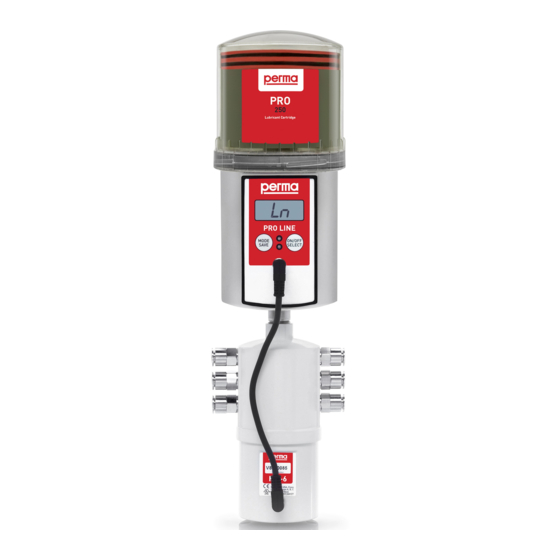
The perma Distributor PRO MP-6 Connection thread for attaching a lubricator of the perma PRO range Outlets 1 to 3 with connections for Outlets 4 to 6 with grease lines connections for grease lines Housing Connector connecting cable. Accessories Plug (4 pcs.) -
Page 53: Quick Reference Guide
Distributor PRO MP-6 Quick Reference Guide for the perma Distributor PRO MP-6 Assembly of perma Distributor PRO MP-6 (refer to chapter 3.1 and 3.2) Connect perma Distributor PRO MP-6 to the Lubricator (refer to chapter 3.3) Determine Discharge Period (refer to chapter 4.7) -
Page 54: General Information
Distributor PRO MP-6 General Information Delivery / Content Markings CE mark UL mark perma-tec GmbH & Co. KG Hammelburger Straße 21 Intended Usage pressure build-up of max. 25 bar (360 psi) must Any other usage, setting, addition, and variation is considered to be inappropriate! -
Page 55: Technical Data
Technical Data perma Distributor PRO MP-6 Length Diameter Weight 2 minimum Number of outlets Maximum working pressure Lubricants Ambient temperature Power supply Emission sound pressure level Connection thread for lubricators of the PRO range Connection thread for grease line Diameter of grease line... -
Page 56: Accessories
Design of the perma Distributor PRO MP-6 Accessories... -
Page 57: Mounting And Assembly Of The Distributor
Mounting and Assembly of the Distributor Mounting the Connections Distributor Housing Never loosen never open the housing. - Page 58 Combination of Distributor and Lubricator PRO range. Screw the distributor and the lubricator together. Attach both to the perma mounting device and install the mounting device. Direct Mounting of the Distributor onto the Lubricator Ensure correct and tight assembly of the connections and grease lines to avoid possible leakage.
- Page 59 Separate Mounting of Distributor and Lubricator tor. The grease line between lubricator, distributor and lubrication point must not exceed a total length of 5 meters (for details about temperature and lubricant please refer to operating instructions of PRO/PRO C chapter 2, chart 1). Ensure correct and tight assembly of the connections and grease lines to avoid possible leakage.
-
Page 60: Operation And Control
Distributor PRO MP-6 Operation and Control of the lubricator. Preparations Prior to Operation Setting into Operation the lubricator is set into operation! In addition, the Operating Instructions of the lubricator must be observed. - Page 61 Distributor PRO MP-6 During Operation Additional discharges and long machine standstills must always be taken into account with regard to the remaining discharge period of the lubrication system. Switching the Complete Lubrication System On PRO C ON/OFF Outlets Outlets...
- Page 62 Distributor PRO MP-6 Setting the Discharge Period Additional Discharge of the lubricant. switched on PRO C MODE MODE ON/OFF SELECT SAVE SELECT SAVE The time between two additional discharges is at least 30 seconds. Each additional long push of both The system records up to 5 additional discharges.
- Page 63 Distributor PRO MP-6 Activation of Outlets All outlets must be activated by the user before operation (factory setting = all outlets inactive). The Outlets Display Meaning/Description MODE ON/OFF SELECT SAVE SELECT Config. Outlets MODE SAVE ON/OFF SELECT SELECT Config.
- Page 64 Distributor PRO MP-6 4.10 Initialization of Distributor Automatic Initialization of the Distributor LED starts to blink and the lubrication system operates. Manual Initialization of the Distributor turned OFF PRO C PRO C MODE MODE ON/OFF SELECT SAVE SELECT SAVE Lubricator PRO When the manual initialization is completed, the display of the lubricator PRO shows “...
- Page 65 MODE ON/OFF SELECT SAVE SELECT SAVE Days Confi g. Config. Weeks Time Time PIN Months Outlets Outlets LC2500 LC2500 %Vol. perma PRO MP-6 perma PRO C MP-6 Confi g. Days Weeks Time Time PIN Months Outlets Outlets LC2500 LC2500 %Vol.
-
Page 66: Trouble Shooting
Distributor PRO MP-6 Trouble Shooting Error Messages of the Distributor on the Display of the Lubricator Error messages are acknowledged and reset by pushing the ON/OFF/SELECT or SELECT button. However, error messages “ ” and “ ” are automatically acknowledged when errors are corrected (see remedial measures). -
Page 67: Disposal
Distributor PRO MP-6 Disposal Service... -
Page 68: Accessories And Spare Parts
Accessories and Spare Parts genuine Spare parts and accessories must meet the technical requirements! This is always guaranteed with genuine spare parts and accessories from perma-tec. Spare parts Art. No. Illustration Cable PRO C M12 10 m... - Page 69 Spare parts Art. No. Illustration Plug...
-
Page 70: Declaration Of Conformity
2006/42/CE direttiva 2006/42/CE (u. Richtlinie 2014/30/EU) (and Directive 2014/30/EU) (et directive 2014/30/UE) (y directiva 2014/30/UE) (e direttiva 2014/30/UE) perma-tec GmbH & Co. KG Hammelburger Straße 21 97717 EUERDORF / GERMANY Der Hersteller The manufacturer Por la presente el fabri-... - Page 71 2006/42/CE direttiva 2006/42/CE (u. Richtlinie 2014/30/EU) (and Directive 2014/30/EU) (et directive 2014/30/UE) (y directiva 2014/30/UE) (e direttiva 2014/30/UE) perma-tec GmbH & Co. KG Hammelburger Straße 21 97717 EUERDORF / GERMANY Der Hersteller The manufacturer Por la presente el fabri-...
- Page 72 2006/42/CE direttiva 2006/42/CE (u. Richtlinie 2014/30/EU) (and Directive 2014/30/EU) (et directive 2014/30/UE) (y directiva 2014/30/UE) (e direttiva 2014/30/UE) perma-tec GmbH & Co. KG Hammelburger Straße 21 97717 EUERDORF / GERMANY Der Hersteller The manufacturer Por la presente el fabri-...
-
Page 73: Drilling Template
Drilling template Drilling template perma Distributor PRO MP-6... - Page 74 Drilling template Drilling template...
- Page 76 GmbH & Co. KG Hammelburger Str. 21...
Need help?
Do you have a question about the PRO 500 and is the answer not in the manual?
Questions and answers