Page 1
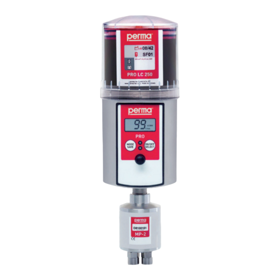
Translation of the Original Operating Instructions perma PRO 250 / 500 PRO C 250 / 500 PRO / PRO C LINE 250 / 500 PRO MP-6 Distributor PRO / PRO C MP-2 The Expert in Lubrications Solutions...
Page 2
GmbH & Co. KG This operating manual is valid for: perma PRO 250 / 500 perma PRO C 250 / 500 perma PRO / PRO C LINE 250 / 500 perma PRO MP-6 Distributor perma PRO / PRO C MP-2 Accessories and Spare Parts Declaration of conformity: •...
Page 3
Drilling template Chap. 4.3 perma PRO MP-6 Distributor...
Translation of the Original Operating Instructions perma PRO 250 / 500 Table of Contents The lubrication system perma PRO Quick reference guide Various 1.1 Delivery / Content 1.2 Storage 1.3 Markings 1.4 Intended Usage 1.5 Legal Requirements Safety Instructions 2.1 Persons Responsible for Safety 2.2 General Safety Instructions 2.3...
Page 6
- 1 - Lubrication System perma PRO Protection cover With bayonet catch for quick opening/closing. Content Description of the fi lling date and the contained lubricant. PRO LC unit Type (Lubrication Canister) Product type and size of PRO Cartridge, piston, spindle LC unit fi lled with lubricant. Display Informs about operating conditions, Red LED malfunctions, settings, and the Additional malfunction lubricant volume left in the indication. PRO LC unit. Push Button: ON/OFF/SELECT To turn system ON or OFF and to change settings.
Page 7
- 2 - perma PRO Quick Reference Guide for the Lubrication System perma PRO On this page you will find some important information for quick and easy operation and setting of the perma PRO. Before the first installation of the perma PRO, and whenever you need detailed instructions, you should read the complete Operating Manual which contains information that must be observed. Make sure to follow the instructions given in the chapter “Safety Notes”. Assembly of perma PRO / Exchange of PRO LC unit (refer to chapter 4 and 7) ♦ Mount the drive unit on the mounting plate and secure it at the three pre-drilled holes (see attached template). ♦ Insert a new battery set into the battery compartment (follow directions of the arrows). ♦ Place the PRO LC unit inside the cover and remove the plug of the PRO LC unit. ♦ Push the PRO LC unit into the cover until lubricant comes out of the opening.
Lubrication Canister ♦ In the following text, the “Lubrication Canister” will be called “PRO LC unit”. The user can order the PRO LC unit with different lubricants and in size 250 cm and 500 cm Usage of Safety Instructions All safety instructions in this operating manual are standardized. Danger Signs This sign warns you of any danger to people’s health or to subjects. Tips This sign alerts you to application tips which will help you in doing certain tasks quicker and safer. Delivery / Content ♦ perma PRO will be delivered according to customer specifi cations in regards to type of grease and size of PRO LC unit. The user must only assemble it and adjust the desired settings. ♦ Mounting device and screws included. ♦ Operating instructions and EC Conformity Declaration included. Upon delivery, make sure to check if the delivered goods correspond to your order. perma-tec GmbH & Co. KG will not accept liability for subsequent claims of any shortcomings. ♦ Please immediately forward any claims: of noticeable transport damage: directly to the forwarder. of noticeable faults, shortcomings or defects: directly to your perma distributor. Storage When the lubricators are not immediately installed, you must ensure appropriate storage conditions in dry, dust free places with a temperature of +20 °C ± 5 °C (+68 °F ± 9 °F).
- 4 - perma PRO Markings ♦ The lubricator perma PRO is clearly marked with a label (serial number) on the drive system and a label on the PRO LC unit. ♦ CE mark on the drive unit. UL mark on the drive unit: ♦ “This equipment is suitable for use in Class I, Div. 2, Groups A, B, C and D; or Non-Hazardous Locations only. Warning - Explosions Hazard - Substitution of components may impair suitability for Class I, Division 2. The lubricants dispensed by this equipment are to have flash points greater than 200 °F.“ ♦ Manufacturer: perma-tec GmbH & Co. KG Hammelburger Straße 21 97717 Euerdorf Germany Tel: +49 (0) 9704 609-0 E-mail: info@perma-tec.com Fax: +49 (0) 9704 609-50 Homepage: www.perma-tec.com Intended Usage The lubricator perma PRO ♦ immediately supplies all lubrication points with lubricant, at a pressure build-up of max. 25 bar (360 psi.), permanently, precisely and independent of temperature;...
the lubricator is opened by force while in operation; the lubricator is not mounted with the perma mounting device; the tube connection to the lubrication point was not carried out and attached correctly; ♦ Operate the lubricator only when it is in perfect condition. ♦ Retrofitting, changing, or reconstructing the lubricator is prohibited. perma-tec must be consulted first. ♦ Only original tube connections and connectors from perma-tec can be used on or with the lubrication system since these will withhold high pressures of up to 25 bar (360psi). ♦ Ambient media, especially chemically aggressive substances, can attack seals and plastic. Safety Information for perma PRO Safety during Installation and Maintenance ♦ Ensure that all workstations and traffic routes are clean and safe! ♦ Ensure that the relevant regulations and guidelines are adhered to when the installation or maintenance work is carried out in places where danger of falling exists. ♦ Ensure that the relevant safety and operating instructions are observed when the lubricators are installed or serviced on machines or in factories (i.e. to stop the machine). Safety when Handling the PRO LC unit ♦...
The dashed standard grease- and dotted low temperature-lines show the maximum values allowed. If your application is out of the specifi cation range shown in this diagram, please contact your local distributor. perma-tec cannot be held liable for these applications. Example: 1. The application temperature is +5 °C / +41 °F. What is the maximum tube length allowed for standard grease? Correct Answer: 3 m max. tube length for standard grease, 5 m max. tube length for low temp. grease (arrow...
Lubricators are available as 250 cm and 500 cm versions and they can be supplied with the lubricant requested by the customer. They consist of (refer to fi gure 2): Protection cover for the drive unit, re-usable. PRO LC unit (Lubrication Canister), can be supplied as 250 cm and 500 cm versions with the lubricant requested by the customer. Use only original perma PRO LC units! Battery set, consisting of two batteries. The batteries are not rechargeable and must be changed every time the PRO LC unit is replaced. Batteries can only be used once! Usage of perma-tec battery sets only! Drive unit, consisting of a gear motor, a pump system and an electronic unit for the control system, re-usable. fi gure 2...
- 8 - perma PRO Mounting and Assembly of the Lubrication System Mounting the Drive Unit onto a Fixing Device for Wall-Mounting ♦ Attach the supplied mounting device to the drive unit using the two enclosed hex head bolts (M6 x 16) and the two washers. ♦ Screw the mounting device with the drive unit onto a support of your system. The boring template of the three mounting screws (141.5 x 45) can be seen below in fi gure 3 or on the template that is included. You have to use at least three hexagon screws M6 x 25 (e.g. on metal ground). ♦ Before you connect the outlet of the drive unit to the lubricant tube, you have to make sure that the lubrication points and the complete lubricant tube is pre-lubricated with the same lubricant that is contained in the PRO LC unit. For that, perma-tec offers a 400 g lubrication cartridge for manually-operated grease presses with the requested lubricant. ♦ Connect the lubricant tube (connection G3/8) to the outlet of the drive unit and install the tube correctly between the outlet and the lubrication point. The lubricant tube must not be longer than fi ve meters. Make sure that you assemble the connections and lubricant tubes correctly and tightly to avoid possible leakage.
- 9 - Assembly of the Lubricator ♦ Insert the battery set into the drive unit (according to the direction of the arrow on the label). No function! Setting of PRO LC unit size is done via menu on display Battery set Catch Interlocking teeth fi gure 4 ♦ Place the PRO LC unit inside the protection cover and remove the plug of the PRO LC unit (refer to fi gure 5). Protection cover PRO LC unit Plug fi gure 5...
Page 15
- 10 - perma PRO ♦ Push the PRO LC unit into the protection cover until lubricant comes out of the opening (refer to fi gure 6). fi gure 6 ♦ Place the PRO LC unit with its protection cover on the drive-unit. Make sure that the catch locks and that the teeth of the PRO LC unit and the drive unit interlock (refer to fi gure 4 and fi gure 7). ♦ Turn the cover clockwise until the bayonet catch locks. fi gure 7...
PRO - 11 - Display and Control Elements of the Lubrication System Display Elements The operating status of the lubricator can be determined via the green or the red LED and via the display at the control unit (refer to figure 8) of the perma PRO. The perma PRO offers a menu-guided setting. Changes of the settings are shown on the display. Error messages, e.g. in case the pressure in the lubricant tube gets too high, are also indicated on the display. push-button MODE SAVE Red LED Green LED push-button ON/OFF SELECT Connector for distributor MP-6 figure 8 Function Indication on the Display The display is located on the control unit of the perma PRO (refer to figure 8, chapter 5.1). The display shows settings, operating conditions and error messages of the lubricator. In case of an error free operation of the lubrication system, the display shows the remaining volume of the mounted PRO LC unit in percent volume (% Vol.). Figure 9 shows an example of the displayed information if the PRO LC 500-unit is new and full. LC 500 %Vol.
Returns to original menu FUNCTION in current values saves selected values without saving changes display chart 3, figure 11, figure 12 Operation and Control Preparations ♦ Prior to the installation of the lubricator, the lubrication point and the complete connection tube must be sufficiently prelubricated with the same lubricant that the PRO LC unit contains. For this, perma-tec offers a 400 g lubrication cartridge for grease presses with the corresponding lubricant (refer to “Accessories and Spare Parts”). ♦ When installing the perma PRO, the supplied perma-tec mounting device should be used. ♦ The lubricant tube must be installed and mounted correctly. The length of the lubricant tube may not exceed a maximum of 5 meters and the tube must be a perma-tec product. ♦ Please check if the thread of the perma PRO (G3/8) corresponds to the connection thread of the lubrication point. If this is not the case, you can order a corresponding reducer or other parts from the perma accessory range. For the initial setting into operation of a perma PRO, the pump system in the drive unit is pre-filled with SF04 from perma’s standard range of lubricants. An exception is made with regard to lubricants for the food industry. A complete discharge of this pump filling is guaranteed after approx. 10 discharges (carry out additional discharges, if necessary). Prior to Operation ♦ Check all parts of the lubricator for obvious damages! ♦ Is the new PRO LC unit filled with the required lubricant? ♦ Did you insert a new battery set? ♦ Did you remove protection cover, disc and plug from drive unit (see chapter 1.2)?
PRO - 13 - Setting into Operation ♦ If necessary, mount the drive unit onto a fixing device for wall-mounting (refer to chapter 4.1). ♦ Insert the battery set into the drive unit and the PRO LC unit into the protection cover and close the complete system (refer to chapter 4.2 b - d). ♦ Determine the discharge period (refer to chapter 6.7). ♦ Set volume of PRO LC unit, discharge period, outlets of MP-6, and the PIN via buttons on display (refer to chapter 6.8). ♦ Switch-on the lubrication system (refer to chapter 6.5). ♦ Carry out an additional discharge (refer to chapter 6.8). If the drive motor has started and the green LED is lit, the lubricator has started to discharge. The display indicates the remaining volume (% Vol.) of the PRO LC unit. The operator must always check the customer-specific settings and if necessary change them before the lubricator is set into operation! During Operation ♦...
12.4 41.7 83.3 40.1 80.1 38.6 77.2 37.2 74.4 35.9 71.8 34.7 69.4 chart 4 Please take into account that in case of one or several additional discharges, the remaining discharge period of the lubrication system must be recalculated (refer to chapter 6.9). This also applies in case of a cut-off of the lubrication system due to a long machine standstill (e.g. weekends or annual holidays). You should also note the result of your calculation of the remaining discharge period in your lubrication and maintenance schedule. The perma SELECT software helps you to determine the discharge period. Visit our website www.perma-tec.com for a free download of this software.
PRO - 15 - Settings and Display for perma PRO (see caption on page 16) Display Meaning / Description MODE ON/OFF SAVE SELECT Display at delivery with attached PRO LC unit Time Shows discharge period Months PIN-reset MODE SAVE Change first digit Enter first digit of current PIN PIN “ ” at delivery MODE SAVE ON/OFF SELECT Change second digit Enter second digit of current PIN MODE SAVE ON/OFF...
Page 21
- 16 - perma PRO Caption for Chart on Left Side Instructions should be followed from top to bottom and from left to right (also refer to chart 3). The instructions correspond to the operating sequence on the turned-off lubrication system perma PRO. Configuration is also possible if perma PRO is On. Function short push long push blinking display go to Symbol chart 6 CONFIGURATION SECTIONS (see vertical bar, chart 5) I N T R O Info PIN Entry INTRO informs and asks for the current PIN. C O N F I G U R A T I O N M E N U E Settings can be changed in the configuration menu with its different sections (LC, Time, Outlets, PIN).
PRO - 17 - Low-Temperature Cut-Off of the Lubrication System The temperature range from 0 °C to - 19 °C (32 °F to -2.2 °F) is indicated by a blinking ice crystal symbol (refer to figure 16). In this temperature range the lubrication system perma PRO continues to operate without interruption. Please note, that in this temperature range an additional discharge is not possible! LC 500 %Vol. figure 16 Display with a blinking ice crystal (in this example with % Vol.) In order to protect the system from damage, the low-temperature cut-off of the lubrication system is automatically carried out by the control system and the built-in temperature sensor. If the temperature reaches or falls below - 20 °C (-4 °F), the lubricator is switched off by the low-temperature cut-off and the ice crystal symbol is permanently indicated on the display. The remaining volume is still displayed in % Vol. From this time onwards, the lubricant is no longer discharged. You have to take this fact into account if your system continues to operate in order to prevent damages! As soon as the temperature rises and reaches - 19 °C (-2.2 °F) or higher, the control system switches the...
- 18 - perma PRO Replacement of the PRO LC unit The Following Must Always Be Taken into Account If the replacement of an empty PRO LC unit becomes necessary, it will be indicated by a simultaneous blinking of the red and the green LED. Additionally, the display indicates that the PRO LC unit is empty (refer to figure 17). LC 500 %Vol. figure 17 If you replace the PRO LC unit, you also have to change the battery set. Otherwise, the correct operation...
Remove the used battery set from the drive unit. d) Insert the new battery set into the drive unit. Follow the directions of the arrows. e) Remove the plug of the PRO LC unit (refer to figure 5, chapter 4.2). f) Push the PRO LC unit into the protection cover until lubricant comes out of the opening (refer to figure 6, chapter 4.2). g) Place the new PRO LC unit on the drive unit, turn it until the catch locks and the teeth of the PRO LC unit and the drive unit interlock. The control system automatically recognizes the new PRO LC unit. The display indicates “ ”, if the perma PRO was switched off prior to the replacement of the PRO LC unit. Or it indicates “ % Vol.”, if the perma PRO was switched on before the replacement. You should only use completely full perma-tec PRO LC units, in order to guarantee a trouble-free operation. h) The lubrication system continues to operate with the previous setting of the discharge period. i) If required, change lubricator settings (see chapter 6.8). If the lubricator was ON before changing the LC unit, it will automatically resume operation with existing...
System does not detect No PRO LC unit installed Install an PRO LC unit the PRO LC unit No power supplied to the system No battery inserted or battery set Insert a new battery set and from the battery empty use a full PRO LC unit In addition to the above, the following malfunctions can occur when a perma MP-6 distributor is connected to the lubrication system: Lubrication system has been Excess motor current of the perma Replace perma MP-6 switched off MP-6 distributor Clear the blockage and ack- Excess motor current of the nowledge the fault by pushing...
PRO - 21 - Disposal Help us in protecting the environment and saving resources by recycling valuable raw material. Please follow your local waste disposal regulations. Service ♦ Please contact your local supplier for availability and cost of the following: Returning of the empty lubricator for environmentally safe recycling or disposal. exchange of battery set. exchange of PRO LC unit. to pre-set lubricator (LC / lubrication period / outlets)
Page 27
Translation of the Original Operating Instructions perma PRO C 250 / 500 Table of Contents The Lubrication System perma PRO C Quick Reference Guide Miscellaneous 1.1 Delivery / Content 1.2 Storage 1.3 Markings 1.4 Intended Usage 1.5 Legal Requirements Safety Instructions 2.1 Persons Responsible for Safety 2.2 General Safety Instructions 2.3...
Page 28
- 1 - Lubrication System perma PRO C Protection cover With bayonet catch for quick opening/closing. Content Description of the fi lling date and the contained lubricant. PRO LC unit Type (Lubrication Canister) Product type and size of Cartridge, piston, spindle fi lled with lubricant. PRO LC unit. Display Red LED Additional malfunction Informs about operating conditions, malfunctions, settings and the indication. lubricant volume left in the Push Button: MODE/SAVE PRO LC unit. Leads to the Confi guration Menu Green LED and saves the selected settings.
Page 29
Quick Reference Guide for the Lubrication System perma PRO C On this page you will find some important information for quick and easy operation and setting of the perma PRO C lubrication system. Before the first installation of the perma PRO C and whenever you need detailed instructions, you should read the complete Operating Manual which contains information that must be observed. Make sure to follow the instructions giving in the chapter “Safety Instructions”. Assembly of perma PRO C / Exchange of PRO LC unit (refer to chapter 4 and 7) ♦ Mount the drive unit on the mounting plate and secure it with the three pre-drilled holes (see attached template). ♦ Place the PRO LC unit inside the cover and remove the plug of the PRO LC unit. ♦ Push the PRO LC unit into the cover until lubricant comes out of the opening. ♦ Place the PRO LC unit with its cover on the drive-unit. Make sure that the catch locks and that the teeth of PRO LC unit and drive unit interlock.
- 3 - Miscellaneous About this Operating Manual ♦ This operating manual is intended for the safe operation of the perma PRO C automatic lubricator. It contains safety instructions which must be adhered to. ♦ Everyone who works on or with the lubricator must have access to this operating manual during their shift. They must also pay attention to all relevant instructions and notices. ♦ The operating manual must always be kept complete and in easy to read condition. Terms Used ♦ Lubrication system perma PRO C In the following text, the “lubrication system perma PRO C” will either be called “lubricator” or by its name “perma PRO C”. Lubrication Canister ♦ In the following text, the “Lubrication Canister” will be called “PRO LC unit”. The user can order the PRO LC unit with different lubricants and in sizes 250 cm and 500 cm Usage of Safety Instructions All safety instructions in this operating manual are standardized. Danger Signs This sign warns you of any danger to people’s health or to subjects. Tips This sign alerts you to application tips which will help you in doing certain tasks quicker and safer.
- 4 - perma PRO C Markings ♦ The lubricator perma PRO C is clearly marked with a label on the drive system (serial number) and a label on the PRO LC unit. ♦ CE mark on the drive unit ♦ Manufacturer: perma-tec GmbH & Co. KG Hammelburger Straße 21 97717 Euerdorf Germany Tel: +49 (0) 9704 609-0 E-mail: info@perma-tec.com Fax: +49 (0) 9704 609-50 Homepage: www.perma-tec.com Intended Usage The lubricator perma PRO C ♦ immediately supplies all lubrication points with lubricant, at a pressure build-up of max. 25 bar (360 psi), consistantly, precisely and independent of temperature; ♦ can be used for all lubrication points of sliding- and roller bearings, drive- and transport chains, sliding guideways, open gears and seals; ♦ must be used with a suitable protection box (refer to ”Accessories and Spare Parts”) if operated outside or around splashing water;...
the tube connection to the lubrication point was not carried out and attached correctly. ♦ Operate the lubricator only when it is in perfect condition. ♦ Retrofitting, changing, or reconstructing the lubricator is not allowed. perma-tec must be consulted first. ♦ Only original tube connections and connectors from perma-tec can be used on or with the lubrication system since these will withhold high pressures of up to 25 bar (360psi). ♦ Only an original connecting cable from perma-tec can be used to connect the lubricator to your control system and your equipment. ♦ Ambient media, especially chemically aggressive substances, can attack seals and plastic. Safety Information for perma PRO C Safety during Installation and Maintenance ♦ Ensure that all workstations and traffic routes are clean and safe! ♦ Ensure that the relevant regulations and guidelines are adhered to when the installation or maintenance work is carried out in places where danger of falling exists. ♦ Ensure that the relevant safety and operating instructions are observed when the lubricators are installed or serviced on machines or in factories (e.g. to stop the machine). Safety When Handling the PRO LC unit ♦...
The dashed standard grease- and dotted low temperature-lines show the maximum values allowed. If your application is out of the specifi cation range shown in this diagram, please contact your local distributor. perma-tec cannot be held liable for these applications. Example: 1. The application temperature is +5 °C/+41 °F. What is the maximum tube length allowed for standard grease? Correct Answer: 3 m max. tube length for standard grease, 5 m max. tube length for low temp. grease (arrow...
- 7 - Design of the PRO C Lubricator Lubricators are available as 250 cm and 500 cm versions and they can be supplied with the lubricant requested by the customer. They consist of (refer to fi gure 2): Protection cover for the drive unit, re-usable. PRO LC unit (Lubrication Canister), can be supplied as 250 cm and 500 cm versions with the lubricant requested by the customer. Use only original perma PRO LC units! Drive unit, consisting of a gear motor, a pump system, the connector for the connecting cable and an electronic unit for the control system re-usable. Connecting cable for linking the lubricator and the control system of your equipment (e.g. a PLC). fi gure 2...
- 8 - perma PRO C Assembly and Mounting of the Lubrication System Mounting the Drive Unit onto a Fixing Device for Wall-Mounting ♦ Attach the supplied mounting device to the drive unit using the two enclosed hex head bolts (M6 x 16) and the two washers. ♦ Screw the mounting device with the drive unit onto a support of your system. The boring template of the three mounting screws (141.5 x 45) can be seen below in fi gure 3 or on the template that is included. You have to use at least three hexagon screws M6 x 25 (e.g. on metal ground). ♦ Before you connect the outlet of the drive unit to the lubricant tube, you have to make sure that the lubrication points and the complete lubricant tube is pre-lubricated with the same lubricant that is contained in the PRO LC unit. For that, perma-tec offers a 400 g lubrication cartridge for manually-operated grease presses with the requested lubricant. ♦ Connect the lubricant tube (connection G3/8) to the outlet of the drive unit and install the tube correctly between the outlet and the lubrication point. The lubricant tube must not be longer than fi ve meters. Make sure that you assemble the connections and lubricant tubes correctly and tightly to avoid possible leakage.
- 9 - Assembly of the Lubricator ♦ Place the PRO LC unit inside the protection cover and remove the plug of the PRO LC unit (refer to figure 4). Protection cover PRO LC unit Plug fi gure 4 ♦ Push the PRO LC unit into the protection cover until lubricant comes out of the opening (refer to fi gure 5). fi gure 5...
- 10 - perma PRO C ♦ Place the PRO LC unit with its protection cover on the drive-unit. Make sure that the catch locks and that the teeth of the PRO LC unit and the drive unit interlock (refer to fi gure 6). ♦ Turn the cover clockwise until the bayonet catch locks. fi gure 6 Connect the Connecting Cable to the Lubricator ♦ Connect the four strands of the connecting cable to the control system (e.g. a PLC) of your equipment and pay attention to the pin assignment of the connector on the lubricator (refer to chart 2 and fi gure 7). ♦ Insulate the connected strands correctly. ♦ Insert the 4-pole connecting cable into the connector of the lubricator (refer to fi gure 6). ♦ Screw tight the connector socket of the connecting to the connector of the lubricator. Pin assignment of the connector on the lubricator fi gure 7 Pin no. of the connector...
- 11 - Display and Control Elements of the Lubrication System Display Elements The operating status of the lubricator can be determined via the green or the red LED and via the display at the control unit (refer to figure 8) of the perma PRO C. The perma PRO C offers a menu-guided setting. Changes of the settings are shown on the display. Error messages, e.g. in case the pressure in the lubricant tube gets too high, are also indicated on the display. MODE SAVE push-button red LED green LED SELECT Connector for push-button distributor MP-6 figure 8 Function Indication on the Display The display is located on the control unit of the perma PRO C (refer to figure 8, chapter 5.1). The display shows settings, operating conditions and error messages of the lubricator. In case of an error free operation of the lubrication system, the display shows the remaining volume of the mounted PRO LC unit in percent volume (% Vol.). Figure 9 shows an example of the displayed information if the PRO LC unit 500 is new and full. LC 500 %Vol. figure 9 The display cannot be switched off by the operator.
Operation and Control Preparations ♦ Prior to the installation of the lubricator, the lubrication point and the complete connection tube must be sufficiently pre-lubricated with the same lubricant that the PRO LC unit contains. For this, perma-tec offers a 400 g lubrication cartridge for grease presses with the corresponding lubricant (refer to ”Accessories and Spare Parts”). ♦ When installing the perma PRO C, the supplied perma-tec mounting device should be used. ♦ When connecting the perma PRO C to your control system, the supplied perma-tec connecting cable should be used. This connection may only be established by qualified personnel. ♦ The lubricant tube must be installed and mounted correctly. The length of the lubricant tube may not exceed a maximum of 5 meters and the tube must be a perma-tec product. ♦ Please check if the thread of the perma PRO C (G3/8) corresponds to the connection thread of the lubrication point. If this is not the case, you can order a corresponding reducer or other parts from the perma accessory line. For the initial setting into operation of a perma PRO C, the pump system in the drive unit is pre-filled with SF04 from perma’s standard range of lubricants. An exception is made with regard to lubricants for the food industry. A complete discharge of this pump filling is guaranteed after approx. 10 discharges (carry out additional dis- charges, if necessary). Prior to Operation ♦ Check all parts of the lubricator for obvious damages! ♦ Is the new PRO LC unit filled with the required lubricant? ♦ Is the connecting cable connected to the control system of your equipment and is the supply voltage (DC 15 V to 30 V) applied? ♦ Did you remove protection cover, disc and plug from drive unit (see chapter 1.2)? ♦ Did you assemble and mount all of the parts correctly and tightly?
♦ If your control system indicates a malfunction, you have to determine its cause directly via the display of the perma PRO C. You can check for possible causes using the trouble shooting guide (refer to chart 8, chapter 8.3). If the fault cannot be fixed, please contact your local supplier for technical support. Additional discharges and long machine standstills must always be taken into account with regard to the remaining discharge period of the lubricator. Switching the Lubrication System On To turn the lubrication system on, you have to switch on the supply voltage for the perma PRO C. The indication (“ ”) on the display is replaced by an indication of the remaining volume – e.g. % VOL (with a new PRO LC unit) (see figure 13). The green LED starts blinking and the malfunction output sends a “High” signal (system OK) to the connected control system. Switch-on of the supply voltage by the control LC 500 system %Vol. figure 13 Switching the Lubrication System Off To switch the lubrication system off (refer to figure 14) you have to switch off the supply voltage of the perma PRO C. The display no longer indicates the remaining volume – % VOL – but indicates (“ ”) instead. When the lubrication system is switched off, all of the settings are saved. This means that if you start the lubricator again, it will take up the operation at the point where it had been switched off. The fault output sends a “Low” signal (system not working) to the control system. LC 500 %Vol. figure 14...
12.4 41.7 83.3 40.1 80.1 38.6 77.2 37.2 74.4 35.9 71.8 34.7 69.4 chart 5 Please take into account that in case of one or several additional discharges, the remaining discharge period of the lubrication system must be recalculated (refer to chapter 6.9). This also applies in case of a cut-off of the lubrication system due to a long machine standstill (e.g. weekends or annual holidays). You should also note the result of your calculation of the remaining discharge period in your lubrication and maintenance schedule. The perma SELECT software helps you to determine the discharge period. Visit our website www.perma-tec.com for a free download of this software.
Page 42
- 15 - Settings and Display for perma PRO C (see caption on page 16) Display Meaning/Description MODE SELECT SAVE Display at delivery with attached PRO LC unit Time Shows discharge period Months PIN-reset MODE SAVE Change first digit Enter first digit of current PIN PIN “ ” at delivery MODE SAVE SELECT Change second digit Enter second digit of current PIN MODE SAVE SELECT Change from LC500 to LC250 Config. Set LC unit size MODE...
Page 43
- 16 - perma PRO C Caption for Chart on Left Side Instructions should be followed from top to bottom and from left to right (also refer to chart 4). The instructions correspond to the operating sequence on the turned off lubrication system perma PRO C. Configuration is also possible if perma PRO C is On. Function short push long push blinking display go to Symbol chart 7 CONFIGURATION SECTIONS (see vertical bar, chart 6) I N T R O Info PIN Entry INTRO informs and asks for the current PIN. C O N F I G U R A T I O N M E N U E Settings can be changed in the configuration menu with its different sections (LC, Time, Outlets, PIN).
- 17 - Low-Temperature Cut-Off of the Lubrication System The temperature range from 0 °C to - 19 °C (32 °F to -2.2 °F) is indicated by a blinking ice crystal symbol (refer to figure 16). In this temperature range the lubrication system perma PRO C continues to operate without interruption. Please note, that in this temperature range an additional discharge is not possible! LC 500 %Vol. figure 16 Display with a blinking ice crystal (in this example with % Vol.) In order to protect the system from damage, the low-temperature cut-off of the lubrication system is automatically carried out by the control system and the built-in temperature sensor. If the temperature reaches or falls below - 20 °C (-4 °F), the lubricator is switched off by the low-temperature cut-off and the ice crystal symbol is permanently indicated on the display. The remaining volume is still displayed in % Vol. From this time onwards, the lubricant is no longer discharged. You have to take this fact into account if your system continues to operate in order to prevent damages! As soon as the temperature rises and reaches - 19 °C (-2.2 °F) or higher, the control system switches the...
- 18 - perma PRO C 6.10 Impulse Mode via the Connected Control System Discharge of lubricator PRO C can also be triggered via the attached control system. In this case, the lubricator discharges 0.5 cm lubricant to the lubrication point every time it is switched on. For this, you have to switch on the supply voltage via your control system for at least 14 minutes and then you have to switch it off for at least 20 seconds. The minimum operating time of 14 minutes is due to the possibility to connect the perma PRO C to the distributor perma MP-6. This distributor is able to supply lubricant to up to six lubrication points. This means that the distributor needs a minimum operating time of 14 minutes to be able to supply 1.0 cm lubricant to every open distributor outlet. If operated as a single-point lubrication system, the minimum operating time is reduced to 1 minute and the discharge amount per impulse = 0.5 cm For an activation of the perma PRO C lubricator via your control system, you need to set the lubricator to impulse mode via the configuration menu (refer to chapter 6.8). For this, you have to select the setting “ “ Days in the setting mode “Days” (refer to figure 17). Days Days Confi g. Config. Weeks Time Time PIN Time Months Outlets LC2500 LC2500 %Vol.
Remove the empty PRO LC unit. The display indicates “ ” and the red LED is blinking. c) Remove the plug of the PRO LC unit (refer to figure 4, chapter 4.2). d) Push the PRO LC unit into the protection cover until lubricant comes out of the opening (refer to figure 5, chapter 4.2). e) Place a new PRO LC unit on the drive unit, turn it until the catch locks and the teeth of the PRO LC unit and the drive unit interlock. The control system of the perma PRO C automatically recognizes the new PRO LC unit and the display indicates “ ”, if the perma PRO C was switched off prior to the replacement of the PRO LC unit. Or it indicates “ % Vol.”, if the perma PRO C was switched on before the replacement. You should only use completely full perma PRO LC units in order to guarantee a trouble-free operation. f) The lubrication system continues to operate with the previous setting of the discharge period. g) If required, change lubricator settings. Refer to chapter 6.8 or to chapter 6.10 in case of an impulse mode of the lubricator. If the lubricator was ON before changing the LC unit, it will automatically resume operation with existing settings.
SELECT button Lubricator has been switched off Drive mechanism is defective Exchange the drive unit System does not detect No PRO LC unit installed Install an PRO LC unit the PRO LC unit In addition to the above, the following malfunctions can occur when a perma MP-6 distributor is connected to the lubrication system: Lubrication system has been Excess motor current of the Replace perma MP-6 switched off perma MP-6 distributor Clear the blockage and ack- Excess motor current of the nowledge the fault by pushing...
- 21 - Disposal Help us in protecting the environment and saving resources by recycling valuable raw material. Please follow your local waste disposal regulations. Service ♦ Please contact your local supplier for availability and cost of the following: Returning of the empty lubricator for environmentally safe recycling or disposal Exchange of the PRO LC unit To pre-set lubricator (LC / lubrication period / outlets)
Page 49
Months Outlets Outlets LC2500 LC2500 LC 500 discharge period“ %Vol. Lubrication system turned on (ON) Differences perma PRO / PRO C LINE (compared to perma PRO / PRO C) The pause time between two discharges and the discharge amounts from 1 to 9 strokes can be programmed for each individual outlet. After each pause time, the system will conduct a discharge with as many strokes as programmed for this outlet. The following settings and displays are new (operating instructions perma PRO / PRO C chapter 6.8): ♦ Number of strokes per discharge (1 stroke = 0.5 cm ♦ Pause time in days between discharges ♦ Display of discharge time remaining The chart on the following page will assist with settings. Total discharge period The longest discharge period that the system can be programmed for is 24 months (in order to stay within the maximum lubricant service life).
Page 50
Settings and Display for perma PRO / PRO C LINE Display Meaning / Description MODE ON/OFF SELECT SAVE SELECT Days Confi g. Weeks Time Time PIN Display at delivery with Months Outlets LC2500 LC2500 attached PRO LC unit %Vol. Confi g. Days Weeks Weeks Time...
Page 51
Translation of the Original Operating Instructions perma MP-6 Distributor Table of Contents The distributor perma MP-6 Quick Reference Guide Miscellaneous 1.1 Delivery / Content 1.2 Markings 1.3 Intended Usage 1.4 Legal Requirements Safety Instructions 2.1 Persons Responsible for Safety 2.2 General Safety Instructions 2.3 Safety Information for perma MP-6 Technical Data 3.1 Design of the perma MP-6 Distributor 3.2...
Page 52
- 1 - The Distributor perma MP-6 Connection thread for attaching a lubricator of the perma PRO range. Outlets 1 to 3 with connections for Outlets 4 to 6 with grease lines connections for grease lines Housing contains drive unit and distribution system Connector used for plugging in the connecting cable. Accessories max. 6 mm Plug (4 pcs.) for sealing the outlets that are 6 connections not used.
Page 53
- 2 - perma PRO MP-6 Distributor Quick Reference Guide for the Distributor perma MP-6 On this page you will find some important information for quick and easy operation and setting of your perma MP-6 dis- tributor. Before the perma MP-6 is used, prior to the assembly of the distributor with a lubricator of the perma PRO range and whenever you need detailed information, you should read the complete Operating Instructions, which contain infor- mation that must be observed. Make sure to follow the instructions given in the chapter “Safety Instructions”. Additionally, you have to observe the Operating Instructions of the connected lubricator. Assembly of perma MP-6 (refer to chapter 4.1 and 4.2) ♦ Screw connections into the outlets that you want to activate and seal the other outlets with plugs. Connect perma MP-6 to the Lubricator (refer to chapter 4.3) ♦ Screw the lubricator tightly into the thread of the distributor. ♦ Position the rear sides of the lubricator and the distributor at one level.
♦ Everyone who works on or with the perma MP-6 distributor must have access to this operating manual during their shift. They must also pay attention to all relevant instructions and notices. ♦ The operating manual must always be kept complete and in easy to read condition. ♦ In addition, the operating manual of the connected lubricator must be observed. Terms Used ♦ perma PRO MP-6 Distributor In the following text, the “perma PRO MP-6 distributor” will either be called “distributor” or by its name “perma MP-6”. ♦ Lubricator of the perma PRO range In the following text, the “lubricator of the perma PRO range” will be called “lubricator”. Usage of Saftey Instructions All safety instructions in this operating manual are standardized. Danger Signs This sign warns you of any danger to people’s health or to subjects. Tips This sign alerts you to application tips which will help you in doing certain tasks quicker and safer. Delivery / Content ♦ The perma MP-6 is a distributor for the lubricators of the perma PRO range. The distributor is equipped with all necessary components and accessories and can be set and fitted according to customer requirements.
- 4 - perma PRO MP-6 Distributor Markings ♦ The perma MP-6 distributor is clearly marked with a serial number and a label on the drive unit. ♦ CE mark on the drive unit. ♦ UL mark on the drive unit: “This equipment is suitable for use in Class I, Div. 2, Groups A, B, C and D; or Non-Hazardous Locations only. Warning - Explosions Hazard - Substitution of components may impair suitability for Class I, Division 2.” The lubricants dispensed by this equipment are to have flash points greater than 200 °F.“ ♦ Manufacturer: perma-tec GmbH & Co. KG Hammelburger Straße 21 97717 Euerdorf Germany Tel: +49 (0) 9704 609-0 E-mail: info@perma-tec.com Fax: +49 (0) 9704 609-50 Homepage: www.perma-tec.com Intended Usage The distributor perma MP-6 ♦ may only be used together with a lubricator of the perma PRO range; ♦ must be connected to the lubricator using the connecting cable; ♦ immediately supplies up to six lubrication points with lubricant, at a pressure build-up of max. 25 bar (360 psi), constantly, precisely and independent of temperature;...
the distributor setting/variation is incorrect; the distributor is opened by force while in operation; the distributor is not mounted with the perma mounting device and the lubricator; the tube connection to the lubrication point was not carried out and attached correctly. ♦ Operate the distributor only when it is in perfect condition. ♦ Retrofitting, changing, or reconstructing the distributor is not allowed. perma-tec must be consulted first. ♦ Only original tube connections and connectors from perma-tec can be used on or with the distributor since these will withhold high pressures of up to 25 bar (360psi). ♦ Ambient media, especially chemically aggressive substances, can attack seals and plastic. Safety Information for perma MP-6 Safety during Installation and Maintenance ♦ Ensure that all workstations and traffic routes are clean and safe! ♦ Ensure that the relevant regulations and guidelines are adhered to when the installation or maintenance work is carried out in places where danger of falling exists. ♦ Ensure that the relevant safety and operating instructions are observed when the lubricators and distributors are installed or serviced on machines or in factories (i.e. to stop the machine). Safety When Handling Lubricants ♦ Avoid contact of lubricant with eyes, skin, and clothing! ♦...
- 6 - perma PRO MP-6 Distributor Technical Data perma PRO MP-6 Distributor Length 148 mm Diameter 64 mm Weight ca. 0.960 kg 2 minimum Number of outlets 6 maximum Maximum working pressure 25 bar (360 psi) Lubricants Greases up to rated consistency NLGI 2 Ambient temperature - 20 °C to +60 °C / - 4 °F to +140 °F Power supply from the lubricator via connecting cable Emission sound pressure level < 70 dB(A) Connection thread for lubricators...
- 7 - Design of the perma MP-6 Distributor Each distributor (refer to fi gure 2) is supplied with all necessary accessories (refer to fi gure 3). The user has to install the required connections or plugs and must connect the distributor to a lubricator of the perma PRO range. The perma MP-6 distributor consists of: Housing containing the drive unit and the distribution system (max. 6 outlets). fi gure 2 Accessories max. 6 mm max. 6 mm Connections (6 pcs.) for grease lines Plugs (4 pcs.) for sealing the outlets which are not used. Connecting cable (short) for power supply of the distributor and for communication between distributor and lubricator. fi gure 3...
- 8 - perma PRO MP-6 Distributor Assembly and Mounting of the Distributor Mounting the Connections ♦ Chose the number (6 max.) and the position of the outlets that you intend to use. ♦ Screw the connections tightly (max. torque of 2 Nm) into the outlets to be opened (refer to fi gure 4). ♦ Seal all the remaining outlets using the enclosed plugs. fi gure 4 Distributor Housing Never loosen these screws at the bottom of the distributor and never open the housing. fi gure 5...
- 9 - Combination of Distributor and Lubricator After you have equipped the perma MP-6 with connections, you can connect the distributor to a lubricator of the PRO range. Screw the distributor and the lubricator together. Attach both to the perma mounting device and install the mounting device. Direct Mounting of the Distributor onto the Lubricator ♦ Before you connect the distributor and the lubricator, all lubrication points must be pre-greased and all grease lines must be pre-fi lled with the same lubricant that the PRO LC unit contains. For that, perma-tec offers a 400 g lubrication cartridge for manually-operated grease presses with the requested lubricant.
Page 61
- 10 - perma PRO MP-6 Distributor Separate Mounting of Distributor and Lubricator Separate mounting of the distributor and the lubricator is possible. For this, perma-tec offers an additional mounting device, the necessary tube connections and a longer con- necting cable (refer to “Accessories and Spare Parts”). Attach the lubricator of the PRO range to your system as described in its Operating Instructions and mount the distributor as follows: ♦ Attach the mounting device to the distributor using the enclosed hex head bolts (M6 x 16) and the washers. ♦ Screw the mounting device with the distributor onto a support of your system. For the bore position of the four fi xing screws refer to fi gure 7 below. At least four hexagon screws M6 x 25 must be used (e.g. on metal ground). ♦ Before you connect the outlets of the distributor to any grease lines and hoses you have to pre-lubricate all lubrication points and pre-fi ll all grease lines with the same lubricant that is contained in the PRO LC unit of the lubricator. For that, perma-tec offers a 400 g lubrication cartridge for manually-operated grease presses with the requested lubricant. ♦ Fit the reducer coupling G3/8i to G1/8i f. tube oØ 8 mm (Part no. 101545) and the tube connector G1/8o for tube oØ 8 mm straight (Part no. 101570) on the lubricator. ♦ Fit the tube connector G3/8o for tube oØ 8 mm straight (Part no. 101498) on the distributor. ♦ Connect the distributor to the PRO lubricator with the grease line. Maximum tube length 2 meters (Ø 8 x 1.5, inner-Ø 5 mm). ♦ Connect the grease lines to the connections of the distributor and install them correctly between the distributor and the lubrication point. The grease line between lubricator, distributor and lubrication point...
- 11 - Operation and Control Please note that the perma MP-6 distributor may only be connected to a lubricator of the PRO range. If you combine the distributor with a PRO lubricator, you also have to observe the Operating Instructions of the lubricator. Preparations ♦ Prior to installing the lubrication system (lubricator and distributor), all lubrication points must be pre-lubricated and all grease lines must be sufficiently pre-filled with the same lubricant that is contained in the LC unit of the lubricator. For this, perma-tec offers a 400 g lubrication cartridge for grease presses with the corres- ponding lubricant (refer to “Accessories and Spare Parts”). ♦ When installing the lubrication system, the supplied perma-tec mounting device should be used. The lubricator and the distributor should be fixed to this mounting device (refer to chapter 4.3). ♦ The grease lines must be installed and mounted correctly. Grease lines must be from perma-tec and cannot exceed a length of 5 meters per outlet. For the initial setting into operation of a lubricator, the pump system in the drive unit is pre-filled with SF04 from perma’s standard range of lubricants. An exception is made with regard to lubricants for the food industry. A complete discharge of this pump filling is guaranteed after approx. 10 discharges (carry out additional discharges, if necessary). Prior to Operation ♦ Check all parts of the distributor and the complete lubrication system for obvious damages! ♦ Did you correctly assemble, mount, and tighten all of the connections and the plugs of the distributor? ♦ Are the grease lines, coming from the distributor, mounted correctly on the connections? ♦ Was the drive unit of the lubricator set to the discharge period requested by the operator while taking into account the required discharge volume and the number of open outlets? ♦ Did you correctly assemble, mount and tighten all of the parts? Setting into Operation ♦...
- 12 - perma PRO MP-6 Distributor During Operation ♦ Carry out regular inspections during operation. You should pay special attention to leakage, to the condition of the distributor, and the complete lubrication system! ♦ Regularly check the condition of the grease lines and the connections! ♦ Regularly check the filling level of the transparent PRO LC unit of the lubricator! ♦ After one or several additional discharges, you have to calculate the remaining discharge period and mark it in your lubrication and maintenance schedule. ♦ If a malfunction is indicated on the display, you can determine the cause using the trouble shooting guide (refer to chart 3, chapter 6.2). If the fault cannot be fixed, please contact your supplier for technical support. Additional discharges and long machine standstills must always be taken into account with regard to the remaining discharge period of the lubrication system.
- 13 - Setting the Discharge Period The discharge period can be set any time via the lubricator and without having to interrupt the operation. It does not matter if the lubrication system is switched on or off, since the system switches back to its original operating status after the changes have been made. For a precise setting of the discharge period, please refer to the Operating Instructions of the connected lubricator. Additional Discharge With an additional discharge, all open lubrication points can be supplied with an additional amount of the lubricant. Each open outlet provides 1.0 cm of the lubricant. For an additional discharge, the lubrication system must be switched on and you have to press and hold down both buttons of the lubricator simultaneously (refer to figure 10). An additional discharge is carried out at each activated outlet (it takes approx. 30 seconds between outlets). This means that if all outlets are open, the process of an additional discharge takes maximum 14 minutes. PRO C MODE MODE ON/OFF SELECT SAVE SELECT SAVE figure 10 For an additional discharge, press both buttons of the lubricator and hold them down. An additional discharge is only possible at temperatures above 0 °C (32 °F). Every additional discharge reduces the remaining discharge period since an increased amount of the lubricant has been supplied. This must be taken into account in your lubrication and maintenance schedule. The time between two additional discharges is at least 30 seconds. Each additional long push of both buttons (figure 10) will be recorded by the system and leads to further additional discharges on all outlets.
- 14 - perma PRO MP-6 Distributor Activation of Outlets Chart 2 below only includes part of the complete Operating Instructions. Therefore please also refer to the Operating Instructions (refer to chapter 6.8) of your lubricator. All outlets must be activated by the user before operation (factory setting = all outlets inactive). The lubricator must be turned off before carrying out initialization. Outlets Chart 2 shows an example for the configuration of outlets: All outlets are inactive (factory setting). You want to activate outlets 1, 3, 5. Outlets 2, 4, and 6 should be inactive (closed). Display Meaning/Description MODE...
- 15 - 5.10 Initialization of Distributor Automatic Initialization of the Distributor In order to supply lubricant to all open outlets and to ensure a correct operation of the perma MP-6, an automatic initialization of the lubrication system is carried out when the system is switched on for the first time. During initialization the system recognizes the activated outlets. Outlets (represented by squares) in the display are blinking. Activated outlets (squares) will be blackened, inactive outlets (squares) are blank. When initialization is finished, the display shows the remaining volume and activated outlets. The green LED starts to blink and the lubrication system operates. Manual Initialization of the Distributor If you connect a new distributor to the lubricator (exchange old distributor with new one), you must do a manual initialization of the perma MP-6. The system recognizes the activated outlets. Outlets (represented by squares) in...
- 16 - perma PRO MP-6 Distributor Trouble Shooting Error Messages of the Distributor on the Display of the Lubricator Possible errors of the distributor and the complete lubrication system are detected by the electronic control unit and are indicated on the display of the lubricator. For example, if the error message is shown on the display, the required pressure at the second connected lubrication point exceeds 25 bar (360psi). This means that this lubrication point is no longer supplied with lubricant. The distributor still provides lubricant to all other activated lubrication points. Correct the malfunction of the second lubrication point (e.g. grease line bent or blocked) and acknowledge it by pushing the ON/OFF/SELECT button on the lubricator PRO or the SELECT button on lubricator PRO C. Error messages are acknowledged and reset by pushing the ON/OFF/SELECT or SELECT button. Trouble Shooting Guide If there are malfunctions during the operation of the distributor or the lubrication system, please check for pos- sible causes using the following chart (refer to chart 3). If you have to deal with a malfunction that is not listed...
- 17 - Disposal Help us in protecting the environment and saving resources by recycling valuable raw material. Please follow the individual waste disposal regulations in your country. Service ♦ If you wish to return a perma MP-6 that is no longer used, please check with your local supplier for possible return to recycle or dispose of the used parts in an environmentally safe manner.
Page 69
Translation of the Original Operating Instructions perma PRO / PRO C MP-2 The perma PRO / PRO C MP-2 lubrication system supplies 2 lubrication points with the same amount of lubricant. It is mainly used for lubrication on motors, fans, and pumps.
Page 70
- 1 - Determine Discharge Period Check the lubrication specifications of your application for the correct discharge amount and times per lubrication point that the PRO / PRO C MP-2 distributor outlet should discharge. If necessary, calculate this amount in per 100 operating hours. Double this figure to get the total lubricant amount in cm for 100 operating hours (two lubrication points receive the same amount of lubricant). Go to the chart in the PRO / PRO C operating manual (chapter 6.7). Find your previously determined total lubricant amount in the chart. The chart will tell you the correct lubricator setting depending on the size of the PRO LC unit. Calculation example: Lubrication data listed on the specification plate of an electric motor: 150 cm / 4000 h lubricant per bearing (2 bearings!) This amounts to 3.75 cm per 100 operating hours. Each outlet of the distributor PRO / PRO C MP-2 must discharge 3.75 cm per 100 hours. Total discharge amount that the lubrication system must discharge: 7.5 cm per 100 operating hours (3.75 cm times 2 outlets / 100 h) The chart on chapter 6.7 of the PRO / PRO C operating manual shows the following setting:...
Page 71
- 2 - perma PRO / PRO C MP-2 Installation Dimensions 102 mm Ø 92 mm DO NOT disconnect distributor ATTENTION! DO NOT loosen distributor assembly screws Ø 49 mm Assembly max. 6 mm max. 6 mm 2 connection threads G1/8 for angled or straight connecting parts...
Page 72
Accessories and Spare Parts Due to the high pressure of up to 25 bar (360 psi), you should only use genuine spare parts and accessories from perma-tec in order to ensure a reliable operation of the distributor and the complete lubrication system. This especially applies to connections and lubricant tubes. Spare parts and accessories must meet the technical requirements! This is always guaranteed with genuine spare parts and accessories from perma-tec. Spare parts Part no. Illustration PRO LC 250 on request fi lled with lubricant PRO LC 500 on request...
Page 73
103288 max. 6 mm Tube connector G1/8a for tube 101570 aØ 8 mm straight max. 6 mm Tube connector G1/8o for tube 101571 oØ 8 mm 90° - rotary type Reducer coupling G3/8i to G1/8i f. tube 101545 oØ 8 mm (nickel-plated) Tube connector G3/8o for tube 101498 oØ 8 mm straight PRO MP-6 Connecting cable (14 cm) 106940 PRO MP-6 Connecting cable (2 m) 106941 perma PRO Mounting Device 101568 (for wall mounting) Grease cartridge 400 g fi lled with to be used for pre-fi lling grease on request lines with a grease gun Tube black up to +80 °C oØ 8 mm x iØ 5 mm - for PRO 101569 with different lengths PRO Protection box single (steel) 101527 PRO Protection box single (plastic) 101548 PRO Protection box double (steel) 101500...
Page 74
Déclaration CE de Declaración de Dichiarazione di erklärung Conformity conformité conformidad CE conformità CE perma-tec GmbH & Co. KG Hammelburger Str. 21 97717 EUERDORF | GERMANY In der Gemeinschaft Person residing Personne établie Persona con resi- Persona residente ansässige Person, within the dans la Communauté...
Page 75
Déclaration CE de Declaración de Dichiarazione di erklärung Conformity conformité conformidad CE conformità CE perma-tec GmbH & Co. KG Hammelburger Str. 21 97717 EUERDORF | GERMANY In der Gemeinschaft Person residing Personne établie Persona con resi- Persona residente ansässige Person, within the dans la Communauté...
Page 76
Déclaration CE de Declaración de Dichiarazione di erklärung Conformity conformité conformidad CE conformità CE perma-tec GmbH & Co. KG Hammelburger Str. 21 97717 EUERDORF | GERMANY In der Gemeinschaft Person residing Personne établie Persona con resi- Persona residente ansässige Person, within the dans la Communauté...
Page 77
Drilling template Chap. 4.3 perma PRO MP-6 Distributor...
Page 79
PRO MP-2 PRO C MP-2 Type: Type: Type: Tipo Tipo: PRO 250 MP-2 / PRO 500 MP-2 PRO C 250 MP-2 / PRO C 500 MP-2 Produktidenti- Product identifi ca- Numéro d´identi- Número Codice identifi ca- de identifi -...
Page 80
GmbH & Co. KG Hammelburger Str. 21 97717 EUERDORF GERMANY Tel.: +49 9704 609-0 info@perma-tec.com www.perma-tec.com...
Need help?
Do you have a question about the PRO 250 and is the answer not in the manual?
Questions and answers