Table of Contents
Advertisement
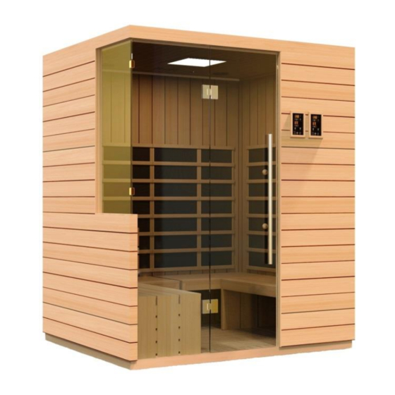
DYN-5830 / DYN-5860
3 & 6 Person FAR Infrared Saunas
Owner's Manual
CARBON MODEL SAUNAS
SAUNAS ARE FOR INDOOR USE ONLY
120VAC 20AMP Single Dedicated Circuit Required
(3 Person Model)
120VAC 20AMP Dual Dedicated Circuits Required
(6 Person Model)
Carefully and thoroughly read this Owner's Manual before using/operating the
sauna. We recommend keeping this Owner's Manual for regular review and
future reference.
Advertisement
Table of Contents

Related Manuals for Dynamic Saunas DYN-5830


Summary of Contents for Dynamic Saunas DYN-5830
- Page 1 DYN-5830 / DYN-5860 3 & 6 Person FAR Infrared Saunas Owner’s Manual CARBON MODEL SAUNAS SAUNAS ARE FOR INDOOR USE ONLY 120VAC 20AMP Single Dedicated Circuit Required (3 Person Model) 120VAC 20AMP Dual Dedicated Circuits Required (6 Person Model) Carefully and thoroughly read this Owner’s Manual before using/operating the sauna.
- Page 2 What Are Infrared Rays? Infrared is the band of light we perceive as heat. We cannot see this band of light with the naked eye, but we can feel this type of light in the form of heat. Our sun produces most of its energy output in the infrared segment of the spectrum.
- Page 3 Health Benefits Include, But Are Not Limited To: *Pain relief from Rheumatoid Arthritis *Relaxes muscle spasms *Increases blood circulation *Cardiovascular conditioning *Clears rashes, acne *Reduces cellulite *Removes toxins and mineral waste *Reduces stress and fatigue *Enhances skin tone DISCLAIMER The infrared rays emitted by your sauna are reported to offer a wide range of possible therapeutic benefits based on research completed over the last 40 years from all around the world.
- Page 4 as “power frequency” fields. Hertz is the unit for measuring the frequency of fields in the number of wave cycles each second. The lower the frequency of a field, the lower its energy. Power frequency fields are low frequency fields and have low energy levels. Microwave and x-ray fields are high frequency fields and have high energy levels.
- Page 5 *PLEASE READ INSTRUCTIONS THOROUGHLY BEFORE ASSEMBLY* DYN-5830-01 *THE ABOVE ASSEMBLY DIAGRAM IS FOR A QUICK REFERENCE VISUAL GUIDE ONLY. ALL SAUNA MODELS MAY NOT BE SHOWN. PARTS AND ACCESSORIES DO VARY AND ARE SUBJECT TO CHANGE. Page 4...
- Page 6 *PLEASE READ INSTRUCTIONS THOROUGHLY BEFORE ASSEMBLY* DYN-5860-01 *THE ABOVE ASSEMBLY DIAGRAM IS FOR A QUICK REFERENCE VISUAL GUIDE ONLY. ALL SAUNA MODELS MAY NOT BE SHOWN. PARTS AND ACCESSORIES DO VARY AND ARE SUBJECT TO CHANGE. Page 5...
-
Page 7: Table Of Contents
TABLE OF CONTENTS Product Introduction Parts Description Assembly Instructions Operating the Sauna Tips for Using your Sauna Safety Instructions Safeguards for your Sauna Troubleshooting Guide Warranty Warranty Card WARNING: Visually inspect all heaters before assembly to make sure they are not damaged. -
Page 8: Parts Description
*PLEASE READ INSTRUCTIONS THOROUGHLY BEFORE ASSEMBLY* PARTS DESCRIPTION *THE ABOVE ASSEMBLY DIAGRAM IS FOR A QUICK REFERENCE VISUAL GUIDE ONLY. ALL SAUNA MODELS MAY NOT BE SHOWN. PARTS AND ACCESSORIES DO VARY AND ARE SUBJECT TO CHANGE. Page 7... - Page 9 *PLEASE READ INSTRUCTIONS THOROUGHLY BEFORE ASSEMBLY* PARTS DESCRIPTION *THE ABOVE ASSEMBLY DIAGRAM IS FOR A QUICK REFERENCE VISUAL GUIDE ONLY. ALL SAUNA MODELS MAY NOT BE SHOWN. PARTS AND ACCESSORIES DO VARY AND ARE SUBJECT TO CHANGE. Page 8...
- Page 10 Power Supply (Control Box) The POWER SUPPLY is the control center of the sauna room. It is installed on the topside of the ROOF PANEL and has inputs/outputs connected to it. See Figure 1. Model DYN-5860-01 will have two power supplies of which you will need two separate dedicated 120V 20AMP outlets.
- Page 11 III. MP3 Auxiliary Port The MP3 Auxiliary Port allows you to connect a MP3 player or other device with the auxiliary function to the speakers in the sauna room for your listening pleasure. (see Figure 2) Figure 2 Buckles External Buckles The external buckles are used to connect the LEFT and RIGHT SIDE PANELS to the REAR PANEL.
- Page 12 Floor Panel When the FLOOR PANEL faces upward, you will find the floor heat emitter(s) on the topside of the FLOOR PANEL. See Figure 5 for model DYN-5830-01 and Figure 5a for DYN-5860-01. Floor Heater Cord Front Front...
- Page 13 Heater Cords Heater Cords Floor Heater Outlet Figure 6 Rear Panel The REAR PANEL is the panel with the buckles. The buckles are mounted on the exterior side of the REAR PANEL. (see Figure 7) Figure 7 Understanding the Difference Between the Inside and Outside of the Wall Panels You will find the heat emitters on the interior of the WALL PANELS.
-
Page 14: Assembly Instructions
Tools Required: Philips screwdriver and ladder 2. Installing the FLOOR PANEL A. Place the FLOOR PANEL onto your floor where the sauna is to be assembled. See Figure 9 for model DYN-5830-01 and Figure 9a for model DYN-5860-01. Page 13... - Page 15 Floor Heater Cord Front Front Figure 9 Figure 9a 3. Installing the FRONT RIGHT PANEL and RIGHT SIDE PANEL A. Place the FRONT RIGHT PANEL up and onto the FLOOR PANEL as seen in Figure 8. There will be a guide molding on the FLOOR PANEL which the FRONT RIGHT PANEL will go up against.
- Page 16 4. Installing the REAR PANEL A. One adult will need to hold the FRONT RIGHT PANEL and RIGHT SIDE PANEL stationary while the second adult places the REAR PANEL up and onto the FLOOR PANEL up against the RIGHT SIDE PANEL. After making sure the top of the wall panels are flush, use the external buckles to fasten the RIGHT SIDE PANEL to the REAR PANEL.
- Page 17 See Figure 15 for the order of assembly of the bench panels. Figure 16 and 16a shows the bench layout within the sauna. You will need to plug in the floor heater(s) before placing the benches inside the sauna. DYN-5830-01 DYN-5860-01 Figure 15 Figure 16 Figure 16a 7.
- Page 18 8. Installing the FRONT GLASS DOOR HANDLE A. Next, the inner and outer door handles need to be mounted to the FRONT GLASS DOOR. When screwing the wood knob to the metal handle, make sure the white washer is placed next to the glass door on both sides. The glass door will be in between the white washers.
- Page 19 10. Connecting the plugs on the ROOF PANEL A. Connect the plugs according to their respective labels. (see Figure 19) B. You will need to connect the right and left speaker connectors, the MP3 connector, and the CTRL (Panel Control) harness wire connector. (see Figure Before Connecting Figure 19 After Connecting...
- Page 20 Figure 21 Please Note: Some sauna models are shipped with a spare TEMPERATURE SENSOR (inside the Accessory Box) in the case that the TEMPERATURE SENSOR is damaged during transit. The manufacturer decides this according to sauna models and packaging. 12. Installing the ROOF DUST COVER (optional to install) A.
-
Page 21: Operating The Sauna
0 C/ 0 F: Press to change the temperature display between 0 C/ 0 F Bluetooth: Control panel can be connected to Bluetooth devices to play music Please note that model DYN-5830-01 has an exterior single control panel and model DYN- 5860-01 has exterior dual control panels. Page 20... - Page 22 1. Plug the sauna into the wall outlet. 2. Press the POWER button once. The POWER light will come on, the TIME DISPLAY will show 90 (minutes), the TEMPERATURE DISPLAY will show 66 (degrees Celsius), and the control panel will flash. 3.
- Page 23 8. Color Lighting can be operated as follows: First, you will need to install the battery. Once the battery has been inserted into the remote, you are ready to operate the color therapy lighting system . Press the READING LIGHT button on the sauna control panel.
-
Page 24: Tips For Using Your Sauna
the sauna does allow the user to set the Control Panel to 151 degrees F/66 degrees C, this is specifically for those users who do not want the heat emitters to ever turn off as the sauna room will never achieve 151 degrees F / 66 degrees C. Tips for using Your Sauna 1. - Page 25 4. Do not use the sauna immediately following strenuous exercises. Wait at least 30 minutes to allow the body to cool down completely. 5. Pregnant or possibly pregnant women should contact their medical physician prior to using the sauna. Excessive temperatures have a high potential for causing fetal harm during pregnancy.
-
Page 26: Safeguards For Your Sauna
Never touch the metal prongs of the plug. 19. Do not attempt to make any repairs yourself unless authorized by the manufacturer or its agent. If a problem occurs with the sauna, please contact the manufacturer or its agent immediately to avoid safety risks. Unauthorized repair attempts will void the manufacturer’s warranty. -
Page 27: Troubleshooting Guide
Troubleshooting Before any troubleshooting of the sauna, make sure to unplug the sauna’s power cord from the wall outlet. If the sauna is hard wired straight to the breaker in the Electric Panel, turn the breaker to the “OFF” position. 1. - Page 28 4. Control Panel Malfunctioning Solution: If the control panel is showing no signs of power, then there could be a connection issue of the “CTRL” harness up on the roof. Go up to the roof and locate the “CTRL” wire harness you connected when the roof was installed onto the sauna room.
- Page 29 towards the rear of the sauna. After you have located the red and black wires labeled “TEMP SENSOR”, disconnect them. Connect the spare temperature sensor. For testing purposes, insert the “TEMP SENSOR” (you just connected) down the vent on the roof so that it is now inside the sauna. Then go to the control panel and press the power button.
- Page 30 connection is snug and tight. Leave the control panel hanging from the wall panel (do not replace with the wood frame as of yet). 4. Next, you can plug the sauna room back into the wall outlet or turn the breaker back “ON”.
- Page 31 Solution: If you hear static noises from the speakers when no music is playing, then be sure that the MP3 AUX wire is not plugged into the ceiling port. You will have a constant noise coming from the speakers if one end of the MP3 AUX wire is connected to the ceiling port and the other end is not connected to anything.
- Page 32 already removed). If you touch the heat emitter panel and it is warm-to-hot, then it is working correctly. If you are able to place your hand on the back side of the heat emitter and it feels like there is no heat being produced, then we know it is not working properly and you will need to contact Customer Service.
-
Page 33: Warranty
Limited Lifetime Warranty 5 Year Limited Warranty: Golden Designs, Inc. warranties the wood, structure, heating elements, and electronics against defects in material and workmanship for a period of 1 to 5 years from the original date of purchase. This sauna is for INDOOR use only. Placing your sauna outdoors will VOID this warranty. - Page 34 PAGE INTENTIONALLY LEFT BLANK Page 33...
-
Page 35: Warranty Card
WARRANTY CARD Congratulations on your purchase of an Infrared Sauna from Golden Designs, Inc. Please take the time to complete the following Warranty Card and mail it back to: Golden Designs, Inc. 3550 Jurupa Street, Unit B Ontario, CA 91761 Please include a copy of your sales receipt showing date of purchase as this will serve as proof of purchase.
Need help?
Do you have a question about the DYN-5830 and is the answer not in the manual?
Questions and answers