Table of Contents
Advertisement
Quick Links
Advertisement
Table of Contents

Related Manuals for HIKVISION iDS-TP40-16B


Summary of Contents for HIKVISION iDS-TP40-16B
- Page 1 Traffic Incident Detection Server User Manual UD07079B...
- Page 2 INDIRECT DAMAGES, INCLUDING, AMONG OTHERS, DAMAGES FOR LOSS OF BUSINESS PROFITS, BUSINESS INTERRUPTION, OR LOSS OF DATA OR DOCUMENTATION, IN CONNECTION WITH THE USE OF THIS PRODUCT, EVEN IF HIKVISION HAS BEEN ADVISED OF THE POSSIBILITY OF SUCH DAMAGES. REGARDING TO THE PRODUCT WITH INTERNET ACCESS, THE USE OF PRODUCT SHALL BE WHOLLY AT YOUR OWN RISKS.
- Page 3 User Manual of iDS-TP40-16B Traffic Incident Detection Server Symbol Conventions The symbols that may be found in this document are defined as follows. Symbol Description Provides additional information to emphasize or supplement important points of the main text. Indicates a potentially hazardous situation, which if not avoided, could result in equipment damage, data loss, performance degradation, or unexpected results.
- Page 4 User Manual of iDS-TP40-16B Traffic Incident Detection Server Improper use or replacement of the battery may result in hazard of explosion. Please use the manufacturer recommended battery type.
-
Page 5: Table Of Contents
User Manual of iDS-TP40-16B Traffic Incident Detection Server Table of Contents Chapter 1 Function Overview ......................6 1.1 Main Functions ........................6 1.2 Features ..........................6 Chapter 2 Hardware Introduction ....................8 2.1 Specifications ........................8 2.2 Front Panel of iDS-TP40-16B ....................8 2.3 Rear Panel of iDS-TP40-16B .................... - Page 6 User Manual of iDS-TP40-16B Traffic Incident Detection Server Chapter 7 Live View ........................38 Chapter 8 Camera Configuration ....................40 8.1 Configuring Camera Location ................... 40 8.2 Configuring Picture Composition ..................40 8.3 Configuring Character Overlay ..................41 8.4 Configuring Scene ......................43 8.4.1 Configuring Lane .....................
-
Page 7: Chapter 1 Function Overview
User Manual of iDS-TP40-16B Traffic Incident Detection Server Chapter 1 Function Overview Traffic Incident Detection Server iDS-TP40-16B is a high performance intelligent multi-channel video analysis device. It is designed for real-time detection of multiple traffic incidents in urban/expressway/tunnel, and it also collects traffic data and performs picture capture and license plate recognition. - Page 8 User Manual of iDS-TP40-16B Traffic Incident Detection Server Conformity 1. International electronic product certification, including CCC, CE and FCC, etc. 2. Production permit.
-
Page 9: Chapter 2 Hardware Introduction
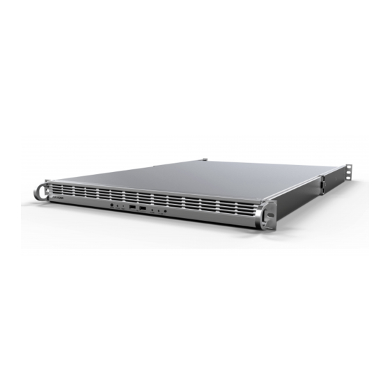
User Manual of iDS-TP40-16B Traffic Incident Detection Server Chapter 2 Hardware Introduction 2.1 Specifications Below is a hardware list of traffic incident detection server, here iDS-TP40-16B is taken as an example. Table 2-1 Technical Specifications Item iDS-TP40-16B Operation Interface Network Interface 4 ×... -
Page 10: Rear Panel Of Ids-Tp40-16B
User Manual of iDS-TP40-16B Traffic Incident Detection Server Table 2-2 Buttons and Indicators on Front Panel No. Item Description Power button: turn on/off the power; press and hold for 3s to force shut down the device. Power Button/Indicator Power indicator: turns blue when the device is powered on. -
Page 11: Available Models
User Manual of iDS-TP40-16B Traffic Incident Detection Server Redundant 1+1 Power Connects to power cable and provides redundant Input Interface power. 2.4 Available Models Product Series Features Remark Access of 16-ch camera for The hardware that is real-time video stream analysis;... - Page 12 User Manual of iDS-TP40-16B Traffic Incident Detection Server Preparation Check the whether the packaging is damaged. Pick a proper installation location that is dust-free and well-ventilated. Avoid heat/noise generating environment; be close to grounded power socket. Keep the device in dry environment. Rain drops, moisture and liquids will corrode the circuit.
- Page 13 User Manual of iDS-TP40-16B Traffic Incident Detection Server 3. Fix the second part of inner rail on the device using 2 M4 flat head screws as shown in Figure 2-3. 4. Repeat the previous step to install the inner rail on the other side.
- Page 14 User Manual of iDS-TP40-16B Traffic Incident Detection Server Figure 2-4 Install Outer Rails Installing Server on Chassis 1. Make sure the inner rails are installed on the server and the outer rails are installed on the chassis. 2. Align the inner and outer rails, as shown in Figure 2-5.
- Page 15 User Manual of iDS-TP40-16B Traffic Incident Detection Server Figure 2-5 Install Server on Chassis 3. Push the server along the outer rails and 2 clicks can be heard. Push the server until it is completely mounted into the chassis. 4. (Optional) Fix the server on the chassis using 2 groups of M5x16 screws and bowl washers, as...
- Page 16 User Manual of iDS-TP40-16B Traffic Incident Detection Server Figure 2-6 Fix the Server When pulling the server out of the chassis, move the plastic paddle up on the left, and move the plastic paddle down on the right.
-
Page 17: Typical Application
User Manual of iDS-TP40-16B Traffic Incident Detection Server 2.5.2 Typical Application Figure 2-7 Typical Application... -
Page 18: Chapter 3 Getting Started
User Manual of iDS-TP40-16B Traffic Incident Detection Server Chapter 3 Getting Started 3.1 Activation You need to active the device and set the password for first-time login. You can activate via SADP or web browser. 3.1.1 Activating via SADP SADP software is enclosed on the compact disc. You can also download it from the company website. - Page 19 User Manual of iDS-TP40-16B Traffic Incident Detection Server Figure 3-2 Create the Password STRONG PASSWORD RECOMMENDED–A strong password ranges from 8 to 16 characters, and must contain at least two of the following categories: numbers, lowercases, uppercases and special characters. And we recommend you reset your password regularly, especially in the high security system, resetting the password monthly or weekly can better protect your product.
-
Page 20: Activating Via Web Browser
User Manual of iDS-TP40-16B Traffic Incident Detection Server Figure 3-3 Modify the Parameters Step 5 Enter the password of the admin account of the device in the Admin Password field and click Modify to modify the parameters. When setting IP address, keep the device IP address and the computer IP address in the same network segment. -
Page 21: Login
User Manual of iDS-TP40-16B Traffic Incident Detection Server Step 2 Enter the user name (admin), activation password, and confirm the password. Step 3 Click Activate to activate the device. STRONG PASSWORD RECOMMENDED–A strong password ranges from 8 to 16 characters, and must contain at least two of the following categories: numbers, lowercases, uppercases and special characters. -
Page 22: Chapter 4 Network Configuration
User Manual of iDS-TP40-16B Traffic Incident Detection Server Chapter 4 Network Configuration Purpose The traffic incident detection server contains eight smart analysis units, used to do smart analysis of cameras. You can view the information of the smart analysis units, and configure the network of the server. -
Page 23: Configuring Network Of Traffic Incident Detection Server
User Manual of iDS-TP40-16B Traffic Incident Detection Server You cannot configure the network parameters of the smart analysis units. 4.2 Configuring Network of Traffic Incident Detection Server Purpose There are four network interfaces of the server. LAN represents G1 and G2 interfaces. They share one IP address for debugging. - Page 24 User Manual of iDS-TP40-16B Traffic Incident Detection Server 2) Configure the network parameters. 3) Click Save and the note pops up as below. Figure 4-5 Note (1) 4) Click OK to save the settings. Step 3 Configure LAN1 or LAN2.
- Page 25 User Manual of iDS-TP40-16B Traffic Incident Detection Server Figure 4-7 Note (2) 4) Click OK to save the settings.
-
Page 26: Chapter 5 System Configuration
User Manual of iDS-TP40-16B Traffic Incident Detection Server Chapter 5 System Configuration 5.1 Basic Configuration Purpose You can configure the IP address and port of the listening server, and the SDK port of the device. Step 1 Go to System Management > System Configuration > Basic Configuration. - Page 27 User Manual of iDS-TP40-16B Traffic Incident Detection Server Figure 5-2 Time Sync. by NTP Server If the device is connected to a public network, you should use a NTP server that has a time synchronization function, such as the server at the National Time Center (IP Address: 210.72.145.44).
-
Page 28: Chapter 6 Resource Management
User Manual of iDS-TP40-16B Traffic Incident Detection Server Chapter 6 Resource Management Purpose You need to add cameras to the server and manage them in resource management. The cameras should be added according to the group structure. There are four levels of the structure. The first level is administrator and you can add control centers or areas to it. - Page 29 User Manual of iDS-TP40-16B Traffic Incident Detection Server Figure 6-3 Select Group Step 6 Select the group to add the control center or area. You cannot add a control center to an area or add an area to an area. Or the note pops up to remind you to check if the selected one is local control center.
-
Page 30: Adding Device
User Manual of iDS-TP40-16B Traffic Incident Detection Server Figure 6-5 Add Group Step 8 Click Save to save the settings. 6.3 Adding Device Purpose You can add device to administrator or a control center. Step 1 Go to Resource Management. -
Page 31: Adding Camera
User Manual of iDS-TP40-16B Traffic Incident Detection Server Figure 6-7 Add Device Step 4 Configure the parameters. Protocol Type: ONVIF and SDK are selectable. Control Center: Select a control center to add the device. Device Name: Enter the name of the device. - Page 32 User Manual of iDS-TP40-16B Traffic Incident Detection Server Figure 6-8 Resource Management Step 2 Click Add. Step 3 Select Add Camera. Figure 6-9 Add Camera Step 4 Click Area to select the area to add the camera. You must select the area belonging to the control center which has been added devices or...
- Page 33 User Manual of iDS-TP40-16B Traffic Incident Detection Server Figure 6-10 Select Area Step 5 Click Camera to add the camera which has been added in the upper-level control center. 1) Check the camera(s) to be added. 2) Click OK to add the camera(s).
-
Page 34: Modifying The Added Device/Camera
User Manual of iDS-TP40-16B Traffic Incident Detection Server 6.5 Modifying the Added Device/Camera Purpose After adding devices/cameras, you can modify the information of them. Step 1 Go to Resource Management. The added devices/cameras will be listed on the right. Figure 6-12 Device/Camera List Step 2 Check the added device/camera and click Modify or click a device name to enter the modification page. -
Page 35: Deleting The Added Device/Camera
User Manual of iDS-TP40-16B Traffic Incident Detection Server Step 2 Select a control center or area from the left tree. Step 3 Click Modify. Figure 6-14 Modify Group Step 4 Modify the Name. Step 5 Click Save to save the settings. -
Page 36: Exporting Control Center/Area/Device Information
User Manual of iDS-TP40-16B Traffic Incident Detection Server Figure 6-16 Delete Group Step 4 Click OK to delete the group. 6.9 Exporting Control Center/Area/Device Information Purpose You can export the added control center/area/device information to the local PC. Step 1 Go to Resource Management. -
Page 37: Importing Control Center/Area/Device Information
User Manual of iDS-TP40-16B Traffic Incident Detection Server Figure 6-19 Area Information Figure 6-20 Device Information The parent ID of the control center refers to the ID of the local root directory. The parent ID of area shall be the same with the ID of the control center containing the area. - Page 38 User Manual of iDS-TP40-16B Traffic Incident Detection Server Figure 6-22 Export Template Step 4 Click OK to export and save the template to the local PC. Step 5 Edit the template. You can refer to step 4 of Chapter 6.9 Exporting Control Center/Area/Device Information for reference.
-
Page 39: Chapter 7 Live View
User Manual of iDS-TP40-16B Traffic Incident Detection Server Chapter 7 Live View Purpose After adding the devices/cameras, you can view the real-time video in the live view page. Step 1 Go to Live View. The added devices/cameras are listed on the left Camera List. - Page 40 User Manual of iDS-TP40-16B Traffic Incident Detection Server Only speed dome supports manual evidence capture. The traffic incident detection server shall be armed on DS-TP50-12DT terminal server or iVMS-8600 platform first. The captured pictures will be stored in the directory configured...
-
Page 41: Chapter 8 Camera Configuration
User Manual of iDS-TP40-16B Traffic Incident Detection Server Chapter 8 Camera Configuration 8.1 Configuring Camera Location Purpose You can configure the location of the camera. Step 1 Go to Camera Configuration > Camera Location. Figure 8-1 Camera Location Configuration Step 2 Configure the parameters. -
Page 42: Configuring Character Overlay
User Manual of iDS-TP40-16B Traffic Incident Detection Server For the captured pictures of the detected incidents, you can configure the picture composition mode. Step 1 Go to Camera Configuration > Picture Composition. Figure 8-2 Picture Composition Configuration Step 2 Configure the parameters. - Page 43 User Manual of iDS-TP40-16B Traffic Incident Detection Server Figure 8-3 Character Overlay Configuration Step 2 Configure the parameters. Select Channel: Select the camera for character overlay configuration. Overlay Mode: Select the overlay mode. You can overlay characters below picture, above picture, or inside picture.
-
Page 44: Configuring Scene
User Manual of iDS-TP40-16B Traffic Incident Detection Server Foreground/Background Color RGB: Click to select the foreground/background color. Overlay Content: 1) Click the text field to enter the Overlay Information Configuration page. Figure 8-4 Overlay Information Configuration 2) Check the content to be overlaid on the pictures. - Page 45 User Manual of iDS-TP40-16B Traffic Incident Detection Server Configure the number of lane(s), lane property, and draw the lanes. Step 1 Go to Camera Configuration > Scene. Step 2 Select the channel for lane configuration. Step 3 Select the scene.
-
Page 46: Configuring Incident Rule
User Manual of iDS-TP40-16B Traffic Incident Detection Server Figure 8-6 Lane Information Configuration 1) Select the Lane Type. Normal Lane and Non-Motor Vehicle Lane are selectable. 2) Select the Lane Direction. Undefined, Front, and Back are selectable. 3) Select the Left Lane Line Type. Solid White Line, Dotted Line, and Yellow Line are selectable. - Page 47 User Manual of iDS-TP40-16B Traffic Incident Detection Server Figure 8-7 Incident Rule Configuration Step 5 Select the Scene Mode. Unknown Scene Mode, High-Speed Scene Mode, Urban Scene Mode, and Tunnel/Underground Parking Lot Mode are selectable. Step 6 Check the incident type(s) for detection.
- Page 48 User Manual of iDS-TP40-16B Traffic Incident Detection Server Figure 8-9 Wrong-Way Driving The lane direction shall be configured in lane information configuration first. Refer to Chapter 8.4.1 Configuring Lane for reference. Pedestrian: Configure the following parameters. When it detects that a pedestrian is passing through the lane for the configured duration, the alarm will be triggered.
- Page 49 User Manual of iDS-TP40-16B Traffic Incident Detection Server Figure 8-12 Illegal Lane Change You shall configure the lane line as dotted line, solid white line, or yellow line first. Refer to Chapter 8.4.1 Configuring Lane for reference. Objects Dropped Down: Configure the following parameters. When it detects that there are dropped objects on the lane for the configured duration, the alarm will be triggered.
- Page 50 User Manual of iDS-TP40-16B Traffic Incident Detection Server Figure 8-15 Congestion Flow: Configure the following parameters. The traffic flow will be counted every count time, and the information will be uploaded via SDK. Figure 8-16 Flow Roadblock: Configure the following parameters. When it detects that roadblock appears on the lane for the configured duration, the alarm will be triggered.
-
Page 51: Configuring Preset Scene
User Manual of iDS-TP40-16B Traffic Incident Detection Server 8.4.3 Configuring Preset Scene Purpose You can configure the PTZ of the camera, the preset scene and the illegal parking capture parameters in the scene. Step 1 Go to Camera Configuration > Scene. - Page 52 User Manual of iDS-TP40-16B Traffic Incident Detection Server Figure 8-20 Scene Location Configuration Step 6 Configure the basic parameters. 1) Check Enable This Scene to enable the scene. 2) Enter the Scene Name. 3) Select the Direction. Step 7 Configure the illegal parking capture parameters.
-
Page 53: Configuring Manual Evidence Capture
User Manual of iDS-TP40-16B Traffic Incident Detection Server 8.5 Configuring Manual Evidence Capture Purpose Except smart capture of different types of illegal parking, you can also capture the incidents manually. Configure the manual evidence capture parameters before capturing manually. Step 1 Go to Camera Configuration > Manual Evidence Capture. -
Page 54: Configure Scene Patrol
User Manual of iDS-TP40-16B Traffic Incident Detection Server Step 7 Click Save to save the settings. 8.6 Configure Scene Patrol Purpose You can configure the scene patrol schedule of each day in a week. Then the configured scene will be enabled according to the scene schedule. - Page 55 User Manual of iDS-TP40-16B Traffic Incident Detection Server e) (Optional) Click to delete the rule. Click Save to save the settings. Figure 8-25 Auto-Switch Scene Configuration Step 5 Repeat step 4 to configure the other periods. Step 6 Repeat the steps above to configure the other days in a week.
-
Page 56: Chapter 9 Management And Maintenance
User Manual of iDS-TP40-16B Traffic Incident Detection Server Chapter 9 Management and Maintenance 9.1 Viewing Performance of the Server Purpose You can view the CPU usage rate, network IO, and temperature of the server. Step 1 Go to Network Management > Local > Performance. -
Page 57: Searching Log Files
User Manual of iDS-TP40-16B Traffic Incident Detection Server Figure 9-2 Performance in Bar Chart Mode 9.2 Searching Log Files Purpose The operation and alarm information of the server can be stored in log files, which can be viewed and exported at any time. -
Page 58: Upgrading Software
User Manual of iDS-TP40-16B Traffic Incident Detection Server Figure 9-4 Note 2) Click OK to export the log files. 3) Select the directory to save the log files. Then the log files will be saved in the local PC in the format of txt. - Page 59 User Manual of iDS-TP40-16B Traffic Incident Detection Server Figure 9-7 Upload File Step 5 After the file is uploaded, click Next to confirm the operation. Figure 9-8 Confirm the Operation Step 6 Click OK to start upgrading. Figure 9-9 Start Upgrading Step 7 After the file is completely uploaded, click Exit to finish upgrade.
-
Page 60: Restoring Default Settings
User Manual of iDS-TP40-16B Traffic Incident Detection Server 9.4 Restoring Default Settings Purpose You can simply restore the server or restore all the parameters of the server to default settings. Step 1 Go to System Management > System Configuration > Default Configuration. -
Page 61: Managing User Accounts
User Manual of iDS-TP40-16B Traffic Incident Detection Server Figure 9-13 Restore All Step 4 Click OK to restore. The device will reboot automatically after restoring to the default settings. 9.5 Managing User Accounts Purpose There is a default account in the DVR: Administrator. You can configure a new password for the admin. - Page 62 User Manual of iDS-TP40-16B Traffic Incident Detection Server Step 4 Click Save to save the settings. 0100001071010...
- Page 63 User Manual of iDS-TP40-16B Traffic Incident Detection Server...
Need help?
Do you have a question about the iDS-TP40-16B and is the answer not in the manual?
Questions and answers