Advertisement
Installation and Service Instructions for Carestation 650c Pendant anesthesia machine
Read through these entire instructions before beginning the installation.
WARNING
This pendant mount anesthesia machine must be installed by GE Healthcare
Authorized service personnel having experience with anesthesia machine
equipment.
WARNING
This device, when removed from its ceiling mount, does not meet the
stability requirements of IEC 80601-2-13 and IEC 60601-1 respectively. Special
caution has to be taken.
Carestation 650c Pendant anesthesia machines (factory-configured) are designed for attachment to Draeger or
TRUMPF (Kreuzer) or Maquet pendant lift interfaces.
These instructions are for mounting a Carestation 650c Pendant anesthesia machine onto a pendant lift.
WARNING Mass limit of the pendant anesthesia system is 180 kg (396 Ibs).
Tools needed
•
Standard hand tools
•
Measuring tape
•
Carestation 600 Series Technical Reference Manual
( PN: 2076163-001)
Installation procedure
1.
Verify that the maximum loading allowance of the pendant lift is
sufficient to carry total weight of Carestation 650c anesthesia machine.
Note: Carestation 650c weight and center of gravity location are shown in
WARNING
Do not overload the pendant lift. Make sure the
maximum loading allowance of the pendant lift
is verified and the result is recorded.
2.
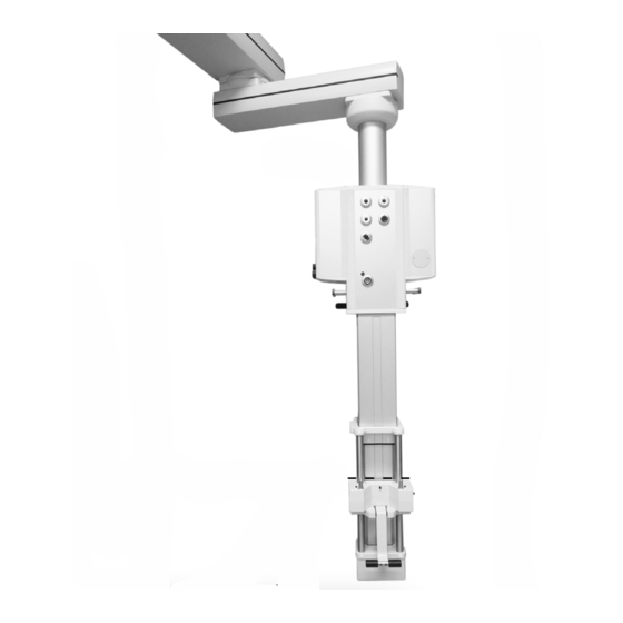
Lower the pendant lift to the bottom position. Make sure that the
minimum distance from the top of the lift pins to the ground (A) is less than 550 mm (21.65 inches).
Note: If the pendant lift cannot be lowered to above required height, contact the pendant lift supplier to replace the
beam (B).
WARNING
Do not proceed with the installation if the pendant lift does not meet above
requirement.
Datex-Ohmeda, Inc.
3030 Ohmeda Drive
PO Box 7550
Madison, WI 53707-7550, USA
This document contains confidential information or proprietary information of General Electric Company or its af-
filiates. Neither the document nor the information therein is to be reproduced, distributed, used, or disclosed, either
in whole or in part, except as specifically authorized in writing by a General Electric Company and must be returned
upon request.
Installation Instructions,
For future reference add to your Technical Reference Manual
B
Top of lift pins
A
Ground
M1807013 Rev. F
For Field Use
01 15
Page 1 of 6
Advertisement
Table of Contents

Related Manuals for GE Carestation 650c


Summary of Contents for GE Carestation 650c
-
Page 1: Tools Needed
Carestation 650c Pendant anesthesia machines (factory-configured) are designed for attachment to Draeger or TRUMPF (Kreuzer) or Maquet pendant lift interfaces. These instructions are for mounting a Carestation 650c Pendant anesthesia machine onto a pendant lift. WARNING Mass limit of the pendant anesthesia system is 180 kg (396 Ibs). - Page 2 For future reference add to your Technical Reference Manual Unpack the transportation package from the pendant mount anesthesia machine. If present, remove any extra load attached to the Carestation 650c top shelf and tabletop; for example, monitors, accessories, etc. Loosen the screws of the two tilt blocks (located on the lower rear panel of anesthesia machine). Slide the tilt blocks to the far left and far right positions.
- Page 3 Installation Instructions, For Field Use For future reference add to your Technical Reference Manual Move the machine to the pendant lift. Ensure the lift pins (D) align properly with machine pendant mount holes (E). Turn the tilt adjustment screw clockwise till the hinge supports the anesthesia machine evenly. WARNING This step is essential safety related, make sure it is completed and record the result.
- Page 4 Installation Instructions, For Field Use For future reference add to your Technical Reference Manual lower pendant tilt bracket (the black rod). Tighten the M5 screws of the tilt blocks with torque of 3.39 ± 0.17 Nm. Note: To prevent side tilting, it is important to install the tilt blocks before adding any accessories to the machine. WARNING The screws must be tightened to required torque.
- Page 5 Installation Instructions, For Field Use For future reference add to your Technical Reference Manual the adjacent area are still aligned. Tighten the screws if loose. NOTE: The rear upper panel and the rear lower panel need to be removed for checking the screws fixing the machine with the mounting bracket.
- Page 6 Installation Instructions, For Field Use For future reference add to your Technical Reference Manual APPENDIX 1 Datex-Ohmeda, Inc. This document contains confidential information or proprietary information of General Electric Company or its af- 3030 Ohmeda Drive filiates. Neither the document nor the information therein is to be reproduced, distributed, used, or disclosed, either in whole or in part, except as specifically authorized in writing by a General Electric Company and must be returned PO Box 7550 Madison, WI 53707-7550, USA...
Need help?
Do you have a question about the Carestation 650c and is the answer not in the manual?
Questions and answers