Table of Contents
Advertisement
Quick Links
INSTALLATION CERTIFICATE
The undersigned qualified installer attests having personally fitted the here described vehicle
security system following the manufacturer instructions.
By :
931R12
Sold on :
T
ype of product
:
931R12
................................................
Vehicle :
..........................................................................................................................
INSTALLATION AND
USE MANUAL
UK
GEMINI Technologies S.p.A.
Via Luigi Galvani 12 - 21020 Bodio Lomnago (VA) - Italia
Tel. +39 0332 943211 - Fax +39 0332 948080
www.gemini-alarm.com
Rev. 01 - 10/12
ISO 9001 Certified Company
Made in Italy
Advertisement
Table of Contents

Subscribe to Our Youtube Channel
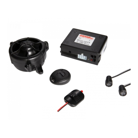
Summary of Contents for Gemini 931R12
- Page 1 ..........Vehicle : .......................... INSTALLATION AND USE MANUAL GEMINI Technologies S.p.A. Via Luigi Galvani 12 - 21020 Bodio Lomnago (VA) - Italia Tel. +39 0332 943211 - Fax +39 0332 948080 www.gemini-alarm.com Rev. 01 - 10/12 ISO 9001 Certified Company...
-
Page 2: Table Of Contents
1.0 - PRELIMINARY ADVICE TABLE OF CONTENTS Dear Customer, the 931R12 is a universal CAN BUS alarm system which can also, with a simple 2 - PRELIMINARY ADVICE..................... PAGE 03 wire hook-up, be used for central door locking (only for vehicles with negative pulse door locks). -
Page 3: Remote Control
USER MANUAL ALARM LED FLASHES ALARM CAUSES CYCLES 3.0 - OPERATING DESCRIPTION Ignition attempt (+15/54) Door opening 3.1 - COMPLETE SYSTEM ARMING Bonnet opening Press the lock button on the vehicle original remote control or press button “1” on the supplied remote control ;... -
Page 4: Emergency Disarming By Pin-Code
If, when disarming with the PIN-CODE, the LED flashes more than 9 times, the The guarantee is valid exclusively at authorized Gemini Technologies S.p.A. Service Centers. procedure will be considered a theft attempt. -
Page 5: Installer Manual
INSTALLER MANUAL 9.0 - COMPLETE WIRING DIAGRAM 8.0 - CONNECTOR TABLES Before carrying out all electrical connections, 8.1 - 20-WAY CONNECTOR disconnect the negative battery terminal. WIRE COLOUR POSITION WIRE FUNCTION Re-connect ONLY after Connection - 1 - ----- ----- completion. -
Page 6: Connections For Turn Indicators Activation
11.0 - CONNECTIONS TO ARM/DISARM THE SYSTEM 10.0 - C ONNECTIONS FOR TURN INDICATORS ACTIVATION The 931R12 system can operate in various modes according to the vehicle on which it is installed and 10.1 - STANDARD CONNECTIONS connections that can be made. -
Page 7: Vehicle Code Programming
10 FLASHES AND A SHORT PAUSE A separate leaflet, included in the alarm packaging, lists all the available vehicles (codes are updated at packaging time). Up-to-date information on supported vehicle models can be found at: www.gemini- alarm.com (privat e area). 3 FLASHES The system has a LED indicator that signals any wrong vehicle code inserted. -
Page 8: System Programming
Enabling of coded output for self-powered siren Disabled Door input - positive Disabled Optical pulse signal Enabled For Gemini only, turn ignition key ----- A lack of power during electrical system maintenance, will not affect the programming. PRESS RELEASE Every turn of the ignition key... -
Page 9: Adding New Devices
16.0 - ADDING NEW DEVICES 17.0 - DELETING STORED DEVICES To carry out the operation successfully, make sure the required electrical connections To carry out the operation successfully, make sure the required electrical connections (bonnet switch and ignition) are complete. (bonnet switch and ignition) are complete. -
Page 10: Ultrasonic Volumetric Protection
18.0 - ULTRASONIC VOLUMETRIC PROTECTION 20.0 - TECHNICAL SPECIFICATIONS 18.1 - CO NNECTION AND POSITIONING Power supply 12 Vdc nsert the WHITE connector in the “W” marked socket. Current absorption @ 12Vdc with system armed and LED flashing 15 mA nsert the RED connector in the “R”...


Need help?
Do you have a question about the 931R12 and is the answer not in the manual?
Questions and answers