Table of Contents
Advertisement
Quick Links
Installation instructions
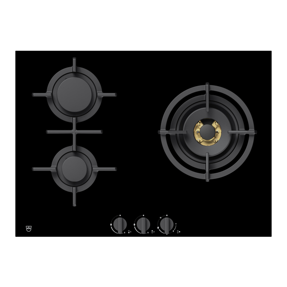
Built-in variants of gas hob
Dials
The appliance must be installed by qualified personnel only. Each step must be carried out and checked in full in the
order specified.
Check that the local connection conditions (gas type and gas pressure) and the appliance setting match before con-
necting the appliance.
The default values for this appliance are provided on the information plate (or on the identification plate).
This appliance is not connected to a combustion by-product outlet. It must be set up and connected according to the
applicable installation conditions. Particular attention must be paid to the relevant ventilation requirements.
If installing into a combustible material, the guidelines and standards for low-voltage installations and fire protection
must be strictly observed.
All leak tests should be done with a soapy water solution. Never use an open flame to check for leaks!
All leak tests should be done with a soapy water solution. Never use an open flame to check for leaks!
Validity
These installation instructions apply to the following models:
Model number
31089
31075
General notes
Identification plate
The identification plate and stickers with the permissible
gas types and safety precautions are located on the under-
side of the hob.
▸
Affix the second identification plate (supplied) in an accessible position behind the front of the fitted cabinet beneath the appliance.
Care and maintenance
▸
Follow the care and cleaning advice in the operating instructions.
▸
Follow the basic maintenance advice in the operating instructions.
Type
GAS641GKAZ
GAS731GKBZ
1
1014402-R05
Appliance class
Class 3
DIN EN 30-1-1
Identification plate
Depending on
appliance, plate
with additional
information
1014402-R05
14/08/2019
Advertisement
Table of Contents

Subscribe to Our Youtube Channel
Related Manuals for V-ZUG 31089


Summary of Contents for V-ZUG 31089
- Page 1 All leak tests should be done with a soapy water solution. Never use an open flame to check for leaks! Validity These installation instructions apply to the following models: Model number Type Appliance class 31089 GAS641GKAZ Class 3 DIN EN 30-1-1 31075 GAS731GKBZ...
- Page 2 1014402-R05 Installation instructions 14/08/2019 Built-in variants of gas hob Dials 1014402-R05 Installation accessories provided For all installation variants: Designation Art. no. 4 adjusting braces H61561 Sealing ring gas connection 18 × 13 × 1.5 mm H64006 Flush installation: Designation Art. no. Cementing-in instructions J004133 Sealing strip set...
- Page 3 Installation instructions 14/08/2019 Built-in variants of gas hob Dials 1014402-R05 Surface-mounted installation The layout of the hob to be fitted may differ from the hob illustrated! GAS641GSAZ (31089) GAS731GKBZ (31075) Y – Y T ≥90 Drawer/ cabinet Side panel * The required clearance must be observed!
- Page 4 14/08/2019 Built-in variants of gas hob Dials 1014402-R05 Flush installation The layout of the hob to be fitted may differ from the hob illustrated! GAS641GSAZ (31089) GAS731GKBZ (31075) Detail Z R0–5 Steel angle bonded or screw mounted Y – Y T ≥90...
- Page 5 1014402-R05 Installation instructions 14/08/2019 Built-in variants of gas hob Dials 1014402-R05 Combination installation Flush-mounted combination installation is described in document 1014381. The intermediate support kit H63789 is required for this. Electrical connection Electrical connections must be carried out by qualified personnel in accordance with the guidelines and standards for low-voltage installations and the specifications of the local electricity supply companies.
- Page 6 1014402-R05 Installation instructions 14/08/2019 Built-in variants of gas hob Dials 1014402-R05 Minimum distances and installation conditions The distance from the appliance cut-out to the back wall must be ≥50 mm and to the side walls ≥200 mm. Parts such as side walls and reinforcing strips which protrude into the installation space under the cooking zone must be made of fire-resistant material.
- Page 7 1014402-R05 Installation instructions 14/08/2019 Built-in variants of gas hob Dials 1014402-R05 Thread length Thread length of gas connection on the appliance (external thread) So is 16 mm. If the thread length of the on-site counterpart (internal thread) Si is longer than 17 mm, the front-end seal is no longer guaranteed through the supplied green sealing ring H64006 with a height of 1.5 mm.
- Page 8 1014402-R05 Installation instructions 14/08/2019 Built-in variants of gas hob Dials 1014402-R05 Flush mounted Surface mounted Place the appliance tray in the kitchen cabinet and up Lift the base plate back onto the base. and over the threaded rods. First tighten the two knurled nuts in the corners. Screw in the screws along the circumference of the ap- pliance.
Need help?
Do you have a question about the 31089 and is the answer not in the manual?
Questions and answers